EP1226073B1 - System zur bearbeitung von partikelförmigen produkten - Google Patents
System zur bearbeitung von partikelförmigen produkten Download PDFInfo
- Publication number
- EP1226073B1 EP1226073B1 EP00965118A EP00965118A EP1226073B1 EP 1226073 B1 EP1226073 B1 EP 1226073B1 EP 00965118 A EP00965118 A EP 00965118A EP 00965118 A EP00965118 A EP 00965118A EP 1226073 B1 EP1226073 B1 EP 1226073B1
- Authority
- EP
- European Patent Office
- Prior art keywords
- container
- following
- particulate product
- product
- Prior art date
- Legal status (The legal status is an assumption and is not a legal conclusion. Google has not performed a legal analysis and makes no representation as to the accuracy of the status listed.)
- Expired - Lifetime
Links
Images


Classifications
-
- B—PERFORMING OPERATIONS; TRANSPORTING
- B65—CONVEYING; PACKING; STORING; HANDLING THIN OR FILAMENTARY MATERIAL
- B65B—MACHINES, APPARATUS OR DEVICES FOR, OR METHODS OF, PACKAGING ARTICLES OR MATERIALS; UNPACKING
- B65B39/00—Nozzles, funnels or guides for introducing articles or materials into containers or wrappers
- B65B39/14—Nozzles, funnels or guides for introducing articles or materials into containers or wrappers movable with a moving container or wrapper during filling or depositing
Definitions
- This invention relates to particulate product filling machines for packaging food products and the like. More particularly, the present invention relates to an improved following system for a particulate product filler which allows higher production line speeds while maintaining volumetric accuracy.
- Particulate food products typically involve a variety of individual pieces mixed together, sometimes with a liquid or sauce.
- Examples of particulate food products include cooked rice, diced vegetables, stir fry vegetables, fruit pieces or fruit cocktail, and various pasta dishes.
- these products may be packaged in a wide variety of containers such as cups, trays, bottles, pouches, etc., which are formed of paper, plastic, or foil.
- the packaging of particulate food products requires special care to prevent large pieces - e.g., the noodles, fruit, or vegetables, etc. -from being chopped or mashed during packaging. For this reason, many of these types of food products are still portioned and packaged by hand.
- particulate product filling machines which employ a bucket follower system, or what is known as a walking beam or walking head system. These machines are often used for adding sauces to certain food products, and typically involve an assembly of buckets or other discharge apparatus which follow a container for some period of time as it moves along the conveyor. By briefly following the moving container, the window of time for discharge is increased relative to the conveyor speed, thus allowing a higher line speed.
- bucket following systems do not solve all of the problems associated with particulate products, and introduce some additional problems as well.
- bucket follower systems may involve anywhere from 2 to 20 or more buckets, all of which must be routinely cleaned, and which must each be removed and replaced whenever a product or container is changed, because each different container size and shape requires a different bucket. This makes the changeover from one product to another very time consuming.
- Raque et al. discloses a following means that guides the dispensed product into a moving container, in accordance with the preamble of claim 1.
- a following pocket is disposed below the discharge opening of the particulate product measuring and dispensing machine and above a conveyor for moving containers to be filled.
- the following pocket comprises a generally vertical aperture which is configured such that particulate product discharged from the discharge opening drops through the aperture before dropping into the container to be filled.
- the aperture may be configured in various shapes to accommodate containers of various shapes.
- the follower pocket is configured to slidably reciprocate in a direction generally parallel to the direction of motion of the container by means of a pneumatic actuator which is preferably controlled by a microprocessor controller which also controls the product measuring and dispensing machine.
- the controller causes the following pocket to move in the direction of motion of the container while particulate product is being discharged from the discharge opening and passing through the aperture, such that the particulate product is caused to move in the direction of the moving container while dropping from the discharge opening.
- a particulate product measuring and dispensing machine wherein the pneumatic drive system is variably actuable, such that its speed, direction of motion, and stroke length may be precisely controlled by the microprocessor controller:
- the microprocessor controller may be selectively adjusted to control the speed and timing of reciprocation of the following pocket and the actuation means synchronously with the operation of the particulate product measuring and dispensing machine so as to place the particulate product precisely into a desired location within the container.
- Sensors may also be provided for detecting the position of a container to be filled relative to the particulate product filling machine and the following pocket, the microcomputer receiving a signal from the sensors representing the position of the container to allow adjustment of the motion of the actuating means relative to the moving container and the particulate product filling machine so as to allow precise placement of the particulate product in the desired location within said container.
- the present invention is best suited for use in conjunction with a particulate product filling system, such as shown in FIG. 1 , comprising a particulate product measuring and filling machine 10, a supply conveyor 12, and container conveyor 14.
- a particulate product measuring and filling machine 10 a particulate product measuring and filling machine 10
- a supply conveyor 12 a particulate product measuring and filling machine 10
- container conveyor 14 container conveyor 14
- the filling machine is shown in longitudinal cross-section, the cross-section taken perpendicular to the direction of travel of the container conveyor 14, which moves into or out of the plane of the drawing.
- the supply conveyor 12 is mounted on a moveable frame 16, to which the measuring and filling machine is also connected. This configuration allows multiple filling machines 10 to be conveniently located and relocated relative to the container conveyor so as to accommodate operations such as multiple product dispensing into multiple compartment containers and so forth, as is well known in the industry.
- the path of the particulate product during operation of the particulate product filling machine 10 is indicated by arrows 18.
- the conveyor 12 draws product out of a supply hopper 20, and drops it into filler tube 22, which directs the product into the inlet 24 of the measuring and filling machine 10.
- the filling machine mechanically measures a discrete quantity of the product, then allows the product to drop through a discharge opening or discharge pocket 30 and into a container 32 located directly below on the container conveyor 14.
- the operation of the various components of this product measuring and filling machine may be controlled by direct mechanical interconnection of the components so as to ensure synchronous operation like clockwork.
- the components may be controlled by a combination of servo systems, detectors, and actuators, which allow synchronous operation.
- the operation of the various components may be controlled by a microprocessor 80, to be described in more detail below.
- the particulate product measuring and filling machine 10 may take a variety of configurations other than that shown. Moreover, the particulate product following system of the present invention does not require a mechanical product measuring and filling apparatus at all, but may instead be supplied with particulate product by means of manual labor wherein workers place a measured portion of product directly into an outlet conduit.
- the present invention further comprises a follower pocket assembly 11 disposed below the discharge pocket 30, which directs the product to the container and allows faster filling of containers while still providing a clean discharge and accurate fill position in the container.
- a follower pocket assembly 11 disposed below the discharge pocket 30, which directs the product to the container and allows faster filling of containers while still providing a clean discharge and accurate fill position in the container.
- the details of operation of this follower pocket are described in detail with reference to figures 2A-2C which present transverse cross-sectional views of the particulate product following system taken along section line 2-2 through the centerline of the discharge pocket 30 as depicted in FIG. 1 .
- the follower pocket assembly 11 comprises a reciprocating follower pocket 44 which is configured to move in the direction of the container conveyor 14, shown by arrow 15, during the discharge phase of the particulate product filling machine 10.
- Fig. 2A depicts the follower pocket 44 retracted in preparation to receive the product from the discharge pocket 30 at the beginning of the discharge phase.
- FIG. 3 provides a pictorial, partial sectional view of a follower pocket 44 according to the present invention.
- the follower pocket 44 generally comprises a substantially solid rectangular body having a flange 70 disposed about its upper perimeter, and a discharge opening 65 formed in its center.
- the follower pocket 44 rests on its flanges 70 upon a ledge 68 formed in an opening 67 provided in the follower pocket base 17.
- the opening 67 is longer than the follower pocket 44 as shown by line 78 in FIG. 3 to provide room for it to reciprocate therein.
- reciprocal linear motion of the follower pocket 44 within opening 67 is provided by actuator 60 which moves shaft 62 which extends through an opening in the side of the elongate base 17 and is releasably connected to the follower pocket 44.
- actuator 60 which moves shaft 62 which extends through an opening in the side of the elongate base 17 and is releasably connected to the follower pocket 44.
- This configuration allows quick, easy removal and replacement of the follower pocket 44, such as when changing over the line to prepare to package a new product. Replacement of the follower pocket 44 generally takes less than one minute, whereas changing multiple buckets on a bucket follower machine may take more than an hour, causing significant costly down time.
- the actuator 60 is preferably a pneumatic cylinder, as shown in FIG. 3A .
- other linear actuation devices may be used with this invention which still allow independent control, such as an electric servo motor with a ball and screw mechanism, a solenoid, a hydraulic cylinders, a motor and cam assembly, or other electrical or mechanical devices.
- the follower pocket could also be mechanically connected to the conveyor 14, to ensure synchronous reciprocation.
- a pneumatic actuator is presently preferred because of its fast reaction speed, low operating temperature, and because its motion may be precisely controlled.
- the pneumatic cylinder 60 is connected to a pneumatic actuator 61, which in turn is controlled by the controller 80, to be described in more detail below.
- the timing, stroke length s (the length of reciprocal travel of the follower pocket 44), and speed of motion of the follower pocket are preferably selectively controlled by the controller 80 to synchronize with the other components of the filling system 11. It will be apparent that this timing will depend on the length L of the container to be filled the pitch P between containers on the conveyor, the dimension D of the discharge pocket 30, and the drop height h measured from the top of the follower pocket 44 to the bottom of the container 32. The measurement of all of these physical parameters are shown in FIG. 2A . It will be apparent that the stroke length s of the follower pocket depends on the total length of the opening 67, and the point at which the extension of the pneumatic shaft is caused to stop by the controller 80.
- the discharge pocket 30 may be any shape, such as circular, eliptical, oval, rectangular, etc. in cross-section. It will be apparent that the discharge pocket is preferably the same shape as the filler tube 22, such as having a circular dimension D, representing a diameter as indicated in FIG. 2A .
- the cross-section of the discharge pocket opening is represented by hidden line 30 in FIG. 3 .
- the central opening 65 of the follower pocket 44 preferably comprises at its top an oblong shape 74 which is elongated in the direction of motion of the conveyor 14.
- the lower end 76 of the opening 65 may be any desired shape, such as round as shown in FIG. 3 . It will be appreciated that the ends of the oblong opening 74 should have a radius equal to the radius of the discharge pocket 30. This configuration allows the follower pocket opening 65 to mate with the discharge pocket 30 at all stages of its reciprocation.
- the sides 66 of the central opening 65 will be sloped in some manner.
- the inner sides 66 of opening 65 preferably have fore and aft sides which slope toward the center of the follower pocket, from top to bottom, as shown in the cross-sectional views of FIGs. 2A-2C .
- This configuration functions to direct the falling product 42 contrary to the direction of motion of the conveyor 14 at the beginning of the discharge phase, when the container is generally behind the discharge opening ( FIG. 2A ), and helps push the falling product in the direction of motion of the conveyor 14 at the end of the discharge phase when the container is ahead of the discharge opening ( FIG. 2C).
- FIG. 2B shows the follower pocket 44 partially extended during the discharge phase so as to follow the product container 32 as it moves along the conveyor 14.
- FIG. 2C shows the follower pocket 44 completely extended to the opposite end of the opening 67 at the end of the discharge phase so as to allow the entire product portion to drop into the moving product container 32.
- the follower pocket retracts to the position of FIG. 2A , to await the next discharge.
- the entire reciprocal motion cycle of the follower pocket 44 will take place during the discharge phase of the product filler, which may comprise only a fraction of a second.
- This rapid motion of the follower pocket is preferably controlled and timed by means of the controller 80, which presents several advantages over the prior art.
- the follower pocket can be caused to extend and retract very rapidly or very slowly. Rapid extension can help the product to drop and dislodge more quickly by "throwing" it in the direction of the moving container toward the end of the discharge phase.
- the follower pocket can also be caused to extend only part way, or in short bursts. A partial extension will increase the length of the drop relative to the container, allowing placement of product in a long line, if desired, while short bursts create a vibrational effect which helps evacuate the product from the opening 65.
- the maximum rate at which the containers can be filled is 73 containers per minute (cpm) using the prior art particulate product filler 10 under these operating parameters.
- the same containers can be filled at a rate of 110 cpm with a follower pocket having a 2.54 cm (1") stroke moving at approximately the same or greater speed than the container conveyor. This represents an approximately 50% speed increase. It will be apparent that providing a longer follower pocket stroke could allow even greater speed increases.
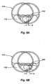
- Figures 4A & B, 5A & B , and 6A & B provide examples of how the speed of product discharge for an arbitrary product can be increased for containers of various shapes where placement of the product in a specific location and in a specific shaped mass is required.
- the shape of the bottom of the follower pocket opening 65 will necessarily depend on the desired shape of the product mass in the container. For example, FIG.
- FIG. 4 shows the placement of a generally triangular mass 100 in the center of the right hand compartment 102 of a rectangular two compartment tray 104.
- a follower pocket stroke of 1.27 cm (0.5")
- a speed of 69 containers per minute is possible.
- FIG. 4B with the same product and the same container, the possible speed increases to 86 cpm with a 2.54 cm (1.0") stroke.
- FIG. 5 shows the placement of an oval or oblong mass 106 at one side of the left hand compartment 108 of the two compartment tray 104.
- the highest possible speed is 87 cpm.
- the stroke length is increased to 2.54 cm (1.0")
- the speed increases to 105 cpm.
- the line speed is 84 cpm
- the available line speed increases to 100 cpm.
- the operation of the components of the particulate product filler 10 and follower pocket assembly 11 as shown in FIG. 1 is preferably controlled by the microprocessor controller 80, which is also connected to the supply conveyor 12, the container conveyor 14, a container sensor 84, and the other components of the particulate product filling system.
- the sensor 84 may be an optical sensor as shown, or may comprise a magnetic sensor, a mechanical sensor which physically touches the container, or any other known type of sensor which can detect the presence of a container.
- the timing of motion can be automatically adjusted based on the speed and position of the container on the conveyor, which may also be adjusted by the controller, and the type and desired placement of the product.
- the system may also include a volume sensing and feedback system, such as a scale 85 for weighing the filled containers while in motion on the conveyor, and transmitting this information to the controller 80 via communication line 86.
- a volume sensing and feedback system such as a scale 85 for weighing the filled containers while in motion on the conveyor, and transmitting this information to the controller 80 via communication line 86.
- This configuration allows the controller to automatically adjust the functioning of the particulate product measuring and filling machine 10 and the follower pocket assembly 11 based on the output volume as measured by the scale.
- the controller 80 is preferably a computer microprocessor which is advantageously programmed with all physical formulas and data necessary for it to calculate the required timing and speed of motion of all components for a variety of products so as to precisely place the product in the container when and where desired. For example, if the container spacing should suddenly increase, the container sensor 84 can detect that, and the controller will automatically delay the timing of the next product drop. Similarly, if it is desired to place the product at the front or back of the container, not in the center, the controller can delay the action of the product measuring and filling machine 10 and the motion of the follower pocket 44 to delay the drop. Such precise timing control and flexibility is not possible with other product filling devices where the parts are mechanically linked to the conveyor line and cannot vary their motion relative to the conveyor.
- controllers may be adapted to control the components of the particulate product filler of this invention.
- an electromechanical controller incorporating electronic indicators, servos, and control switches could be adapted to receive the signals from the various components and allow a user to selectively synchronize the operation of these components for optimal product placement.
- a microcomputer is preferred because of its ease of use and flexibility. If it is desired to change the parameters of operation of the system, such changes can be easily made through a standard computer terminal connected to the controller 80.
- the timing of the various components of the system could be modified "on-the-fly" by adjusting certain values through the computer interface without requiring production to stop even for a few minutes.
- the present invention also adds an additional element which greatly enhances the benefits of this system.
- the pneumatic controller 60 of the follower pocket 44 is controlled by the same controller 80 which controls the motion of all other components.
- This allows the specialized software of the controller to precisely time the motion of the follower pocket, and to quickly adjust to new operating parameters, or vary them as desired. For example, by simply putting new information into the controller terminal, an operator can change the direction of the line, can adjust the discharge volume, and can even instruct the system to adjust to a new product.
- these changes do not require adjustment of the system by trial and error through costly and wasteful repeated brief start-ups and shut-downs, nor does it require the complex and time consuming removal and replacement of multiple mechanical components.
- it provides a particulate product filling system which has significantly higher operating speeds than the prior art.
- the follower pocket system may be used with a line that does not move continuously. In such a system, when the container is stopped under the filling head, the follower pocket can then move from one end to the other to spread the product within the container.
- this system can be configured to move in a direction opposite to the direction of the line to spread the product within the container.
Landscapes
- Engineering & Computer Science (AREA)
- Mechanical Engineering (AREA)
- Basic Packing Technique (AREA)
- Transition And Organic Metals Composition Catalysts For Addition Polymerization (AREA)
- Preparation Of Compounds By Using Micro-Organisms (AREA)
- Electrical Discharge Machining, Electrochemical Machining, And Combined Machining (AREA)
- Constituent Portions Of Griding Lathes, Driving, Sensing And Control (AREA)
Claims (10)
- Ein Behältermitläufersystem zum Einbringen abgemessener Mengen eines partikelförmigen Produkts (52) in einen sich bewegenden Behälter (32), aufweisend:eine mitlaufende Tasche (44), die unterhalb einer Abgabeöffnung (30) für eine Mess- und Abgabemaschine (10) für das partikelförmige Produkt und oberhalb eines sich bewegenden Behälters (32) anordenbar ist, wobei die mitlaufende Tasche dafür ausgelegt ist, dem sich bewegenden Behälter von einer ersten zu einer zweiten Position zu folgen, wobei gleichzeitig das partikelförmige Produkt in den sich bewegenden Behälter abgegeben wird; undein Bewegungsstellglied (60), das mit der mitlaufenden Tasche (44) verbunden ist, um die mitlaufende Tasche in einer geradlinigen hin- und her gehenden Gleitbewegung zu bewegen, welche dem sich bewegenden Behälter (32) folgt;dadurch gekennzeichnet, dass:die mitlaufende Tasche (44) eine vertikale Achse und eine im Wesentlichen vertikale Durchgangsöfffnung (65) hat und so ausgelegt ist, dass das partikelförmige Produkt (52), das von der Abgabeöffnung (30) abgeben wird, im Verlauf des Fallens in den Behälter (32) durch die Öffnung fällt, wobei die mitlaufende Tasche für eine gleitbewegliche Hin- und Herbewegung in einer Richtung im Wesentlichen senkrecht zur vertikalen Achse und im Wesentlichen parallel zur Bewegungsrichtung des Behälters ausgelegt ist;und weiterhin gekennzeichnet durch:eine Steuerung (80) in Verbindung mit der mitlaufenden Tasche (44), dem Bewegungsstellglied (60) und der Mess- und Abgabemaschine (10) für das Produkt, um zu veranlassen, dass die mitlaufende Tasche sich in Bewegungsrichtung des Behälters (32) bewegt, während das partikelförmige Produkt von der Abgabeöffnung (30) abgegeben wird und durch die Öffnung (65) tritt, so dass das partikelförmige Produkt (42) veranlasst wird, sich in Richtung des sich bewegenden Behälters zu bewegen, während es aus der Abgabeöffnung fällt.
- Das Behältermitläufersystem nach Anspruch 1, bei dem das Bewegungsstellglied (60) ein pneumatisches Antriebssystem aufweist.
- Das Behältermitläufersystem nach Anspruch 2, weiterhin dadurch gekennzeichnet, dass das Bewegungsstellglied 60 variabel betätigbar derart ist, dass Geschwindigkeit, Bewegungsrichtung und Hublänge der mitlaufenden Tasche (44) präzise steuerbar sind.
- Das Behältermitläufersystem nach Anspruch 1, weiterhin dadurch gekennzeichnet, dass die Steuerung (80) einen Mikrocomputer aufweist und die Geschwindigkeit und das Zeitverhalten der Hin- und Herbewegung der mitlaufenden Tasche (44) und des Bewegungsstellglieds (60) synchron mit dem Betrieb der Mess- und Abgabemaschine (10) für das partikelförmige Produkt steuert, so dass das partikelförmige Produkt (42) an einem gewünschten Ort innerhalb des Behälters (32) angeordnet wird.
- Das Behältermitläufersystem nach Anspruch 1 oder 2, weiterhin dadurch gekennzeichnet, dass die Steuerung (80) aufweist:einen Sensor (84) zur Erkennung der Position eines zu befüllenden Behälters (32) relativ zu der Füllmaschine (10) für das partikelförmige Produkt und der mitlaufenden Tasche (44);einen Mikrocomputer zu Erhalt eines Signals von dem Sensor (84), das die Position des zu befüllenden Behälters (32) angibt und zum Einstellen der Bewegung des Bewegungsstellglieds (60) relativ zu dem sich bewegenden Behälter und der Füllmaschine (10) für das partikelförmige Produkt basierend auf dem Signal, so dass eine präzise Anordnung des partikelförmigen Produkts (42) an einem gewünschten Ort innerhalb des Behälters möglich ist.
- Das Behältermitläufersystem, weiterhin dadurch gekennzeichnet, dass der Mikrocomputer programmiert ist, um selektiv das pneumatische Antriebssystem (60) zu betätigen, so dass die mitlaufende Tasche (44) in Bewegungsrichtung des Behälters (32) in einer Reihe von raschen kurzen Bewegungsstößen bewegt wird, während der sich bewegende Behälter sich darunter befindet, so dass die mitlaufende Tasche im Ergebnis veranlasst wird, sich langsamer als sonst zu bewegen, und auch um damit eine Vibration in der Struktur der mitlaufenden Tasche hervorzurufen, wodurch das Fallen des partikelförmigen Produkts (42) von der Abgabeöffnung (30) in den Behälter unterstützt wird.
- Das Behältermitläufersystem nach Anspruch 5, weiterhin dadurch gekennzeichnet, dass der Mikrocomputer programmiert ist, das pneumatische Antriebssystem (60) selektiv zu betätigen, um die mitlaufende Tasche (44) in Bewegungsrichtung des Behälters (32) um weniger als einen vollen Hub zu bewegen, wobei die physikalische Länge und Zeitdauer des Hubs der mitlaufenden Tasche geringer als ein voller Hub ist.
- Das Behältermitläufersystem nach Anspruch 1, weiterhin dadurch gekennzeichnet, dass die Öffnung (65) in der mitlaufenden Tasche (44) eine obere Öffnung (74) enthält, die für eine Ausrichtung mit der Abgabeöffnung (30) während der Hin- und Herbewegung der mitlaufenden Tasche ausgelegt ist.
- Das Behältermitläufersystem nach Anspruch 1, weiterhin gekennzeichnet durch:eine Mess- und Abgabemaschine (10) für das partikelförmige Produkt mit einer Abgabeöffnung (30), ausgestaltet zum Messen und voneinander Trennen einzelner Mengen des partikelförmigen Produkts (42) und zum Fallenlassen der einzelnen Mengen durch die Abgabeöffnung und in die mitlaufende Tasche (44);einen Förderer (14) zum Bewegen von Behältern (32) an der Mess- und Abgabemaschine (10) für das partikelförmige Produkt vorbei und unterhalb der Abgabeöffnung (30) und der mitlaufenden Tasche (44); undeine Steuerung (80) zur Steuerung der Funktion der Mess- und Abgabemaschine (10) für das partikelförmige Produkt, den Förderer (14) und die Bewegung des Bewegungsstellglieds (60).
- Das Behältermitläufersystem nach Anspruch 9, weiterhin gekennzeichnet durch Volumenerfassungsmittel (85) zur Erkennung des Volumens des partikelförmigen Produkts (42), das in einen Behälter (32) abzugeben ist, wobei die Volumenerfassungsmittel mit der Steuerung (80) verbunden sind, um eine Rückmeldung zu liefern, die die volumetrische Abgabegenauigkeit der Mess- und Abgabevorrichtung (10) für das partikelförmige Produkt angibt, wodurch das Volumen des Produkts, das von der Messvorrichtung abgetrennt und gemessen wird, von der Steuerung einstellbar ist.
Applications Claiming Priority (3)
| Application Number | Priority Date | Filing Date | Title |
|---|---|---|---|
| US09/397,594 US6145552A (en) | 1999-09-16 | 1999-09-16 | Particulate product following system and method |
| US397594 | 1999-09-16 | ||
| PCT/US2000/025551 WO2001019685A1 (en) | 1999-09-16 | 2000-09-18 | Particulate product following system and method |
Publications (3)
| Publication Number | Publication Date |
|---|---|
| EP1226073A1 EP1226073A1 (de) | 2002-07-31 |
| EP1226073A4 EP1226073A4 (de) | 2005-08-10 |
| EP1226073B1 true EP1226073B1 (de) | 2008-04-23 |
Family
ID=23571840
Family Applications (1)
| Application Number | Title | Priority Date | Filing Date |
|---|---|---|---|
| EP00965118A Expired - Lifetime EP1226073B1 (de) | 1999-09-16 | 2000-09-18 | System zur bearbeitung von partikelförmigen produkten |
Country Status (8)
| Country | Link |
|---|---|
| US (1) | US6145552A (de) |
| EP (1) | EP1226073B1 (de) |
| AT (1) | ATE393097T1 (de) |
| AU (1) | AU7589000A (de) |
| CA (1) | CA2385183C (de) |
| DE (1) | DE60038688T2 (de) |
| ES (1) | ES2304977T3 (de) |
| WO (1) | WO2001019685A1 (de) |
Families Citing this family (7)
| Publication number | Priority date | Publication date | Assignee | Title |
|---|---|---|---|---|
| NL1012438C2 (nl) * | 1999-06-25 | 2001-01-08 | Visser S Gravendeel Holding | Pottenvulmachine. |
| US6269850B1 (en) | 1999-12-03 | 2001-08-07 | Multi-Fill, Inc. | Multipathway product distribution system and method |
| US6619339B2 (en) | 2001-04-04 | 2003-09-16 | Multi-Fill, Inc. | Pneumatically controlled volumetric pocket filler |
| US6595250B1 (en) * | 2002-02-28 | 2003-07-22 | Ideal Manufacturing Sales Corp. | Mobile fluid product filling system with fast setup |
| DE102005031794A1 (de) * | 2005-07-07 | 2007-01-25 | Khs Ag | Verfahren und Vorrichtung zum Überprüfen einer Behälterbehandlungsanlage |
| US7603827B2 (en) * | 2006-12-08 | 2009-10-20 | Boyer Jr Ronald S | Apparatus for packaging of foodstuffs in containers of various dimensions |
| CN106163928A (zh) | 2014-05-21 | 2016-11-23 | 宝洁公司 | 用于分配组合物的方法和系统 |
Family Cites Families (11)
| Publication number | Priority date | Publication date | Assignee | Title |
|---|---|---|---|---|
| US1992464A (en) * | 1933-10-06 | 1935-02-26 | Elgin Mfg Company | Straight line multiple filling machine |
| US2999517A (en) * | 1958-01-17 | 1961-09-12 | Bata Shoe Company Of Canada Lt | Automatic filling device for travelling moulds |
| US3065775A (en) * | 1959-07-28 | 1962-11-27 | Diamond Crystal Salt Co | Liquid dispensing apparatus |
| US3887110A (en) * | 1970-09-10 | 1975-06-03 | Upjohn Co | Dispensing methods and apparatus |
| FR2581025B1 (fr) * | 1985-04-25 | 1987-06-12 | Cetec Ind | Procede et appareil pour remplir des sacs |
| US4678015A (en) * | 1986-04-03 | 1987-07-07 | Raque Food Systems, Inc. | Product apportioning system |
| US4733803A (en) * | 1986-06-23 | 1988-03-29 | Carnation Company | Particulate dispensing apparatus |
| US5297597A (en) * | 1993-01-26 | 1994-03-29 | Herzog Kenneth J | Container filler indexing counter |
| US5641008A (en) * | 1995-02-28 | 1997-06-24 | Ellis; C. Mitchell | Potting machine |
| US5651401A (en) * | 1995-06-14 | 1997-07-29 | Sahara Natural Foods, Inc. | Apparatus for filling receptacles |
| JP2633820B2 (ja) * | 1995-06-16 | 1997-07-23 | ボッシュ包装機株式会社 | 液体の圧力充填方法 |
-
1999
- 1999-09-16 US US09/397,594 patent/US6145552A/en not_active Expired - Lifetime
-
2000
- 2000-09-18 DE DE60038688T patent/DE60038688T2/de not_active Expired - Lifetime
- 2000-09-18 WO PCT/US2000/025551 patent/WO2001019685A1/en not_active Ceased
- 2000-09-18 ES ES00965118T patent/ES2304977T3/es not_active Expired - Lifetime
- 2000-09-18 EP EP00965118A patent/EP1226073B1/de not_active Expired - Lifetime
- 2000-09-18 AU AU75890/00A patent/AU7589000A/en not_active Abandoned
- 2000-09-18 AT AT00965118T patent/ATE393097T1/de not_active IP Right Cessation
- 2000-09-18 CA CA002385183A patent/CA2385183C/en not_active Expired - Fee Related
Also Published As
| Publication number | Publication date |
|---|---|
| EP1226073A1 (de) | 2002-07-31 |
| AU7589000A (en) | 2001-04-17 |
| CA2385183C (en) | 2008-12-30 |
| DE60038688T2 (de) | 2009-07-02 |
| ES2304977T3 (es) | 2008-11-01 |
| CA2385183A1 (en) | 2001-03-22 |
| EP1226073A4 (de) | 2005-08-10 |
| DE60038688D1 (de) | 2008-06-05 |
| WO2001019685A1 (en) | 2001-03-22 |
| US6145552A (en) | 2000-11-14 |
| ATE393097T1 (de) | 2008-05-15 |
Similar Documents
| Publication | Publication Date | Title |
|---|---|---|
| CA2754198C (en) | Variable diameter, variable pitch auger with material scraper and breaker bar | |
| CA2103125C (en) | Filling machine | |
| EP2864209B1 (de) | Bündelungssystem | |
| US11582975B2 (en) | Food processing system and a food processing method | |
| EP1226073B1 (de) | System zur bearbeitung von partikelförmigen produkten | |
| GB2375092A (en) | Rotary gate discharger and reciprocal conveyor combination | |
| US4540082A (en) | Vibratory distribution system | |
| US7220176B2 (en) | System and method for production of exact weight ground meat | |
| EP1268279B1 (de) | System und verfahren für mehrwegverteilung von produkten | |
| US3731715A (en) | Volumetric filling apparatus | |
| US4536146A (en) | Croquette machine | |
| WO2014066496A1 (en) | Bulk feeding system and method | |
| JPS5835658B2 (ja) | 焼平鍋位置制御装置 | |
| EP4106932B1 (de) | Feinkohletrennvorrichtung und -verfahren | |
| US5183507A (en) | Particulate material dispensing device | |
| CA2442894C (en) | Pneumatically controlled volumetric pocket filler | |
| WO2008116002A1 (en) | Bulk feeding system and method | |
| US6964285B1 (en) | Apparatus for filling food trays at high speeds | |
| EP2661964A1 (de) | Förderschnecke mit variablem Durchmesser und variabler Steigung mit Materialabstreifer und Brechstange | |
| US3347177A (en) | Machines for preparing food products from dough | |
| US20250248435A1 (en) | Nozzle for a food printer | |
| GB2101950A (en) | Vibratory distribution system | |
| JPH0644400Y2 (ja) | 食品の成形配列装置 | |
| JPS61176822A (ja) | 食料品の計量装置 |
Legal Events
| Date | Code | Title | Description |
|---|---|---|---|
| PUAI | Public reference made under article 153(3) epc to a published international application that has entered the european phase |
Free format text: ORIGINAL CODE: 0009012 |
|
| 17P | Request for examination filed |
Effective date: 20020412 |
|
| AK | Designated contracting states |
Kind code of ref document: A1 Designated state(s): AT BE CH CY DE DK ES FI FR GB GR IE IT LI LU MC NL PT SE |
|
| AX | Request for extension of the european patent |
Free format text: AL;LT;LV;MK;RO;SI |
|
| A4 | Supplementary search report drawn up and despatched |
Effective date: 20050623 |
|
| RIC1 | Information provided on ipc code assigned before grant |
Ipc: 7B 65B 39/14 B Ipc: 7B 65B 43/42 A |
|
| RTI1 | Title (correction) |
Free format text: PARTICULATE PRODUCT FOLLOWING SYSTEM |
|
| GRAP | Despatch of communication of intention to grant a patent |
Free format text: ORIGINAL CODE: EPIDOSNIGR1 |
|
| GRAS | Grant fee paid |
Free format text: ORIGINAL CODE: EPIDOSNIGR3 |
|
| GRAA | (expected) grant |
Free format text: ORIGINAL CODE: 0009210 |
|
| AK | Designated contracting states |
Kind code of ref document: B1 Designated state(s): AT BE CH CY DE DK ES FI FR GB GR IE IT LI LU MC NL PT SE |
|
| REG | Reference to a national code |
Ref country code: GB Ref legal event code: FG4D |
|
| REG | Reference to a national code |
Ref country code: CH Ref legal event code: EP |
|
| REF | Corresponds to: |
Ref document number: 60038688 Country of ref document: DE Date of ref document: 20080605 Kind code of ref document: P |
|
| REG | Reference to a national code |
Ref country code: IE Ref legal event code: FG4D Free format text: LANGUAGE OF EP DOCUMENT: FRENCH |
|
| PG25 | Lapsed in a contracting state [announced via postgrant information from national office to epo] |
Ref country code: PT Free format text: LAPSE BECAUSE OF FAILURE TO SUBMIT A TRANSLATION OF THE DESCRIPTION OR TO PAY THE FEE WITHIN THE PRESCRIBED TIME-LIMIT Effective date: 20080923 Ref country code: FI Free format text: LAPSE BECAUSE OF FAILURE TO SUBMIT A TRANSLATION OF THE DESCRIPTION OR TO PAY THE FEE WITHIN THE PRESCRIBED TIME-LIMIT Effective date: 20080423 |
|
| REG | Reference to a national code |
Ref country code: ES Ref legal event code: FG2A Ref document number: 2304977 Country of ref document: ES Kind code of ref document: T3 |
|
| PG25 | Lapsed in a contracting state [announced via postgrant information from national office to epo] |
Ref country code: AT Free format text: LAPSE BECAUSE OF FAILURE TO SUBMIT A TRANSLATION OF THE DESCRIPTION OR TO PAY THE FEE WITHIN THE PRESCRIBED TIME-LIMIT Effective date: 20080423 |
|
| ET | Fr: translation filed | ||
| PG25 | Lapsed in a contracting state [announced via postgrant information from national office to epo] |
Ref country code: SE Free format text: LAPSE BECAUSE OF FAILURE TO SUBMIT A TRANSLATION OF THE DESCRIPTION OR TO PAY THE FEE WITHIN THE PRESCRIBED TIME-LIMIT Effective date: 20080723 Ref country code: DK Free format text: LAPSE BECAUSE OF FAILURE TO SUBMIT A TRANSLATION OF THE DESCRIPTION OR TO PAY THE FEE WITHIN THE PRESCRIBED TIME-LIMIT Effective date: 20080423 |
|
| PG25 | Lapsed in a contracting state [announced via postgrant information from national office to epo] |
Ref country code: BE Free format text: LAPSE BECAUSE OF FAILURE TO SUBMIT A TRANSLATION OF THE DESCRIPTION OR TO PAY THE FEE WITHIN THE PRESCRIBED TIME-LIMIT Effective date: 20080423 |
|
| PLBE | No opposition filed within time limit |
Free format text: ORIGINAL CODE: 0009261 |
|
| STAA | Information on the status of an ep patent application or granted ep patent |
Free format text: STATUS: NO OPPOSITION FILED WITHIN TIME LIMIT |
|
| 26N | No opposition filed |
Effective date: 20090126 |
|
| PG25 | Lapsed in a contracting state [announced via postgrant information from national office to epo] |
Ref country code: MC Free format text: LAPSE BECAUSE OF NON-PAYMENT OF DUE FEES Effective date: 20080930 |
|
| REG | Reference to a national code |
Ref country code: CH Ref legal event code: PL |
|
| REG | Reference to a national code |
Ref country code: IE Ref legal event code: MM4A |
|
| PG25 | Lapsed in a contracting state [announced via postgrant information from national office to epo] |
Ref country code: IE Free format text: LAPSE BECAUSE OF NON-PAYMENT OF DUE FEES Effective date: 20080918 |
|
| PG25 | Lapsed in a contracting state [announced via postgrant information from national office to epo] |
Ref country code: LI Free format text: LAPSE BECAUSE OF NON-PAYMENT OF DUE FEES Effective date: 20080930 Ref country code: CH Free format text: LAPSE BECAUSE OF NON-PAYMENT OF DUE FEES Effective date: 20080930 |
|
| PG25 | Lapsed in a contracting state [announced via postgrant information from national office to epo] |
Ref country code: LU Free format text: LAPSE BECAUSE OF NON-PAYMENT OF DUE FEES Effective date: 20080918 Ref country code: CY Free format text: LAPSE BECAUSE OF FAILURE TO SUBMIT A TRANSLATION OF THE DESCRIPTION OR TO PAY THE FEE WITHIN THE PRESCRIBED TIME-LIMIT Effective date: 20080423 |
|
| PG25 | Lapsed in a contracting state [announced via postgrant information from national office to epo] |
Ref country code: GR Free format text: LAPSE BECAUSE OF FAILURE TO SUBMIT A TRANSLATION OF THE DESCRIPTION OR TO PAY THE FEE WITHIN THE PRESCRIBED TIME-LIMIT Effective date: 20080724 |
|
| PGFP | Annual fee paid to national office [announced via postgrant information from national office to epo] |
Ref country code: DE Payment date: 20130918 Year of fee payment: 14 Ref country code: ES Payment date: 20130927 Year of fee payment: 14 |
|
| PGFP | Annual fee paid to national office [announced via postgrant information from national office to epo] |
Ref country code: GB Payment date: 20130918 Year of fee payment: 14 Ref country code: FR Payment date: 20130923 Year of fee payment: 14 |
|
| PGFP | Annual fee paid to national office [announced via postgrant information from national office to epo] |
Ref country code: IT Payment date: 20130926 Year of fee payment: 14 |
|
| PGFP | Annual fee paid to national office [announced via postgrant information from national office to epo] |
Ref country code: NL Payment date: 20130926 Year of fee payment: 14 |
|
| REG | Reference to a national code |
Ref country code: DE Ref legal event code: R119 Ref document number: 60038688 Country of ref document: DE |
|
| GBPC | Gb: european patent ceased through non-payment of renewal fee |
Effective date: 20140918 |
|
| REG | Reference to a national code |
Ref country code: FR Ref legal event code: ST Effective date: 20150529 |
|
| PG25 | Lapsed in a contracting state [announced via postgrant information from national office to epo] |
Ref country code: NL Free format text: LAPSE BECAUSE OF NON-PAYMENT OF DUE FEES Effective date: 20150401 |
|
| PG25 | Lapsed in a contracting state [announced via postgrant information from national office to epo] |
Ref country code: GB Free format text: LAPSE BECAUSE OF NON-PAYMENT OF DUE FEES Effective date: 20140918 Ref country code: DE Free format text: LAPSE BECAUSE OF NON-PAYMENT OF DUE FEES Effective date: 20150401 |
|
| PG25 | Lapsed in a contracting state [announced via postgrant information from national office to epo] |
Ref country code: IT Free format text: LAPSE BECAUSE OF NON-PAYMENT OF DUE FEES Effective date: 20140918 Ref country code: FR Free format text: LAPSE BECAUSE OF NON-PAYMENT OF DUE FEES Effective date: 20140930 |
|
| REG | Reference to a national code |
Ref country code: ES Ref legal event code: FD2A Effective date: 20151029 |
|
| PG25 | Lapsed in a contracting state [announced via postgrant information from national office to epo] |
Ref country code: ES Free format text: LAPSE BECAUSE OF NON-PAYMENT OF DUE FEES Effective date: 20140919 |