EP1226087B1 - Dispositif de moussage pour r cipients de boisson - Google Patents
Dispositif de moussage pour r cipients de boisson Download PDFInfo
- Publication number
- EP1226087B1 EP1226087B1 EP01984551A EP01984551A EP1226087B1 EP 1226087 B1 EP1226087 B1 EP 1226087B1 EP 01984551 A EP01984551 A EP 01984551A EP 01984551 A EP01984551 A EP 01984551A EP 1226087 B1 EP1226087 B1 EP 1226087B1
- Authority
- EP
- European Patent Office
- Prior art keywords
- suction
- container
- containers
- foaming
- edge
- Prior art date
- Legal status (The legal status is an assumption and is not a legal conclusion. Google has not performed a legal analysis and makes no representation as to the accuracy of the status listed.)
- Expired - Lifetime
Links
- 235000013361 beverage Nutrition 0.000 title claims description 18
- 238000005187 foaming Methods 0.000 title claims description 16
- 238000007789 sealing Methods 0.000 claims description 6
- 239000006260 foam Substances 0.000 description 16
- 239000007788 liquid Substances 0.000 description 7
- XLYOFNOQVPJJNP-UHFFFAOYSA-N water Substances O XLYOFNOQVPJJNP-UHFFFAOYSA-N 0.000 description 6
- 238000004140 cleaning Methods 0.000 description 3
- 235000013405 beer Nutrition 0.000 description 2
- 238000010276 construction Methods 0.000 description 2
- 238000005429 filling process Methods 0.000 description 2
- 238000000034 method Methods 0.000 description 2
- 238000004026 adhesive bonding Methods 0.000 description 1
- QVGXLLKOCUKJST-UHFFFAOYSA-N atomic oxygen Chemical compound [O] QVGXLLKOCUKJST-UHFFFAOYSA-N 0.000 description 1
- 230000000694 effects Effects 0.000 description 1
- 239000000945 filler Substances 0.000 description 1
- 239000003292 glue Substances 0.000 description 1
- 229940090046 jet injector Drugs 0.000 description 1
- 230000002045 lasting effect Effects 0.000 description 1
- 230000007257 malfunction Effects 0.000 description 1
- 229910052760 oxygen Inorganic materials 0.000 description 1
- 239000001301 oxygen Substances 0.000 description 1
- 230000002085 persistent effect Effects 0.000 description 1
- 230000001737 promoting effect Effects 0.000 description 1
- 230000000630 rising effect Effects 0.000 description 1
- 239000007921 spray Substances 0.000 description 1
Images
Classifications
-
- B—PERFORMING OPERATIONS; TRANSPORTING
- B67—OPENING, CLOSING OR CLEANING BOTTLES, JARS OR SIMILAR CONTAINERS; LIQUID HANDLING
- B67C—CLEANING, FILLING WITH LIQUIDS OR SEMILIQUIDS, OR EMPTYING, OF BOTTLES, JARS, CANS, CASKS, BARRELS, OR SIMILAR CONTAINERS, NOT OTHERWISE PROVIDED FOR; FUNNELS
- B67C3/00—Bottling liquids or semiliquids; Filling jars or cans with liquids or semiliquids using bottling or like apparatus; Filling casks or barrels with liquids or semiliquids
- B67C3/02—Bottling liquids or semiliquids; Filling jars or cans with liquids or semiliquids using bottling or like apparatus
- B67C3/22—Details
- B67C3/222—Head-space air removing devices, e.g. by inducing foam
Definitions
- the invention relates to a device in the preamble of claim 1 Art.
- a device is from GB 1 395 607 A. known.
- Beverage containers such as cans or bottles, are usually made in a container filling machine filled and then transported to a capping machine, to be locked there. In this transport they are filled but not yet closed. On all transport routes on which filled, however, unlocked beverage containers are transported, that results Problem of air entering the headspace of the container above the Liquid level. If the container is then closed, so will trapped air. The one in the trapped air however, oxygen contained is harmful to most beverages. It will therefore always aiming for low air values in the closed container.
- the foam fills the headspace of the container so that no air can enter it can and air that has already penetrated is displaced again. Thereby the above air problem can be solved effectively.
- the devices for generating the frothing pulse are conventional designed adjustable, so that for example by different length or Strength of the spray jet of the frothing pulse can be changed.
- the devices for generating the frothing pulse are conventional designed adjustable, so that for example by different length or Strength of the spray jet of the frothing pulse can be changed.
- the container In order to can be achieved with a typical container and with a typical runtime until the headspace formed above the liquid level is closed the container is filled with foam, but the foam does not overflow.
- the foaming is extremely disadvantageous. It leads to the mostly sticky Liquids such as Beer, for gluing the container, so that subsequent cleaning required are. For bottles with a screw cap there is a Glue the closure so that it is difficult to open it.
- the object of the present invention is a generic Develop the frothing device in such a way that with complete foam filling of the head space above the liquid level in each container is effectively avoided.
- the transport device adjacent to the mouth edge of the container standing there, e.g. a bottle, a suction device.
- the foam that exceeds the edge of the container is immediately removed with this aspirated.
- the frothing pulse can be chosen freely so that it is in every container a safe foaming under all operating conditions generated to the edge.
- the suction device can be equipped with a simple suction nozzle.
- the features of claim 3 are provided.
- this two-channel construction there is the possibility, e.g. a simple short circuit piece between the two suction nozzles, over the separate suction lines to clean the system in the circuit.
- CIP cleaning in place. It follows from the fact that the extracted foam remains sterile and clean and thus recycled can be. It is known that, for example, in larger breweries annual losses of up to DM 1 million occur due to foam overflow. These can be saved with the present invention.
- the device according to the invention can be used on any transport devices, such as. Conveyor belts or the like can be provided. It can also e.g. on a rotating filling machine in an additional end sector, after completion the filling process and before transfer to a further transport device, be provided. You can also on a rotating rotating Sealing machine provided in an initial sector before the closing time his. However, the features of claim 4 are advantageously provided. In a transfer star that has no other than the transfer transport Tasks, there are particularly simple structural conditions to Suction devices should be provided at every container location of the star.
- the suction device according to claim 5 is advantageous as a stationary elongated and the mouth edge of the containers conveyed on the transport device formed adjacent suction bar. This in particular simplifies the Construction of the suction connections.
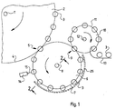
- FIG. 1 shows a top view of one rotating around an axis 1 in the direction of the arrow Beverage filling machine 2, the rotating with the filling machine 2, schematically fills bottles 3 shown with their body size.
- the bottles 3 run on container locations provided at a fixed circumferential distance the circulation circuit 4. Further details of a conventional beverage filling machine are omitted to simplify the drawing.
- the bottles 3 are placed on a transfer star 6 passed, on which they, on the circulation circuit 7 in circumferentially spaced, not shown Container positions held, transported around an axis 8 become.
- the bottles 3 are turned to a rotating one Pass the capping machine 10, on which they turn in circumferentially spaced Container positions on a circulating circuit 11 rotating around an axis 12 Not shown facilities are closed, then to a not further transport device 13 explained in more detail to be handed over.
- a foaming pulse generator 14 is arranged adjacent to the transfer point 5.
- this is provided as a high-pressure water jet injector, who with a thin and sharp high pressure water jet 15 water from injected into the mouths of bottles 3 above.
- the bottles 3 are filled in the beverage filling machine 2 with a beverage containing CO 2 , such as beer.
- a beverage containing CO 2 such as beer.
- the foaming impulse generated by briefly injecting the high-pressure water jet 15 into a bottle 3 leads to the foaming of the beverage.
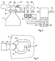
- Figure 2 shows an axial section through the rotating with means not shown driven axis 8 the transfer star, shown in simplified form as a plate 6.
- the cut runs through a container space which, in the exemplary embodiment, as the comparison with the top view in FIG. 3 shows, as a U-shaped pocket 16 is trained.
- the pocket 16 is, as Figure 2 shows, the diameter of the bottle neck adapted and this, the 'usual collar 17 of the bottle 3rd underneath, wear.
- FIG. 2 shows that foam 18 has just started, the mouth of the bottle 3 to exceed. If bottle 3 continues to run, it would probably be Foam keep rising and then run down bottle 3 and contaminate them and at least the transfer star 6.
- the transfer star 6 is at every container location, ie a suction device is provided on each pocket 16. This is shown in FIG. 2 and 3 shown suction nozzle 19, which with its mouth in the immediate vicinity Near the edge of the mouth of the bottle 3 is arranged. Even easier Suction effect of the suction nozzle 19 becomes the one passing over the edge of the bottle Foam 18 sucked off without loss.
- the suction nozzle 19 is connected to a ring line with a line 20 21 connected, which shows schematically as Figure 2, to a bore 22 in the axis 8 is connected.
- a suction device for example a vacuum pump.
- the extracted liquid can be recovered with devices not shown and be returned to the filling process.
- the suction nozzle 19 is greatly widened, slit-shaped trained and adapted to the circumference of the edge of the bottle 3 so that a particularly good and safe suction result.
- the sealing insert 23 shown in Figure 3 It only needs to clean the sealing insert 23 shown in Figure 3 to the Nozzles 19 and 19 'are set sealingly.
- the sealing insert is 23 in not shown with an internal passage between the two Provide suction nozzles. The nozzles can therefore circulate through 22, 21, 20, 19 and through the sealing insert 23 and then further through 19 ', 20', 21 ', 22' in Circuit to be cleaned.
- the container locations on the transfer star 6 are in the embodiment as Pocket 16, so designed to hang neck collar bottles 3, formed. They can also, as usual, encompass the body of the bottle 3 on a stand Bags be formed, the suction nozzles 19 and 19 'in their Height may need to be adjustable to accommodate different container heights to be able to. With appropriate training, the Foam spillage in beverage cans can be prevented.
- the foam is generated with the frothing pulse generator 14 and with the suction nozzles 19, 19 'on the transfer star 6 shown.
- a corresponding device can alternatively also at the container locations the closing machine 10 may be provided in the direction of rotation immediately after the transfer point 9 before starting the containers are closed.
- the described one would be particularly effective, but structurally somewhat more difficult Foaming device on the beverage filling machine 2 in a last, the sector following the filling sector immediately in front of the transfer point 5 provided. There would be the advantage that the containers transported so early be filled with foam in their head space as possible.
- the one or more suction nozzles 19, 19 'located at a container location nearby of the container edge are to be provided, as in FIGS. 2 and 3, laterally as close as possible to the edge of the container. It can, for example, also have a suction nozzle acting centrally from above be provided.
- the suction device has individual, moving suction nozzles 19, 19 'assigned to each container location (pocket 16) on.
- a stationary suction device can also be provided.
- the stationary suction device is a suction bar 25 shown the transfer star 6 on its circumference at the level of the edge the bottle 3 surrounds. It has one along its entire length on the inside edge Suction slot 26, as shown in Figure 2.
- FIG 1 shows, begins the suction bar 25 in the transport direction immediately behind the frothing pulse generator 14 and ends shortly before the transfer point 9 to the sealing machine 10. Since the squeegee 15 is stationary, it can be connected to one in a very simple manner Suction device, not shown, may be connected. It can also be done on simple Be made CIP-capable. For this, e.g. the suction slot 26 to suitable Way to close and the suction bar 25 e.g. at the ends with suction lines to be connected to a cleaning circuit. Also a division into Two parts, similar to the nozzles 19, 19 ', are possible, the two nozzles being in series or can be arranged one above the other.
- suction device spaced apart from one another in a row arranged to form a plurality of suction nozzles, the transfer star surrounded at its circumference at the edge of the bottles, and at which the bottles circulating with the transfer star run past.
Landscapes
- Filling Of Jars Or Cans And Processes For Cleaning And Sealing Jars (AREA)
- Basic Packing Technique (AREA)
Claims (5)
- Dispositif de moussage pour conteneurs à boissons (3) non fermés contenant une boisson gazeuse transportés par un système de transport (6), muni d'un dispositif (14) stationnaire adjoint au système de transport (6) et destiné à générer une courte impulsion de moussage au passage des récipients (3), caractérisé en ce que le dispositif de moussage présente un système d'aspiration (19, 19', 25) agencé sur le système de transport (6) à proximité du bord du goulot des récipients (3) transportés.
- Dispositif selon la revendication 1 pour conteneurs à boissons (3) transportés isolément dans les emplacements pour conteneurs (16) du système de transport (6), caractérisé en ce qu'à chaque emplacement pour conteneurs (16) du système de transport (6) est affecté un système d'aspiration (19, 19') agencé de façon à être entraíné dans la rotation du système de transport.
- Dispositif selon la revendication 1, caractérisée en ce que le système d'aspiration est muni de deux buses d'aspiration (19, 19') branchées sur des conduites d'aspiration séparées (20, 20').
- Dispositif selon la revendication 1, caractérisée en ce que le système d'aspiration (19, 19', 25) est agencé au niveau de l'étoile de transfert (6) entre une soutireuse (2) et une capsuleuse (10).
- Dispositif selon la revendication 1, caractérisée en ce que le système d'aspiration est réalisé sous forme de réglette d'aspiration (25) allongée stationnaire installée à côté du système de transport (6) à proximité du bord du goulot des récipients (3) qui y sont transportés.
Applications Claiming Priority (3)
| Application Number | Priority Date | Filing Date | Title |
|---|---|---|---|
| DE10048761 | 2000-09-29 | ||
| DE10048761A DE10048761C1 (de) | 2000-09-29 | 2000-09-29 | Aufschäumvorrichtung für Getränkebehälter |
| PCT/EP2001/010796 WO2002026613A1 (fr) | 2000-09-29 | 2001-09-19 | Dispositif de moussage pour récipients de boisson |
Publications (2)
| Publication Number | Publication Date |
|---|---|
| EP1226087A1 EP1226087A1 (fr) | 2002-07-31 |
| EP1226087B1 true EP1226087B1 (fr) | 2003-12-10 |
Family
ID=7658411
Family Applications (1)
| Application Number | Title | Priority Date | Filing Date |
|---|---|---|---|
| EP01984551A Expired - Lifetime EP1226087B1 (fr) | 2000-09-29 | 2001-09-19 | Dispositif de moussage pour r cipients de boisson |
Country Status (7)
| Country | Link |
|---|---|
| US (1) | US20030047236A1 (fr) |
| EP (1) | EP1226087B1 (fr) |
| BR (1) | BR0107269B1 (fr) |
| DE (2) | DE10048761C1 (fr) |
| ES (1) | ES2210189T3 (fr) |
| MX (1) | MXPA02005320A (fr) |
| WO (1) | WO2002026613A1 (fr) |
Families Citing this family (1)
| Publication number | Priority date | Publication date | Assignee | Title |
|---|---|---|---|---|
| DE102006022464B4 (de) * | 2006-05-13 | 2008-09-25 | Khs Ag | Verfahren sowie Vorrichtung zum gesteuerten Aufschäumen eines in Flaschen oder dergleichen Behälter eingebrachten Füllgutes |
Family Cites Families (14)
| Publication number | Priority date | Publication date | Assignee | Title |
|---|---|---|---|---|
| US2114964A (en) * | 1935-11-19 | 1938-04-19 | Wallerstein Co Inc | Art of packaging beers and ales |
| US2218911A (en) * | 1937-01-19 | 1940-10-22 | Mckeesport Tin Plate Corp | Jetter for beverage packaging apparatus |
| US2171853A (en) * | 1938-10-14 | 1939-09-05 | Ehrhart J Kurtzbein | Foam remover |
| US2312288A (en) * | 1939-05-27 | 1943-02-23 | Hoffman Beverage Company | Purging air from carbonated beverage containers |
| US2604247A (en) * | 1948-03-03 | 1952-07-22 | Ex Cell O Corp | Defoamer for bottling machines |
| US2672420A (en) * | 1949-07-07 | 1954-03-16 | Pacific Can Company | Apparatus and method for conditioning cans of foaming liquids |
| US2753098A (en) * | 1951-11-05 | 1956-07-03 | Safeway Stores | Defoamer |
| DE2132522A1 (de) * | 1971-06-30 | 1973-01-11 | Seitz Werke Gmbh | Verfahren zum entfernen der luft aus in flaschen abgefuellten getraenken, insbesondere bier |
| CA983448A (en) * | 1973-05-08 | 1976-02-10 | Molson Companies Limited - Les Compagnies Molson Limitee (The) | Air reducing device |
| DE3311200C1 (de) * | 1983-03-26 | 1984-04-05 | Krones Ag Hermann Kronseder Maschinenfabrik, 8402 Neutraubling | Vorrichtung zum Behandeln von Flaschen od.dgl. |
| US4520528A (en) * | 1983-07-27 | 1985-06-04 | James Dole Corporation | Vacuum foam remover |
| US5038548A (en) * | 1983-07-29 | 1991-08-13 | Sieg William F | Defoaming method and apparatus |
| DE3638601A1 (de) * | 1986-11-12 | 1988-05-26 | Seitz Enzinger Noll Masch | Aufschaeumvorrichtung zum verdraengen des restluftvolumens aus mit einem aufschaeumbaren fluessigen fuellgut gefuellten behaeltern, insbesondere flaschen |
| DE4030081A1 (de) * | 1990-09-22 | 1992-03-26 | Seitz Enzinger Noll Masch | Aufschaeumvorrichtung zum verdraengen des restluftvolumens aus mit einem aufschaeumbaren fluessigen fuellgut gefuellten behaeltern, insbesondere flaschen |
-
2000
- 2000-09-29 DE DE10048761A patent/DE10048761C1/de not_active Expired - Fee Related
-
2001
- 2001-09-19 US US10/130,970 patent/US20030047236A1/en not_active Abandoned
- 2001-09-19 BR BRPI0107269-2A patent/BR0107269B1/pt not_active IP Right Cessation
- 2001-09-19 WO PCT/EP2001/010796 patent/WO2002026613A1/fr not_active Ceased
- 2001-09-19 EP EP01984551A patent/EP1226087B1/fr not_active Expired - Lifetime
- 2001-09-19 DE DE50101133T patent/DE50101133D1/de not_active Expired - Lifetime
- 2001-09-19 MX MXPA02005320A patent/MXPA02005320A/es unknown
- 2001-09-19 ES ES01984551T patent/ES2210189T3/es not_active Expired - Lifetime
Also Published As
| Publication number | Publication date |
|---|---|
| EP1226087A1 (fr) | 2002-07-31 |
| DE50101133D1 (de) | 2004-01-22 |
| BR0107269B1 (pt) | 2009-08-11 |
| ES2210189T3 (es) | 2004-07-01 |
| WO2002026613A1 (fr) | 2002-04-04 |
| BR0107269A (pt) | 2002-08-06 |
| DE10048761C1 (de) | 2002-06-06 |
| MXPA02005320A (es) | 2003-10-14 |
| US20030047236A1 (en) | 2003-03-13 |
Similar Documents
| Publication | Publication Date | Title |
|---|---|---|
| DE3515334C2 (de) | Gefäßverschließmaschine | |
| DE19817735C1 (de) | Getränkeabfüllvorrichtung | |
| DE68905749T2 (de) | Aseptische fuellvorrichtung. | |
| DE102008032123A1 (de) | Vorrichtung zum Transportieren von Behältnissen mit Kühlung für die Behältnisse | |
| DE102009008138A1 (de) | Transportsystem für Flaschen oder dergleichen Behälter | |
| DE102011008878A1 (de) | Füllelement für Behälterbehandlungsmaschinen in Form von Füllmaschinen, Behälterbehandlungsmaschine sowie Verfahren zum Reinigen von Maschinenelementen an Behälterbehandlungsmaschinen | |
| DE10246061A1 (de) | Verfahren zum Befüllen von pharmazeutischen Behältnissen wie Ampullen, Vials o.ä. | |
| WO2010037356A1 (fr) | Procédé et dispositif de remplissage | |
| DE3920977A1 (de) | Vorrichtung zum fuellen von behaeltern | |
| EP1424307A1 (fr) | Dispositif pour fermer des récipients | |
| DE10358265A1 (de) | Behälterbehandlungsvorrichtung mit Gasvorhang | |
| DE29708145U1 (de) | Vorrichtung zum Reinigen und/oder Sterilisieren von Verschlußkappen für Flaschen o.dgl. | |
| DE10048761C1 (de) | Aufschäumvorrichtung für Getränkebehälter | |
| DE2363248A1 (de) | Einrichtung zur verringerung des luftanteils bei in flaschen abgefuellten getraenken, insbesondere bei in flaschen abgefuelltem bier | |
| DE3638601A1 (de) | Aufschaeumvorrichtung zum verdraengen des restluftvolumens aus mit einem aufschaeumbaren fluessigen fuellgut gefuellten behaeltern, insbesondere flaschen | |
| DE102014117279A1 (de) | Vorrichtung zum Befüllen eines Behälters mit einem Füllprodukt | |
| EP2289640A1 (fr) | Dispositif de pulvérisation | |
| DE4135438A1 (de) | Vorrichtung zum aufschaeumen von karbonisierten getraenken in flaschen | |
| DE19941456C1 (de) | Füllmaschine mit vakuumbeaufschlagbaren Füllorganen | |
| DE10045932A1 (de) | Verfahren zur Spritzung und Spritzvorrichtung an einer Flaschenreinigungsmaschine | |
| EP0698425A1 (fr) | Machine de lavage pour bouteilles en plastique avec goulots | |
| EP1899258B1 (fr) | Dispositif pour eviter les fluctuations de niveau excessives dans des recipients remplis, lors de leur transport | |
| DE4226616C2 (de) | Vorrichtung zur Behandlung von Behältern vor dem Befüllen | |
| DE4203786A1 (de) | Vorrichtung zum entfernen von scherben gebrochener flaschen bei einer fuellmaschine | |
| DE2527363A1 (de) | Flaschenbehandlungsanlage |
Legal Events
| Date | Code | Title | Description |
|---|---|---|---|
| PUAI | Public reference made under article 153(3) epc to a published international application that has entered the european phase |
Free format text: ORIGINAL CODE: 0009012 |
|
| 17P | Request for examination filed |
Effective date: 20020223 |
|
| AK | Designated contracting states |
Kind code of ref document: A1 Designated state(s): AT BE CH CY DE DK ES FI FR GB GR IE IT LI LU MC NL PT SE TR |
|
| AX | Request for extension of the european patent |
Free format text: AL;LT;LV;MK;RO;SI |
|
| GRAH | Despatch of communication of intention to grant a patent |
Free format text: ORIGINAL CODE: EPIDOS IGRA |
|
| GRAH | Despatch of communication of intention to grant a patent |
Free format text: ORIGINAL CODE: EPIDOS IGRA |
|
| GRAA | (expected) grant |
Free format text: ORIGINAL CODE: 0009210 |
|
| AK | Designated contracting states |
Kind code of ref document: B1 Designated state(s): BE DE ES FR GB IT |
|
| REG | Reference to a national code |
Ref country code: GB Ref legal event code: FG4D Free format text: NOT ENGLISH |
|
| GBT | Gb: translation of ep patent filed (gb section 77(6)(a)/1977) |
Effective date: 20031210 |
|
| REG | Reference to a national code |
Ref country code: IE Ref legal event code: FG4D Free format text: GERMAN |
|
| REF | Corresponds to: |
Ref document number: 50101133 Country of ref document: DE Date of ref document: 20040122 Kind code of ref document: P |
|
| LTIE | Lt: invalidation of european patent or patent extension |
Effective date: 20031210 |
|
| ET | Fr: translation filed | ||
| REG | Reference to a national code |
Ref country code: ES Ref legal event code: FG2A Ref document number: 2210189 Country of ref document: ES Kind code of ref document: T3 |
|
| REG | Reference to a national code |
Ref country code: IE Ref legal event code: FD4D |
|
| PLBE | No opposition filed within time limit |
Free format text: ORIGINAL CODE: 0009261 |
|
| STAA | Information on the status of an ep patent application or granted ep patent |
Free format text: STATUS: NO OPPOSITION FILED WITHIN TIME LIMIT |
|
| 26N | No opposition filed |
Effective date: 20040913 |
|
| REG | Reference to a national code |
Ref country code: FR Ref legal event code: CD Ref country code: FR Ref legal event code: CA |
|
| REG | Reference to a national code |
Ref country code: FR Ref legal event code: TP |
|
| BECA | Be: change of holder's address |
Owner name: *SIDEL G.M.B.H.ALFRED-NOBEL-STRASSE 6, D-68519 VIE Effective date: 20060508 |
|
| BECN | Be: change of holder's name |
Owner name: *SIDEL G.M.B.H. Effective date: 20060508 |
|
| PGFP | Annual fee paid to national office [announced via postgrant information from national office to epo] |
Ref country code: BE Payment date: 20071121 Year of fee payment: 7 |
|
| BERE | Be: lapsed |
Owner name: *SIDEL G.M.B.H. Effective date: 20080930 |
|
| PG25 | Lapsed in a contracting state [announced via postgrant information from national office to epo] |
Ref country code: BE Free format text: LAPSE BECAUSE OF NON-PAYMENT OF DUE FEES Effective date: 20080930 |
|
| PGFP | Annual fee paid to national office [announced via postgrant information from national office to epo] |
Ref country code: IT Payment date: 20100922 Year of fee payment: 10 Ref country code: FR Payment date: 20100921 Year of fee payment: 10 |
|
| PGFP | Annual fee paid to national office [announced via postgrant information from national office to epo] |
Ref country code: GB Payment date: 20100916 Year of fee payment: 10 |
|
| PGFP | Annual fee paid to national office [announced via postgrant information from national office to epo] |
Ref country code: DE Payment date: 20100721 Year of fee payment: 10 |
|
| PGFP | Annual fee paid to national office [announced via postgrant information from national office to epo] |
Ref country code: ES Payment date: 20101018 Year of fee payment: 10 |
|
| GBPC | Gb: european patent ceased through non-payment of renewal fee |
Effective date: 20110919 |
|
| PG25 | Lapsed in a contracting state [announced via postgrant information from national office to epo] |
Ref country code: IT Free format text: LAPSE BECAUSE OF NON-PAYMENT OF DUE FEES Effective date: 20110919 |
|
| REG | Reference to a national code |
Ref country code: FR Ref legal event code: ST Effective date: 20120531 |
|
| REG | Reference to a national code |
Ref country code: DE Ref legal event code: R119 Ref document number: 50101133 Country of ref document: DE Effective date: 20120403 |
|
| PG25 | Lapsed in a contracting state [announced via postgrant information from national office to epo] |
Ref country code: DE Free format text: LAPSE BECAUSE OF NON-PAYMENT OF DUE FEES Effective date: 20120403 |
|
| PG25 | Lapsed in a contracting state [announced via postgrant information from national office to epo] |
Ref country code: FR Free format text: LAPSE BECAUSE OF NON-PAYMENT OF DUE FEES Effective date: 20110930 Ref country code: GB Free format text: LAPSE BECAUSE OF NON-PAYMENT OF DUE FEES Effective date: 20110919 |
|
| REG | Reference to a national code |
Ref country code: ES Ref legal event code: FD2A Effective date: 20130606 |
|
| PG25 | Lapsed in a contracting state [announced via postgrant information from national office to epo] |
Ref country code: ES Free format text: LAPSE BECAUSE OF NON-PAYMENT OF DUE FEES Effective date: 20110920 |