EP1226366B1 - Einwegkupplung - Google Patents
Einwegkupplung Download PDFInfo
- Publication number
- EP1226366B1 EP1226366B1 EP00980093A EP00980093A EP1226366B1 EP 1226366 B1 EP1226366 B1 EP 1226366B1 EP 00980093 A EP00980093 A EP 00980093A EP 00980093 A EP00980093 A EP 00980093A EP 1226366 B1 EP1226366 B1 EP 1226366B1
- Authority
- EP
- European Patent Office
- Prior art keywords
- ring
- clutch according
- ring means
- sleeve
- halves
- Prior art date
- Legal status (The legal status is an assumption and is not a legal conclusion. Google has not performed a legal analysis and makes no representation as to the accuracy of the status listed.)
- Expired - Lifetime
Links
- 230000000295 complement effect Effects 0.000 claims description 2
- 239000000843 powder Substances 0.000 claims description 2
- 239000000463 material Substances 0.000 claims 1
- 238000004519 manufacturing process Methods 0.000 description 2
- 230000005540 biological transmission Effects 0.000 description 1
- 238000010276 construction Methods 0.000 description 1
- 230000008878 coupling Effects 0.000 description 1
- 238000010168 coupling process Methods 0.000 description 1
- 238000005859 coupling reaction Methods 0.000 description 1
- 239000002184 metal Substances 0.000 description 1
- 229910052755 nonmetal Inorganic materials 0.000 description 1
Images

Classifications
-
- F—MECHANICAL ENGINEERING; LIGHTING; HEATING; WEAPONS; BLASTING
- F16—ENGINEERING ELEMENTS AND UNITS; GENERAL MEASURES FOR PRODUCING AND MAINTAINING EFFECTIVE FUNCTIONING OF MACHINES OR INSTALLATIONS; THERMAL INSULATION IN GENERAL
- F16D—COUPLINGS FOR TRANSMITTING ROTATION; CLUTCHES; BRAKES
- F16D41/00—Freewheels or freewheel clutches
- F16D41/12—Freewheels or freewheel clutches with hinged pawl co-operating with teeth, cogs, or the like
-
- F—MECHANICAL ENGINEERING; LIGHTING; HEATING; WEAPONS; BLASTING
- F16—ENGINEERING ELEMENTS AND UNITS; GENERAL MEASURES FOR PRODUCING AND MAINTAINING EFFECTIVE FUNCTIONING OF MACHINES OR INSTALLATIONS; THERMAL INSULATION IN GENERAL
- F16D—COUPLINGS FOR TRANSMITTING ROTATION; CLUTCHES; BRAKES
- F16D41/00—Freewheels or freewheel clutches
- F16D41/18—Freewheels or freewheel clutches with non-hinged detent
Definitions
- the invention is related to a one-way clutch, comprising at least two concentric ring means, one of said ring means carrying at least one ratchet pawl, and the other of said ring means comprising ratchet teeth which engage said at least one ratchet pawl so as to allow relative rotational movement of said at least two ring means in one rotational direction, and to provide a clutch between those ring means in the opposite rotational direction.
- Such one-way clutches are generally known, and are e.g. applied in the automotive field, in particular in automatic transmissions.
- the object of the invention is to provide a one-way clutch having a construction which is improved with respect to stiffness, ease of manufacture and durability.
- This object is achieved in that at least one of said ring means comprises two identical ring halves which are connected to each other and which at least partly enclose a single other ring means at axially opposite ends.
- the ring means which comprises two identical ring halves, is relatively easy and cheap with respect to manufacturing. Moreover, it is possible to provide a sturdy, self-contained unit due to the fact that the other ring means can be enclosed, and therefore be held captive, between the two rings.
- the identical ring halves constitute an inner ring means, each ring half being provided with a radially outwardly extending flange and axially extending sleeve means, said sleeve means fitting together so as to provide a full inner sleeve.
- each ring half comprises at least one axially extending sleeve part which stretches over less than the full circumference of said ring half, said sleeve parts of said ring halves being complementary.
- each sleeve means of each ring half comprises two sleeve parts, which are regularly spaced in circumferential direction.
- the ratchet mechanism which provides a fixed coupling between the ring means in one rotational direction, and which allows relative rotations in the other direction, can be carried out in several ways.
- at least one sleeve part is provided with a radially outwardly extending slot, which accommodates a spring-biassed ratchet pawl.
- the ratchet pawl is freely translatably in radial direction, a blade spring being provided at its radially inner end for constantly urging the ratchet pawl in radially outward direction.
- a ratchet pawl may be provided which is pivotable.
- the outer ring means may comprise an axially extending outer sleeve which surrounds the flanges of both ring halves of the inner ring means, and radially inwardly protruding ratchet teeth accommodated between said flanges.
- one of the ring means may comprise at least one ratchet pawl which is movable in axial direction, and the other ring means may comprise ratchet teeth on a radially extending surface of said other ring means.
- the ring halves of the inner ring means may be provided with mutually aligned, axially extending slots accommodating a spring clip for mutually connecting said rings halves.
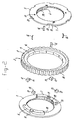
- Figure 1 shows a view in perspective of a part of the one-way clutch according to the invention.
- Figure 2 shows an exploded view
- the one-way clutch as shown in figures 1 and 2 comprises an inner ring means 1 and an outer ring means 2.
- the inner ring means 1 comprises two identical ring halves 3, 4, each being provided with a radially outwardly extending flange 5 and two axially extending sleeve parts 6, 7.
- the outer ring means comprises an axially extending outer sleeve 8, as well as a radially inwardly extending flange 9.
- the inner ring halves 3, 4 are assembled in such a way that the sleeve parts 6, 7 thereof constitute a full inner sleeve 10.
- the ring halves are mutually connected by means of clips 16, inserted in openings 15.
- the inner sleeve 10 comprises radially extending slots 11, accommodating radially translatable ratchet pawls 12, which are biassed by blade springs 13.
- the inwardly protruding flange 9 of the outer ring means 2 comprises ratchet teeth 14, which engage the ratchet pawls 12.
- the inwardly protruding sleeve 9 of the outer ring means 2 is accommodated between the flanges 5 of the ring halves 3, 4.
- the ring means 1, 2 are provided with splines 18, 19 for connecting them to e.g. a shaft.
- the ring means 1, 2 may be formed either of a metal or a non-metal. In particular powder forming may be applied.
- At least one of the ring means 1, 2 is provided with surface grooves 20 for supplying oil to the ratchet teeth 14 and/or ratchet pawl(s) 12.
- the ring means 1, 2 may be lubricated and sealed for life.
Landscapes
- Engineering & Computer Science (AREA)
- General Engineering & Computer Science (AREA)
- Mechanical Engineering (AREA)
- Mechanical Operated Clutches (AREA)
Claims (14)
- Einwegkupplung mit mindestens zwei konzentrischen Ringelementen (1, 2), hierbei trägt eines dieser Ringelemente (1) mindestens eine Sperrklinke (12) und das andere dieser Ringelemente (2) weist Sperrzähne (14) auf, welche in die mindestens eine Sperrklinke (12) einrasten, so dass eine relative Drehbewegung der mindestens zwei Ringelemente (1, 2) in einer Drehrichtung möglich ist und eine Kupplung zwischen diesen Ringelementen (1, 2) in der gegenläufigen Drehrichtung vorliegt, dadurch gekennzeichnet, dass mindestens einer dieser Ringelemente aus zwei identischen Ringhälften (3, 4) enthält, die miteinander verbunden sind und mindestens teilweise ein einziges anderes Ringelement (2) an gegenüberliegenden axialen Enden umschließen.
- Kupplung nach Anspruch 1, wobei sich die identischen Ringhälften (3, 4) aus einem inneren Ringelement (1) aufbauen, jede Ringhälfte (3, 4) einen sich radial nach außen erstreckenden Flansch (5) und axial verlaufende Buchsenelemente (6, 7) aufweist, die Buchsenelemente (6, 7) so zusammenpassen, dass eine volle Innenbuchse (10) gebildet wird.
- Kupplung nach Anspruch 2, wobei die Buchsenelemente (6, 7) jeder Ringhälfte (3, 4) aus mindestens einem sich axial erstreckenden Buchsenabschnitt (6, 7) aufweisen, der sich über weniger als den Gesamtumfang der Ringhälfte (3, 4) erstreckt und diese Buchsenabschnitte (6, 7) der Ringhälften (3, 4) komplementär sind.
- Kupplung nach Anspruch 3, wobei jedes Buchsenelement (6, 7) jeder Ringhälfte (3, 4) zwei Buchsenabschnitte (6, 7) aufweist, die regelmäßig in Umfangsrichtung angeordnet sind.
- Kupplung nach Anspruch 3 oder 4, wobei mindestens ein Buchsenabschnitt (6, 7) eine radial nach außen verlaufende Aussparung (11) aufweist, der eine vorgespannte Federsperrklinke (12) aufnimmt.
- Kupplung nach Anspruch 5, wobei die Sperrklinke (12) frei in radialer Richtung verschiebbar ist, eine (Blatt-)Feder (13) ist an ihrer radialen Innenseite vorgesehen, um konstant die Sperrklinke (12) in radialer Richtung nach Außen zu drücken.
- Kupplung nach einem der Ansprüche 3 - 6, wobei das äußere Ringelement (2) eine sich axial erstreckende äußere Buchse (8) aufweist, die die Flansche (5) beider Ringhälften (3, 4) umgibt und radial nach Innen vorspringende Sperrzähne (14), welche zwischen den Flanschen (5) angeordnet sind.
- Kupplung nach Anspruch 1 oder 2, wobei eines der Ringelemente mindestens eine Sperrklinke aufweist, die in axialer Richtung verschiebbar ist und das andere Ringelement Sperrzähne auf einer sich radial erstreckenden Oberfläche des anderen Ringelementes hat.
- Kupplung nach einem der vorherigen Ansprüche, wobei die Ringhälften (3, 4) mit zueinander ausgerichteten, axial verlaufenden Schlitzen (15) versehen sind, die eine Sprungfeder (16) aufnehmen, um die Ringhälften (3, 4) miteinander zu verbinden.
- Kupplung nach einem der vorherigen Ansprüche, wobei das äußere Ringelement (18) Antriebsmittel (19) wie Rillen und/oder Nuten auf seiner Außenfläche aufweist.
- Kupplung nach einem der vorherigen Ansprüche, wobei das innere Ringelement (18) Antriebsmittel (19) wie Rillen und/oder Nuten auf seiner Innenfläche aufweist.
- Kupplung nach einem der vorherigen Ansprüche, wobei mindestens eines der Ringelemente (1, 2) aus Pulvermaterial hergestellt ist.
- Kupplung nach einem der vorherigen Ansprüche, wobei mindestens eines der Ringelemente (1, 2) mit Oberflächennuten (20) versehen ist, um die Sperrzähne (14) und/oder Sperrklinke(n) (12) mit Öl zu versorgen.
- Kupplung nach einem der vorherigen Ansprüche, wobei die Ringelemente (1, 2) gegeneinander mittels einer Spaltdichtung abgedichtet sind.
Applications Claiming Priority (3)
| Application Number | Priority Date | Filing Date | Title |
|---|---|---|---|
| NL1013449 | 1999-11-01 | ||
| NL1013449A NL1013449C2 (nl) | 1999-11-01 | 1999-11-01 | Eenwegkoppeling. |
| PCT/NL2000/000789 WO2001033092A1 (en) | 1999-11-01 | 2000-11-01 | One-way clutch |
Publications (2)
| Publication Number | Publication Date |
|---|---|
| EP1226366A1 EP1226366A1 (de) | 2002-07-31 |
| EP1226366B1 true EP1226366B1 (de) | 2004-10-13 |
Family
ID=19770175
Family Applications (1)
| Application Number | Title | Priority Date | Filing Date |
|---|---|---|---|
| EP00980093A Expired - Lifetime EP1226366B1 (de) | 1999-11-01 | 2000-11-01 | Einwegkupplung |
Country Status (7)
| Country | Link |
|---|---|
| US (1) | US6691848B1 (de) |
| EP (1) | EP1226366B1 (de) |
| JP (1) | JP4579477B2 (de) |
| AU (1) | AU1739401A (de) |
| DE (1) | DE60014946T2 (de) |
| NL (1) | NL1013449C2 (de) |
| WO (1) | WO2001033092A1 (de) |
Families Citing this family (4)
| Publication number | Priority date | Publication date | Assignee | Title |
|---|---|---|---|---|
| GB0215727D0 (en) * | 2002-07-06 | 2002-08-14 | Lucas Industries Ltd | No-back device |
| GB201105163D0 (en) | 2010-08-30 | 2011-05-11 | American Grease Stick Co | Wrench ratchet mechanisms and wrenches |
| TW201729951A (zh) * | 2015-11-04 | 2017-09-01 | 奈傑爾 亞歷山大 布坎南 | 棘輪扳手 |
| EP3786474A1 (de) * | 2019-08-27 | 2021-03-03 | Hilti Aktiengesellschaft | Formschlüssige freilaufkupplung |
Family Cites Families (17)
| Publication number | Priority date | Publication date | Assignee | Title |
|---|---|---|---|---|
| US1452316A (en) * | 1922-03-11 | 1923-04-17 | William M Shirley | Differential gear |
| US2014383A (en) * | 1931-10-21 | 1935-09-17 | Harry A Knox | Power transmission mechanism |
| US1955200A (en) * | 1931-11-13 | 1934-04-17 | Christine Millican | Rotary clutch |
| US2010528A (en) * | 1933-12-02 | 1935-08-06 | Schofield | Ratchet device |
| DE6800671U (de) * | 1968-10-02 | 1969-01-23 | Skf Kugellagerfabriken Gmbh | Abgedichtetes waelzlager, insbesondere vollrolliges zylinderrollenlager |
| US3918776A (en) * | 1972-06-29 | 1975-11-11 | Borg Warner | Roller bearing assembly |
| MX146440A (es) * | 1978-01-02 | 1982-06-28 | Hector Mendoza Orozco | Mejoras en mecanismo de rueda libre |
| US4453729A (en) * | 1982-09-20 | 1984-06-12 | Lucken Wesley O | Occupant propellable wheelchair |
| JPS5962331U (ja) * | 1982-10-20 | 1984-04-24 | 本田技研工業株式会社 | ワンウエイクラツチ付ホイ−ル装置 |
| DE8915895U1 (de) * | 1989-11-09 | 1991-12-05 | MAN Nutzfahrzeuge AG, 8000 München | Doppelgelenklager |
| JPH0650360A (ja) * | 1992-07-30 | 1994-02-22 | Mitsubishi Materials Corp | ワンウェイクラッチ用焼結鍛造インナーレースおよび焼結鍛造アウターレース |
| US5449057A (en) * | 1993-10-26 | 1995-09-12 | Frank; Arthur R. | One-way clutch apparatus |
| US5573094A (en) * | 1995-03-07 | 1996-11-12 | Gte Government Systems Corporation | Combination bearing/freewheel clutch |
| US5966581A (en) * | 1996-08-30 | 1999-10-12 | Borg-Warner Automotive, Inc. | Method of forming by cold worked powdered metal forged parts |
| US5853073A (en) * | 1996-09-03 | 1998-12-29 | Borg-Warner Automotive, Inc. | Ratchet one-way clutch assembly |
| CN1068662C (zh) * | 1997-11-01 | 2001-07-18 | 黄金伦 | 啮合式超越离合器 |
| US6065576A (en) * | 1998-03-20 | 2000-05-23 | Means Industries, Inc. | Strut for planar one-way clutch |
-
1999
- 1999-11-01 NL NL1013449A patent/NL1013449C2/nl not_active IP Right Cessation
-
2000
- 2000-11-01 DE DE60014946T patent/DE60014946T2/de not_active Expired - Fee Related
- 2000-11-01 US US10/110,969 patent/US6691848B1/en not_active Expired - Fee Related
- 2000-11-01 JP JP2001535749A patent/JP4579477B2/ja not_active Expired - Fee Related
- 2000-11-01 AU AU17394/01A patent/AU1739401A/en not_active Abandoned
- 2000-11-01 WO PCT/NL2000/000789 patent/WO2001033092A1/en not_active Ceased
- 2000-11-01 EP EP00980093A patent/EP1226366B1/de not_active Expired - Lifetime
Also Published As
| Publication number | Publication date |
|---|---|
| DE60014946T2 (de) | 2005-10-13 |
| AU1739401A (en) | 2001-05-14 |
| EP1226366A1 (de) | 2002-07-31 |
| JP2003532841A (ja) | 2003-11-05 |
| WO2001033092A1 (en) | 2001-05-10 |
| JP4579477B2 (ja) | 2010-11-10 |
| DE60014946D1 (de) | 2004-11-18 |
| US6691848B1 (en) | 2004-02-17 |
| NL1013449C2 (nl) | 2001-05-02 |
Similar Documents
| Publication | Publication Date | Title |
|---|---|---|
| CN1831359B (zh) | 含超越制动器的自动变速装置托架总成 | |
| US5853073A (en) | Ratchet one-way clutch assembly | |
| US7854306B2 (en) | Clutch assembly with an oil pump clutch housing and a carrier engaged with a clutch pack outer circumference | |
| US7878316B2 (en) | High torque one way clutch | |
| EP2882973B1 (de) | Entkopplerträger mit ausgeglichener kräften | |
| US7416067B2 (en) | Power transmission unit | |
| US9651099B2 (en) | Clutched device with wrap spring clutch with overrun locking member | |
| JP4184670B2 (ja) | ラチェットワンウェイクラッチを用いたステータ装置 | |
| GB2443939A (en) | Retention of an actuating spring in a one-way clutch | |
| US20110315505A1 (en) | Aluminum clutch housing for a friction clutch with a piston pocket and a spline liner | |
| US6557682B2 (en) | One-way clutch | |
| JP2009531608A (ja) | 統合されたステータを有する一方向クラッチ | |
| WO2022260873A1 (en) | Dog clutch with ratcheting one-way clutch | |
| JP5063027B2 (ja) | 半径方向に重ねて配置されるクラッチ配置構造 | |
| EP1226366B1 (de) | Einwegkupplung | |
| JP2013536389A (ja) | クイックリリース機能を備えたラップスプリングクラッチ結合器 | |
| JP6416116B2 (ja) | オーバーランモードおよび保持された制御要素を有する、制御可能式または選択可能式のカップリングアセンブリ | |
| US5634542A (en) | Friction clutch with a flywheel | |
| EP0575037B1 (de) | Klemmkörpereinwegkupplung | |
| US6035993A (en) | Friction clutch with pre-damper | |
| JPH09112568A (ja) | トルクリミッタおよびクラッチ | |
| US6830138B2 (en) | Stator | |
| US4947969A (en) | Center load clutch brake | |
| GB2343234A (en) | Torsion vibration damper | |
| JP2003028205A (ja) | ラチェットワンウェイクラッチ及びラチェットワンウェイクラッチを用いたステータ |
Legal Events
| Date | Code | Title | Description |
|---|---|---|---|
| PUAI | Public reference made under article 153(3) epc to a published international application that has entered the european phase |
Free format text: ORIGINAL CODE: 0009012 |
|
| 17P | Request for examination filed |
Effective date: 20020416 |
|
| AK | Designated contracting states |
Kind code of ref document: A1 Designated state(s): AT BE CH CY DE DK ES FI FR GB GR IE IT LI LU MC NL PT SE TR |
|
| AX | Request for extension of the european patent |
Free format text: AL;LT;LV;MK;RO;SI |
|
| GRAP | Despatch of communication of intention to grant a patent |
Free format text: ORIGINAL CODE: EPIDOSNIGR1 |
|
| RBV | Designated contracting states (corrected) |
Designated state(s): AT BE CH CY DE FR GB IT LI |
|
| RBV | Designated contracting states (corrected) |
Designated state(s): DE FR GB IT |
|
| GRAS | Grant fee paid |
Free format text: ORIGINAL CODE: EPIDOSNIGR3 |
|
| GRAA | (expected) grant |
Free format text: ORIGINAL CODE: 0009210 |
|
| AK | Designated contracting states |
Kind code of ref document: B1 Designated state(s): DE FR GB IT |
|
| REG | Reference to a national code |
Ref country code: GB Ref legal event code: FG4D |
|
| REG | Reference to a national code |
Ref country code: IE Ref legal event code: FG4D |
|
| REF | Corresponds to: |
Ref document number: 60014946 Country of ref document: DE Date of ref document: 20041118 Kind code of ref document: P |
|
| LTIE | Lt: invalidation of european patent or patent extension |
Effective date: 20041013 |
|
| ET | Fr: translation filed | ||
| PLBE | No opposition filed within time limit |
Free format text: ORIGINAL CODE: 0009261 |
|
| STAA | Information on the status of an ep patent application or granted ep patent |
Free format text: STATUS: NO OPPOSITION FILED WITHIN TIME LIMIT |
|
| 26N | No opposition filed |
Effective date: 20050714 |
|
| PGFP | Annual fee paid to national office [announced via postgrant information from national office to epo] |
Ref country code: IT Payment date: 20071127 Year of fee payment: 8 |
|
| PGFP | Annual fee paid to national office [announced via postgrant information from national office to epo] |
Ref country code: GB Payment date: 20071128 Year of fee payment: 8 |
|
| PGFP | Annual fee paid to national office [announced via postgrant information from national office to epo] |
Ref country code: DE Payment date: 20071221 Year of fee payment: 8 |
|
| GBPC | Gb: european patent ceased through non-payment of renewal fee |
Effective date: 20081101 |
|
| PG25 | Lapsed in a contracting state [announced via postgrant information from national office to epo] |
Ref country code: IT Free format text: LAPSE BECAUSE OF NON-PAYMENT OF DUE FEES Effective date: 20081101 |
|
| PG25 | Lapsed in a contracting state [announced via postgrant information from national office to epo] |
Ref country code: DE Free format text: LAPSE BECAUSE OF NON-PAYMENT OF DUE FEES Effective date: 20090603 |
|
| PG25 | Lapsed in a contracting state [announced via postgrant information from national office to epo] |
Ref country code: GB Free format text: LAPSE BECAUSE OF NON-PAYMENT OF DUE FEES Effective date: 20081101 |
|
| PGFP | Annual fee paid to national office [announced via postgrant information from national office to epo] |
Ref country code: FR Payment date: 20121219 Year of fee payment: 13 |
|
| REG | Reference to a national code |
Ref country code: FR Ref legal event code: ST Effective date: 20140731 |
|
| PG25 | Lapsed in a contracting state [announced via postgrant information from national office to epo] |
Ref country code: FR Free format text: LAPSE BECAUSE OF NON-PAYMENT OF DUE FEES Effective date: 20131202 |