EP1226765A2 - Méthode et appareil pour fabriquer des filtres à plusieurs compartiments - Google Patents
Méthode et appareil pour fabriquer des filtres à plusieurs compartiments Download PDFInfo
- Publication number
- EP1226765A2 EP1226765A2 EP01130104A EP01130104A EP1226765A2 EP 1226765 A2 EP1226765 A2 EP 1226765A2 EP 01130104 A EP01130104 A EP 01130104A EP 01130104 A EP01130104 A EP 01130104A EP 1226765 A2 EP1226765 A2 EP 1226765A2
- Authority
- EP
- European Patent Office
- Prior art keywords
- filter
- sleeve
- drum
- processing station
- sleeves
- Prior art date
- Legal status (The legal status is an assumption and is not a legal conclusion. Google has not performed a legal analysis and makes no representation as to the accuracy of the status listed.)
- Granted
Links
Images


Classifications
-
- A—HUMAN NECESSITIES
- A24—TOBACCO; CIGARS; CIGARETTES; SIMULATED SMOKING DEVICES; SMOKERS' REQUISITES
- A24C—MACHINES FOR MAKING CIGARS OR CIGARETTES
- A24C5/00—Making cigarettes; Making tipping materials for, or attaching filters or mouthpieces to, cigars or cigarettes
- A24C5/47—Attaching filters or mouthpieces to cigars or cigarettes, e.g. inserting filters into cigarettes or their mouthpieces
- A24C5/475—Attaching filters or mouthpieces to cigars or cigarettes, e.g. inserting filters into cigarettes or their mouthpieces adapted for composite filters
-
- A—HUMAN NECESSITIES
- A24—TOBACCO; CIGARS; CIGARETTES; SIMULATED SMOKING DEVICES; SMOKERS' REQUISITES
- A24D—CIGARS; CIGARETTES; TOBACCO SMOKE FILTERS; MOUTHPIECES OF CIGARS OR CIGARETTES; MANUFACTURE OF TOBACCO SMOKE FILTERS OR MOUTHPIECES
- A24D3/00—Tobacco smoke filters, e.g. filter tips or filtering inserts; Filters specially adapted for simulated smoking devices; Mouthpieces of cigars or cigarettes
- A24D3/02—Manufacture of tobacco smoke filters
- A24D3/0204—Preliminary operations before the filter rod forming process, e.g. crimping, blooming
- A24D3/0212—Applying additives to filter materials
- A24D3/0225—Applying additives to filter materials with solid additives, e.g. incorporation of a granular product
-
- A—HUMAN NECESSITIES
- A24—TOBACCO; CIGARS; CIGARETTES; SIMULATED SMOKING DEVICES; SMOKERS' REQUISITES
- A24D—CIGARS; CIGARETTES; TOBACCO SMOKE FILTERS; MOUTHPIECES OF CIGARS OR CIGARETTES; MANUFACTURE OF TOBACCO SMOKE FILTERS OR MOUTHPIECES
- A24D3/00—Tobacco smoke filters, e.g. filter tips or filtering inserts; Filters specially adapted for simulated smoking devices; Mouthpieces of cigars or cigarettes
- A24D3/02—Manufacture of tobacco smoke filters
- A24D3/0275—Manufacture of tobacco smoke filters for filters with special features
- A24D3/0287—Manufacture of tobacco smoke filters for filters with special features for composite filters
Definitions
- the invention relates to a method for producing Multiple filters and a device for manufacturing of multiple filters for tobacco processing products Industry, the device being a filter sleeve feed element, at least one transport element in which Filter sleeves can be inserted and by means of which Filter sleeves of at least one processing station are fed, includes.
- the invention further relates to the use of pre-assembled filter sleeves for Manufacture of multiple filters for tobacco processing products Industry, a corresponding filter sleeve for the production of multiple filters for products of tobacco processing industry and a multiple filter manufacturing system for tobacco processing products Industry that uses a filter cartridge feeder Feeding filter sleeves and a transport system to the Transporting the filter sleeves on a predeterminable Trajectory includes.
- Method and device for producing multiple filters are, for example, from DE-AS 17 82 364 of the applicant, the a device for producing filter granules containing filters with the name "Bernhard” der Applicant who is known in specialist circles describes.
- DE-AS 17 82 364 corresponds to GB 1,243,977 and US 3,603,058 multiple filters, also multi-segment filters are made up of at least two filter elements and typically up to eight filter elements, which can be in any order. In a sleeve formed into a tube will be different Filter elements or segments arranged.
- these can its soft filter elements, such as cellulose acetate, paper, Fleece or relatively hard filter elements such as granules, sintered elements, hollow cylinders or hollow chambers and Capsules and the like.
- the corresponding filter materials do not have to be 100% made of one material.
- This can for example also be mixed materials such as a Granules in a cellulose acetate.
- granular materials such as activated carbon.
- DE-AS 17 82 364 is a granule filling machine known filters containing granules and in particular Produces triple filters. Under triple filter is understood a filter that represents a filter that consists of there are three filter segments, the filling machine "Bernhard” a triple filter twice the working length manufactures, which then for cigarette production between two elongated ones wrapped in cigarette paper Articles containing tobacco are arranged to be in the Middle to be cut so that two with filters provided cigarettes arise.
- DE-AS 17 82 364 is a continuously rotating conveyor with recordings for filter sleeves disclosed, the filter sleeves transversely axially.
- filter plugs that last from a longer one Filter rod are cut off and granules in the Introduced sleeve.
- the filter plugs are transferred namely plunger, inserted into the sleeve.
- the granules fall under the influence of gravity in the sleeve.
- the inventive method it is possible Filter manufacturing speed of a filter manufacturing machine to increase significantly.
- the term “multiple filter” also includes the term “Multi-segment filter”, with at least two segments in the filter are included.
- the segments can be of different types Materials like cellulose acetate, Paper, fleece, granules, sintered elements, hollow cylinders or hollow chambers, capsules, etc.
- Invention will be at least two segments essentially formed simultaneously in the filter sleeve. It So this is the training of several Segments by transferring multiple servings of Filter material.
- the filter sleeve is in an insertion process fully filled or always in two portions or triple portions, in which preferably at the bottom a soft element, such as cellulose acetate, paper and the like. and a granulate or more another soft element is arranged above it.
- a final method step can also preferably be carried out be carried out in which only one Filter material in one portion in the filter sleeve is introduced.
- a Filter sleeve provided and / or manufactured.
- the filter sleeve is exclusively from one side filled, creating a simple design a corresponding device for the production of Multiple filters for tobacco processing products Industry is possible.
- the filling speed be further increased. This is preferred one half each with a filling step or in several filling steps in which packages, through which several segments are formed be filled up.
- the filter sleeve is preferably used to fill two Pages turned.
- the feed is Filter sleeve preferably designed such that in the A filter element is arranged in the middle. So it will preferably with a pre-assembled filter sleeve a filter element in the middle.
- the filter sleeve for filling on a Predeterminable trajectory at least partially transversely led, resulting in a quick procedure and simple constructive elements of a corresponding Have the furnishings implemented.
- the filter material is inserted with a vertical motion component.
- the filter sleeve is preferably formed in a preceding method step.
- the filter sleeve is preferably wrapping material sections or tubular wrappings formed into tubes.
- the filter material segments are or are preferably Filter material segments formed, the alternating granular material and, in particular gas-permeable, limiting pieces, such as soft elements made of cellulose acetate, paper or nonwoven or the like. exhibit.
- An n-fold multiple filter is preferably formed, where n is a natural even number that is greater than 1.
- An n-fold multiple filter means a filter n times the working length. So this is an n-fold multiple filter, where the "multiple" stands for several segments.
- a multiple filter is preferably according to one of the ones described above Process manufactured.
- the invention is further through a device for Manufacture of multiple filters for tobacco processing products
- a filter cartridge feeder and at least one transport element, in the filter sleeves can be inserted and by means of which Filter sleeves can be fed to at least one processing station are solved, which is further developed in that at least two in at least one processing station Portions of the filter materials in one processing step can be inserted into at least one filter sleeve. Preferably two portions can be inserted, if the servings in one processing station in more are insertable as a filter sleeve.
- Design of the facility for manufacturing of multiple filters is a very quick procedure possible.
- a rotating device for rotating the Filter sleeve provided as a processing station.
- the filling be done even faster because the movements, the feed or filling organs must carry out, can be kept relatively short.
- the at least one processing station on a single Arranged conveyor can be a very compact Furnishings can be realized.
- a modular structure is possible if the conveyors have at least one processing station assigned. If the sponsors maximum a processing station is assigned is a particularly modular structure of the facility.
- a plurality of conveyors are preferably provided, of which at least one at least one processing station is assigned, and of which at least one is only one Processing station is assigned.
- a filter material feed station is preferably provided, these two rotatable and eccentrically arranged Comprises disks, each having bores, the holes of one disc and the holes the other disc in one place can be aligned.
- this filter material feed station is a very accurate dosage of For example, filter granulate possible.
- At least one filter material feed station provided, these at least one sliding element, which is provided with holes, and / or at least one lever element provided with holes is included.
- this filter material feed station is a simple and quick handling of filter material possible.
- a particularly simple implementation of the invention Setup is given when a filter material loading station is provided, the at least one first transfer means, in particular at least one Tappet, which comprises at least two portions of the filter materials in one step in the filter sleeve brings.
- the filter material insertion station can preferably with a filter material feed station overlap.
- At least one second transfer means provided that from the opposite side the filter sleeve as a counter bearing to the at least one first transfer means acts.
- the transfer agent can even filter material into the filter sleeve introduce this does not necessarily have to.
- At least one filter sleeve with at least two holes can be aligned axially.
- the invention is further accomplished by a multiple filter manufacturing system for tobacco processing products Industry with a filter sleeve feeder for Feeding filter sleeves and a transport system to the Transporting the filter sleeves on a predeterminable Trajectory and at least one processing station solved, which is further developed in that in the at least one processing station in one processing step at least two servings of the filter material can be introduced into at least one filter sleeve.
- filter manufacturing system Provided portions of filter material in several filter sleeves be introduced or can be introduced preferably at least two servings of each Filter materials introduced or can be introduced.
- the filter manufacturing system further developed that as a processing station Rotating device provided for rotating the filter sleeves is.
- This preferred configuration of the filter production system can be a particularly fast procedure to be possible. If preferably that Transport system at least one continuously rotating Has conveyor, the filter sleeves axially is a particularly simple implementation of the Filter manufacturing system possible.
- the at least one processing station assigned to at least one sponsor is one modular design possible.
- a very compact filter manufacturing system is given if preferred a single conveyor is provided, at least a processing station is assigned.
- a special one A highly modular system is given when several sponsors are provided, each of which at most a processing station is assigned.
- the one manufactured and distributed by the applicant Filter manufacturing machine or device for manufacturing of multiple filters for tobacco processing products Industry provides approximately 1,200 double filters Length of use. With the device according to the invention it is possible to have 5,000 multiple filters in duplicate Manufacture working length. The advantage of the invention The solution is particularly clear.
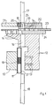
- FIG. 1 shows a cross-sectional illustration of a transfer station.
- a filter plug 20 which can consist, for example, of cellulose acetate.
- the filter plug 20 has a length of 8 mm, for example.
- the Filter plug 20 is by means of a filter plug conveyor 21, e.g. a filter plug drum, in which the Corresponding filter plugs 20 included in the recordings are fed to a plug receptacle 25.
- the filter sleeve 11 is engaged with the transfer station and is by means of vacuum bores 13, which are arranged on a conveyor drum in the specified Location held. It is also a plunger 18 from already been introduced into the filter sleeve 11 below. Furthermore, the plug 20 is through the filter plug conveyor 21 is conveyed to the transfer unit been and is by means of another vacuum drilling 13 held in the position shown in FIG. 2. Furthermore, two different granules, namely a first granulate 26 and a second granulate 27 in provided holes 14 of a slide 24 filled. The amount of granules is determined by the size of the hole given.
- the slider 24 is in the plane of the drawing from left to right to the right and vice versa.
- FIG. 3 shows a cross-sectional view of the transfer station
- the plunger 18 further up was moved vertically so that the sleeve 11 with its upper end essentially flush with the upper Edge of the conveyor drum 12 completes.
- the Stopper 20 by means of the plunger 17 in the axial direction the plunger, i.e. vertically downwards, into the pipe 15 and conveyed into a 1st bore 14 of the slide 23 Service.
- a circular knife 28, which in the guide 29th is cut exactly on the upper edge of the Slider 23 the plug 20 in two equally large plugs each with a length of 4 mm.
- a next process step which is shown in FIG is shown, the slide 23 is pushed to the left, so that the upper part of the split plug 20 with another bore 14 of the slide 23 vertically flees.
- the plug 20 by means of the plunger 17 transferred into the further hole and another Filter plug 30, which is made of a different material e.g. fleece enriched with granules, fed, cut by means of a circular knife and in the two remaining bores 14 of the slide 23 introduced.
- 5 shows exactly the state of the process shown in which the further filter plugs 30 in the remaining holes were introduced.
- the 1st Granules 26 fall into because of gravity Sleeve 11.
- the sleeve 11 will oscillate added.
- a vibration exciter 44 is provided, which causes a spring plate 43 to vibrate by mechanical contact of the spring plate 44 with the Sleeve 11 are transferred to this.
- FIG. 5 is a bore of the slide 23, in which is a filter plug 30 and a bore of the slide 24, in which granules are located, in alignment with the conveyor drum bore 16 or the sleeve 11 aligned so that in a next process step, which is shown in Fig. 6, the plunger 17th the filter material 30 and 26 in the filter sleeve 11 can introduce. It is possible instead, as in Fig. 6 was shown, the filter material 30 and 26 only up to introduce to the upper edge of the filter plug 11, so that the or the degree of movement of the plunger 17th have it minimized.
- FIG. 7 shows the process state in which after appropriate alignment, a hole, in which a filter plug 20 is arranged and a bore of the slide 24, in which the granules 27th is arranged, aligned with the sleeve 11 is so that the plunger 17 could insert the material.
- FIG. 8 shows the stage of the process in which the sleeve 11, half filled with filter material was moved down by lowering the plunger 18 was again in the effective range of the Vacuum bore 13, so that the sleeve 11 back to this Vacuum holes and corresponding to those in the conveyor drum 12 scheduled recordings is held.
- Next up Step is the half-filled sleeve of a turning drum fed to then the sleeve turned by 180 ° to undergo the same procedural steps so that a total of a five-fold filter twice the length of use can be manufactured.
- This quintuple filter includes then five different ones in this embodiment Filter materials in segments in the filter are arranged.
- first Filter material 19 for example a length of 8 mm
- Cutting the filter twice the length of use comprises a first granulate 26 with a height of approx. 8 mm, a second filter plug 30 with a height of 4 mm or a thickness of 4 mm, a second granulate 27 with a height of approx. 8 mm and a final one Filter plug 20 with a thickness of 4 mm.
- filter plugs from to use down to a thickness of 2 mm, so that even more filter materials in segments in the Filter sleeve 11 can be arranged.
- FIG. 8 shows a discharge drum 50, which conveys the half-filled sleeve 11 to a turning drum, which is not shown in Fig. 8.
- the sleeve is then turned through 180 ° in this turning drum turned and then by means of a feed drum Conveyor drum 12 is fed back to the rest of the sleeve 11 to fill.
- To produce filter material 19 can, for example Machine of the applicant, namely the Mulfi E accordingly can be set.
- PVA glue polyvinyl acetate glue
- the cooling bar that glues the seam is replaced by a Heating element replaced.
- the glue supply will also be appropriate replaced.
- the filter sleeve comes with a Glue stuck, which does not become detached by heating the glue connection leads.
- the segment bonding i.e. the gluing of the later inserted filter segments is done in such a way that a hot melt adhesive tape on the Paper is applied inside the sleeve, before the sleeve is molded.
- the entire sleeve warmed either by contact heat or with appropriate high-energy radiation, e.g. Microwave radiation, with which the hot melt adhesive for Melt is brought and the segments glued become.
- FIG. 9 shows a further embodiment according to the invention a transfer device in which at the same time transfer four different filter materials into the sleeve can be.
- the sleeve is, for example. from a paper tube 37.
- a third slide 41 and a fourth slide 42 is provided.
- a soft element 30 is inserted and a granulate 26 in the fourth slide 42.
- Number of holes in the slide 24 of the exemplary embodiments 1 to 8 to four, so that four holes are filled with the appropriate granulate and so that no further granulate filling after the It is necessary to turn or turn the filter sleeve.
- FIGS. 1 to 8 are already appropriate filter plugs 20 and 30 stocked so that after filling one side of the filter sleeve 11 none another filter plug inserted into the slider 23 Need to become. The same is of course also the case with Embodiment according to Fig. 9 possible.
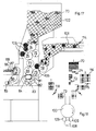
- FIG. 10 is a side view in the upper region (FIG. 10b) a cross-sectional view of a granulate feed station or a granulate portioning station shown.
- a first disc 31 and a second Disc 32 shown, the first disc 31st is arranged above the second disc 32.
- 10b shows a top view of this device. Both disks, 31 and 32, have holes 14 on.
- Granules 26 are filled into the bores.
- the first disc 31 rotates counterclockwise over the disc 32, which in this embodiment is also counterclockwise rotates.
- On the second disc 32 are below this disc sleeves 11 arranged.
- a vibration exciter 44 and a Spring plate 43 is provided, by means of which the sleeve 11 when or after filling with the granules 26 in vibrations is transferred.
- the vibration exciter 44 is preferably an electromagnet with a mass with oscillates at a frequency of 50 Hz.
- FIG. 11 is a schematic plan view of a Filter manufacturing machine shown. It is in Fig. 11 but not the processing stations, which are shown in FIGS. 1 to 9, for example those responsible for inserting the filter elements are provided.
- a sleeve mass flow 101 carries sleeves 114 4 times the length of use to the filter manufacturing machine.
- the Filter sleeves cut 4 times the length of use in the middle and moved axially.
- a transfer cone drum 104 and a transfer drum 105 which e.g. 1 corresponds to the sleeve feed drum 10 the fed sleeves of the main drum 100, e.g. 1 corresponds to the conveyor drum 12.
- a filter element mass flow 102 carries filter elements 12 times the processing length of the filter manufacturing machine to. Some of these are not shown here cut into shorter sections.
- a Transfer cone drum 104 e.g. the filter plug conveyor 21 corresponds to FIG. 1, the filter elements or the already cut filter elements 116 fed to a transfer drum 105 on which it be further divided by means of a circular knife 106.
- a transfer drum 105 On which it be further divided by means of a circular knife 106.
- the granules are via appropriate conveying elements of a granulate transfer station 112 supplied, in the corresponding Drilling slide valves full of the desired granulate can be filled.
- the main drum 100 moves itself clockwise. Before finishing half one complete rotation of the main drum 100 is, for example. one side of a multiple filter with double working length been completely filled. This half-filled one Multiple filter is added by means of a transfer drum 109 a turning drum 108 conveyed to turn there and by means of a further transfer drum 109 to be fed to the main drum 100 again.
- the Turning drum 108 is for example in DE 199 20 760 A1 described by the applicant.
- the applicant is a device for turning rod-shaped objects described with a turning drum, the rod-shaped objects to be turned in recordings intended for this purpose.
- the turning drum has at least one turning section, the at least two rod-shaped objects to be turned turns parallel to each other.
- Heating element may be provided, which is in engagement with the appropriate sleeves can be brought to the hot-melt Glue in a previous process step attached to the inside of the paper tube was caused to stick, so that the brought Filter materials remain in their positions.
- the spring plate 43 is also shown in FIG serves to vibrate on filled with granules Transfer sleeves.
- Fig. 12 shows a schematic representation of a another embodiment of the invention.
- Filter sleeves 11 are one by means of a sleeve feed drum 10 Feed drum 12 supplied. This is at the position a) also shown schematically in FIG. 13.
- In b) move the sleeve 11 a little further up and the Ram 17 too.
- the plunger becomes wider move upwards.
- filter plugs 20 by means of a filter plug conveyor 21, which in this Embodiment is a drum supplied. This is also shown schematically in Fig. 13 at f).
- the plunger 17 moves into the Opening in which the sleeve 11 is located and brings the appropriate filter material into this sleeve.
- the plunger 17 moves out of this again Opening out.
- the lever moves back in his starting point.
- the sleeves 11 thus partially filled are removed by means of the removal drum 33.
- Filter sleeves with filter elements 34 are then located Filter sleeves with filter elements 34. It is also possible within the scope of this invention or this exemplary embodiment to fill an entire half of the sleeve 11. It is only the variant in FIGS. 12 and 13 a lever instead of a slide, be moved using the appropriate filter plug can. It is also possible to use several levers 35 in which granules are then introduced, for example can be, or a combination of levers and To use sliders.
- the core feed module thus includes a supply of sleeves from a sleeve collar 120, a take-off drum 123 and a transfer drum 124.
- the transfer drum 124 conveys the Sleeves from the take-off drum 123 to a discharge drum 125, which in turn turns the pods into a pellet drum 126 promoted. Arrived in the granule drum 126 granules are filled into the sleeves.
- the sleeves partially filled with granules are then transferred to a lever drum 127 which, for example. through a configuration according to 12 can be given can.
- this module namely in the granulate and soft element filler module 131 are slanted by a filter element 121 filter elements via a take-up drum 123 and a feed and sleeve removal drum 128 of the Lever drum 127 fed.
- the feed and sleeve removal drum 128 By means of the feed and sleeve removal drum 128 the with granules and appropriate filter elements such as Soft elements filled sleeves, one side of which is now in is fully filled from this embodiment and transferred to a transfer drum 124 which in the Wendermodul 132 is arranged.
- the transfer drum 124 passes the half-filled sleeves 11 to a turning drum 129, in which the sleeves are turned. On the way to The sleeves can be subjected to heat to activate a hot glue trail that the Filter elements fixed. After turning the pods the half-filled pods are further granulated and soft element filler module 131 and that by means of a delivery drum 125, which the sleeves one Granule drum 126 passes in the sleeves again be filled with granules.
- the Pass sleeves to a lever drum 127, in which the Sleeves are filled with another soft element.
- the soft elements are inclined by a filter element 121 via a take-off drum 123 and a feed and sleeve removal drum 128 of the lever drum 127 handed over.
- the sleeves are now fully filled then become a transfer drum via drum 128 124 passed on to a heating station 39 is arranged by means of, for example, a hot glue completely or activated in the remaining part of the sleeve can be.
- Double multiple filter 118 shown in longitudinal section, that of a first filter material 19, a granulate 26 and each composed of a filter plug 20 is.
- This double-multiple filter is used in the following Cigarette production in the middle of the first filter material 19 cut up.
- a filter manufacturing machine by means of of which a double multiple filter 118 can be manufactured can, which consists of four different filter elements twice the length of use.
- this double multiple filter 118 are two different types of granules 26 and 27 have been introduced.
- Another granulate are compared to the embodiment 14 shows two further granulate modules 133 for the filter manufacturing machine of Fig. 14 added. This lie between the sleeve feed module 130 and the Granule and soft element filler module 131 as well Wendermodul 132 and the further granulate and soft element filler module 131. Otherwise, the elements are the find use here, accordingly.
- the filter manufacturing concept is geared towards Filter plugs made of different filter materials and / or granules in changing composition in Introduce filter sleeves and to multi-segment filters or Process multiple filters.
- filter materials the term “granules”.
- Fig. 11 modified the filter sleeve is in a trough Carousels or the main drum 100 held and by Rotation of the main drum 100 from station to station forwarded.
- the stations are depending on the design of the filter, also in changing order, one Sleeve feed device, a granulate metering device with a granule feed station and a filter plug feed device, a filter turning device and again a granulate metering device with a Granule feed station and a filter plug feed device or just one granule feed station and one Filter plug device. Except when turning Sleeve always in the same place in the main drum 100 held.
- the sleeve is preferably vacuum or suction held in its position.
- the sleeve holder can For example, be provided with vibrations so that granules in the densest possible pack can.
- FIG. 16 schematically shows a further exemplary embodiment a transfer station for the transfer of filter elements in a sleeve 11 which is a first filter material includes.
- the sleeve 11 is in the state of the process 16 by means of vacuum bores 13 on the conveyor drum 12 held. To the sleeve 11 in the bore 16 of the To insert tube disk 62, this is by means of a Lower plunger 18, which is guided by a plunger guide 60 will move upwards.
- the lower plunger 18 is in Active connection with a lower control cam 68, the specifies how far up or down the lower plunger 18 is extended.
- the upper plunger 17 which in one Ram guide 61 is guided.
- the upper plunger 17 stands in operative connection with an upper cam 67, the specifies how far the upper plunger 17 down or to is extended at the top.
- 16 is the upper tappet 17 arranged in the top position.
- a first granulate 26 is already in the second slide 24 introduced in the intended recordings.
- Fig. 16 shows the state in which a second granulate 27, that of a granulate container 65 via a filler neck 66 in further shots of the second slide 24 is spent. So that the packing is as tight as possible or filling the second granulate 27 as densely as possible happens, a vibration exciter 44 is in operative connection provided with the filler neck 66.
- the vibration exciter 44 swings with one, for example Frequency of 50 Hz.
- This can be a Electromagnets with a corresponding moving Act mass so that corresponding vibrations are generated become.
- Fig. 17 shows an embodiment in which, for example a main drum 100 associated with the main drum 100 11 is somewhat varied, with filter elements or Filter material is supplied and as appropriate the main drum 100 manufactured double multiple filters 118 or double multi-segment filter 118 are discharged.
- the filter elements After cutting into two filter elements, double Usage length 72, the filter elements in one Relay drum 77 staggered, then a transfer drum / sliding drum 80 to be handed over.
- the filter elements are 2-fold Working length 72 arranged in front and the sleeves 2 times the usage length 115 arranged behind it, so that only the front filter elements 2 times the working length 72 are recognizable.
- the respective filter elements 72 and 115 then become a cone deflection drum 81 or 82 handed over, whereupon by handing over to a Transfer drum 83 and 84, the filter elements of the Main drum 100 are fed.
- the main drum 100 is not in this figure for clarity shown; however, it is schematic in FIG. 18 shown.
- Double-multiple filter 118 or multi-segment filter 118 taken over by a takeover drum 85 and one Cone deflection drum 86 supplied. Finally done a delivery to a delivery drum 87 which contains the multi-segment filter Deliver 118 to a mass flow 88. It are the multi-segment filter in this embodiment or double multiple filters 118 that have filter elements 73 at the end, then for In the middle, for example, a granulate filling having generated on the main drum 100 and in the middle the well-known filter plug or have the first filter material 19.
- FIGS. 17 and 18 There are thus three main functions in FIGS. 17 and 18, namely the supply of prefabricated sleeves 11 over a previously formed Mass flow, the supply of the filter elements, for example Soft filter elements with the help of appropriate Function groups as shown in the embodiment and the removal of the in the main drum 100 manufactured finished product via appropriate transport drums to form a new mass flow.
- the filter elements for example Soft filter elements with the help of appropriate Function groups as shown in the embodiment
Landscapes
- Cigarettes, Filters, And Manufacturing Of Filters (AREA)
- Manufacturing Of Cigar And Cigarette Tobacco (AREA)
- Filtering Materials (AREA)
- Filtering Of Dispersed Particles In Gases (AREA)
Applications Claiming Priority (2)
| Application Number | Priority Date | Filing Date | Title |
|---|---|---|---|
| DE10105011 | 2001-01-29 | ||
| DE10105011A DE10105011A1 (de) | 2001-01-29 | 2001-01-29 | Verfahren und Einrichtung zur Herstellung von Mehrfachfiltern |
Publications (3)
| Publication Number | Publication Date |
|---|---|
| EP1226765A2 true EP1226765A2 (fr) | 2002-07-31 |
| EP1226765A3 EP1226765A3 (fr) | 2003-12-17 |
| EP1226765B1 EP1226765B1 (fr) | 2006-04-12 |
Family
ID=7672817
Family Applications (1)
| Application Number | Title | Priority Date | Filing Date |
|---|---|---|---|
| EP01130104A Expired - Lifetime EP1226765B1 (fr) | 2001-01-29 | 2001-12-18 | Méthode et appareil pour fabriquer des filtres à plusieurs compartiments |
Country Status (5)
| Country | Link |
|---|---|
| EP (1) | EP1226765B1 (fr) |
| JP (1) | JP4068851B2 (fr) |
| AT (1) | ATE322841T1 (fr) |
| DE (2) | DE10105011A1 (fr) |
| PL (1) | PL203866B1 (fr) |
Cited By (14)
| Publication number | Priority date | Publication date | Assignee | Title |
|---|---|---|---|---|
| EP1397967A1 (fr) * | 2002-09-11 | 2004-03-17 | Hauni Maschinenbau AG | Fabrication d'éléments de filtre ne pouvant pas être découpés |
| WO2008075032A1 (fr) * | 2006-12-19 | 2008-06-26 | Filtrona International Limited | Filtre à fumée de tabac |
| US7479099B2 (en) | 2004-11-05 | 2009-01-20 | Philip Morris Usa Inc. | Vertical filter filling machine and process |
| WO2009037568A3 (fr) * | 2007-09-18 | 2009-06-18 | Philip Morris Prod | Filtre de cigarette |
| EP2113177A1 (fr) * | 2008-04-30 | 2009-11-04 | Philip Morris Products S.A. | Appareil et procédé de fabrication d'articles à fumer |
| US8402976B2 (en) | 2008-04-17 | 2013-03-26 | Philip Morris Usa Inc. | Electrically heated smoking system |
| US8464726B2 (en) | 2009-08-24 | 2013-06-18 | R.J. Reynolds Tobacco Company | Segmented smoking article with insulation mat |
| US8839799B2 (en) | 2010-05-06 | 2014-09-23 | R.J. Reynolds Tobacco Company | Segmented smoking article with stitch-bonded substrate |
| US9149072B2 (en) | 2010-05-06 | 2015-10-06 | R.J. Reynolds Tobacco Company | Segmented smoking article with substrate cavity |
| US9301546B2 (en) | 2010-08-19 | 2016-04-05 | R.J. Reynolds Tobacco Company | Segmented smoking article with shaped insulator |
| WO2016088064A1 (fr) * | 2014-12-02 | 2016-06-09 | G.D Societa' Per Azioni | Machine et procédé de production d'articles sensiblement cylindriques de l'industrie du tabac |
| US10548344B2 (en) | 2011-06-03 | 2020-02-04 | Tobacco Research And Development Institute (Proprietary) Limited | Smoking article assembly |
| US10772351B2 (en) | 2012-12-06 | 2020-09-15 | British American Tobacco (Investments) Limited | Relating to smoking article assembly |
| WO2020233733A1 (fr) * | 2019-05-21 | 2020-11-26 | Roberto Hunger | Procédé et dispositif de fabrication d'un filtre pour produits à fumer |
Families Citing this family (2)
| Publication number | Priority date | Publication date | Assignee | Title |
|---|---|---|---|---|
| DE10146019A1 (de) † | 2001-09-18 | 2003-04-03 | Hauni Maschinenbau Ag | Einrichtung zum Zusammenstellen von Gruppen von Filtersegmenten zur Herstellung von Multisegmentfiltern der tabakverarbeitenden Industrie und Muldentrommel |
| US8047208B2 (en) * | 2006-05-31 | 2011-11-01 | Philip Morris Usa Inc. | Double action filter assembly wheel with flipping wheel |
Family Cites Families (8)
| Publication number | Priority date | Publication date | Assignee | Title |
|---|---|---|---|---|
| GB741416A (en) * | 1951-12-21 | 1955-12-07 | Hedwig Gamble | Improvements in or relating to filters for mouthpiece cigarettes and other smoking purposes |
| GB1034306A (en) * | 1964-05-29 | 1966-06-29 | British American Tobacco Co | Improvements relating to the manufacture of cigarette filters |
| US3517480A (en) * | 1968-02-14 | 1970-06-30 | Reynolds Tobacco Co R | Apparatus for making loose granular filters |
| IT962766B (it) * | 1971-07-26 | 1973-12-31 | Hauni Werke Koerber & Co Kg | Procedimento e dispositivo per la fabbricazione di filtri combinati dell industria di lavorazione del tabacco |
| DE2804991A1 (de) * | 1978-02-06 | 1979-08-16 | Hauni Werke Koerber & Co Kg | Filterzigarette mit einem aus mindestens zwei filterkomponenten bestehenden mundstueck, verfahren zur herstellung einer filterzigarette und vorrichtung zum ausueben des verfahrens |
| CH645251A5 (de) * | 1980-04-08 | 1984-09-28 | Baumgartner Papiers Sa | Verfahren zur herstellung einer zigarettenfiltereinheit und einrichtung zur durchfuehrung des verfahrens. |
| JPH01132368A (ja) * | 1987-11-19 | 1989-05-24 | Japan Tobacco Inc | シガレット用デュアルフィルタの製造装置及びその製造方法 |
| JPH0670739A (ja) * | 1992-08-24 | 1994-03-15 | Japan Tobacco Inc | フィルタロッド製造機 |
-
2001
- 2001-01-29 DE DE10105011A patent/DE10105011A1/de not_active Withdrawn
- 2001-12-18 EP EP01130104A patent/EP1226765B1/fr not_active Expired - Lifetime
- 2001-12-18 DE DE50109495T patent/DE50109495D1/de not_active Expired - Lifetime
- 2001-12-18 AT AT01130104T patent/ATE322841T1/de not_active IP Right Cessation
-
2002
- 2002-01-24 PL PL351852A patent/PL203866B1/pl not_active IP Right Cessation
- 2002-01-28 JP JP2002019058A patent/JP4068851B2/ja not_active Expired - Fee Related
Cited By (31)
| Publication number | Priority date | Publication date | Assignee | Title |
|---|---|---|---|---|
| US6918867B2 (en) | 2002-09-11 | 2005-07-19 | Hauni Maschinenbau Ag | Production of filter elements not suitable for cutting |
| EP1397967A1 (fr) * | 2002-09-11 | 2004-03-17 | Hauni Maschinenbau AG | Fabrication d'éléments de filtre ne pouvant pas être découpés |
| US7713184B2 (en) | 2004-11-05 | 2010-05-11 | Philip Morris Usa Inc. | Vertical filter filling machine and process |
| US7479099B2 (en) | 2004-11-05 | 2009-01-20 | Philip Morris Usa Inc. | Vertical filter filling machine and process |
| US8114002B2 (en) | 2004-11-05 | 2012-02-14 | Philip Morris Usa Inc. | Vertical filter filling machine and process |
| WO2008075032A1 (fr) * | 2006-12-19 | 2008-06-26 | Filtrona International Limited | Filtre à fumée de tabac |
| US9204668B2 (en) | 2007-09-18 | 2015-12-08 | Philip Morris Usa Inc. | Cigarette filter |
| WO2009037568A3 (fr) * | 2007-09-18 | 2009-06-18 | Philip Morris Prod | Filtre de cigarette |
| US8402976B2 (en) | 2008-04-17 | 2013-03-26 | Philip Morris Usa Inc. | Electrically heated smoking system |
| US10966459B2 (en) | 2008-04-17 | 2021-04-06 | Altria Client Services Llc | Electrically heated smoking system |
| US8851081B2 (en) | 2008-04-17 | 2014-10-07 | Philip Morris Usa Inc. | Electrically heated smoking system |
| US12610989B2 (en) | 2008-04-17 | 2026-04-28 | Philip Morris Usa Inc. | Electrically heated smoking system |
| EP2113177A1 (fr) * | 2008-04-30 | 2009-11-04 | Philip Morris Products S.A. | Appareil et procédé de fabrication d'articles à fumer |
| WO2009132828A1 (fr) * | 2008-04-30 | 2009-11-05 | Philip Morris Products S.A. | Appareil et procédé de fabrication d’articles pour fumeurs |
| US8464726B2 (en) | 2009-08-24 | 2013-06-18 | R.J. Reynolds Tobacco Company | Segmented smoking article with insulation mat |
| US9486013B2 (en) | 2009-08-24 | 2016-11-08 | R.J. Reynolds Tobacco Company | Segmented smoking article with foamed insulation material |
| US9149072B2 (en) | 2010-05-06 | 2015-10-06 | R.J. Reynolds Tobacco Company | Segmented smoking article with substrate cavity |
| US9439453B2 (en) | 2010-05-06 | 2016-09-13 | R.J. Reynolds Tobacco Company | Segmented smoking article with substrate cavity |
| US8839799B2 (en) | 2010-05-06 | 2014-09-23 | R.J. Reynolds Tobacco Company | Segmented smoking article with stitch-bonded substrate |
| US9301546B2 (en) | 2010-08-19 | 2016-04-05 | R.J. Reynolds Tobacco Company | Segmented smoking article with shaped insulator |
| US10548344B2 (en) | 2011-06-03 | 2020-02-04 | Tobacco Research And Development Institute (Proprietary) Limited | Smoking article assembly |
| US11185106B2 (en) | 2011-06-03 | 2021-11-30 | Tobacco Research And Development Institute (Proprietary) Limited | Smoking article assembly |
| US11937628B2 (en) | 2011-06-03 | 2024-03-26 | Tobacco Research And Development Institute (Proprietary) Limited | Smoking article assembly |
| US10772351B2 (en) | 2012-12-06 | 2020-09-15 | British American Tobacco (Investments) Limited | Relating to smoking article assembly |
| USRE50421E1 (en) | 2012-12-06 | 2025-05-13 | British American Tobacco (Investments) Limited | Relating to smoking article assembly |
| USRE50435E1 (en) | 2012-12-06 | 2025-05-20 | British American Tobacco (Investments) Limited | Relating to smoking article assembly |
| US10575554B2 (en) | 2014-12-02 | 2020-03-03 | G.D Societa' Per Azioni | Machine and method for producing substantially cylindrical articles of the tobacco processing industry |
| WO2016088064A1 (fr) * | 2014-12-02 | 2016-06-09 | G.D Societa' Per Azioni | Machine et procédé de production d'articles sensiblement cylindriques de l'industrie du tabac |
| WO2020233733A1 (fr) * | 2019-05-21 | 2020-11-26 | Roberto Hunger | Procédé et dispositif de fabrication d'un filtre pour produits à fumer |
| CN113784636A (zh) * | 2019-05-21 | 2021-12-10 | 罗伯托·亨格 | 制造用于烟草制品的过滤嘴的方法和设备 |
| CN113784636B (zh) * | 2019-05-21 | 2024-03-15 | 罗伯托·亨格 | 制造用于烟草制品的过滤嘴的方法和设备 |
Also Published As
| Publication number | Publication date |
|---|---|
| DE10105011A1 (de) | 2002-08-01 |
| ATE322841T1 (de) | 2006-04-15 |
| EP1226765A3 (fr) | 2003-12-17 |
| JP2002238538A (ja) | 2002-08-27 |
| EP1226765B1 (fr) | 2006-04-12 |
| DE50109495D1 (de) | 2006-05-24 |
| JP4068851B2 (ja) | 2008-03-26 |
| PL203866B1 (pl) | 2009-11-30 |
Similar Documents
| Publication | Publication Date | Title |
|---|---|---|
| DE10155292B4 (de) | Einrichtung zum Zusammenstellen von Gruppen von Filtersegmenten zur Herstellung von Multisegmentfiltern der tabakverarbeitenden Industrie und Muldentrommel | |
| EP1228709B1 (fr) | Dispositif pour la production de filtres à plusieurs compartiments | |
| EP1226765B1 (fr) | Méthode et appareil pour fabriquer des filtres à plusieurs compartiments | |
| EP2335503B1 (fr) | Fabrication d'un filtre multi-segments de l'industrie de traitement du tabac | |
| EP1393640B1 (fr) | Méthode et appareil pour composer des groupes de segments de filtre | |
| EP2659792B1 (fr) | Procédé et dispositif de rassemblement de groupes de segments de filtre | |
| DE1907276A1 (de) | Geraet zur Herstellung von Filtermundstuecken fuer Zigaretten u.dgl. | |
| DE2532112C2 (de) | Vorrichtung zum Zuführen und Übergeben von Zigaretten für eine Zigarettenverpackungsmaschine | |
| EP1638419B1 (fr) | Machine d'assemblage de filtres a courroie double, et procede de production de cigarettes a bout filtre | |
| DE102016124052A1 (de) | Filtersegmentzusammenstellvorrichtung und Verfahren zum Zusammenstellen von Filtersegmenten der Tabak verarbeitenden Industrie | |
| DE1907275A1 (de) | Geraet zur Herstellung von Filterzigaretten mit aus zwei oder mehreren Teilen zusammengesetzten Filtermundstuecken | |
| EP2798967A1 (fr) | Procédé de fabrication de filtres multisegments de l'industrie de traitement du tabac et dispositif de fabrication de filtres multisegments | |
| EP3790416A2 (fr) | Dispositif d'assemblage de segments de filtre et procédé d'assemblage de segments de filtre de l'industrie du tabac | |
| DE10153655A1 (de) | Vorrichtung zum Umhüllen von Gruppen von Filtersegmenten mit einem Umhüllungsmaterial zur Herstellung von Multisegmentfiltern der tabakverarbeitenden Industrie und Multisegmentfilterherstelleinrichtung | |
| EP1397965B1 (fr) | Injection d'un milieu dans segments d'un filtre | |
| DE1216750B (de) | Vorrichtung zum Herstellen von Mundstueckzigaretten | |
| DE1243072B (de) | Verfahren und Vorrichtung zum Herstellen von Filterstaeben oder anderen aus mindestens zwei Teilen bestehenden stabfoermigen Gegenstaenden | |
| EP2653044A2 (fr) | Dispositif pour composer des groupes de segments de filtre | |
| DE2811176A1 (de) | Verfahren und vorrichtung zum herstellen eines aus unterschiedlichen filterkomponenten zusammengesetzten rezessfilterstranges | |
| EP1702523A1 (fr) | Procédé de fabrication de cigarettes à filtre | |
| EP3189740B1 (fr) | Procédé de production d'un filtre multi-segment et dispositif de production de filtre multi-segment de l'industrie de traitement du tabac | |
| EP1516546B1 (fr) | Dispositif et procédé pour transférer articles en forme de tige | |
| DE102013220758A1 (de) | Verfahren zum Herstellen von stabförmigen Artikeln und Strangmaschine der Tabak verarbeitenden Industrie | |
| EP1629735B1 (fr) | Dispositif d'alimentation de filtres | |
| DE1782364C3 (de) | Vorrichtung zum Herstellen von Filtergranulat enthaltenden Filtern |
Legal Events
| Date | Code | Title | Description |
|---|---|---|---|
| PUAI | Public reference made under article 153(3) epc to a published international application that has entered the european phase |
Free format text: ORIGINAL CODE: 0009012 |
|
| AK | Designated contracting states |
Kind code of ref document: A2 Designated state(s): AT BE CH CY DE DK ES FI FR GB GR IE IT LI LU MC NL PT SE TR |
|
| AX | Request for extension of the european patent |
Free format text: AL;LT;LV;MK;RO;SI |
|
| PUAL | Search report despatched |
Free format text: ORIGINAL CODE: 0009013 |
|
| AK | Designated contracting states |
Kind code of ref document: A3 Designated state(s): AT BE CH CY DE DK ES FI FR GB GR IE IT LI LU MC NL PT SE TR |
|
| AX | Request for extension of the european patent |
Extension state: AL LT LV MK RO SI |
|
| 17P | Request for examination filed |
Effective date: 20040517 |
|
| AKX | Designation fees paid |
Designated state(s): AT BE CH CY DE DK ES FI FR GB GR IE IT LI LU MC NL PT SE TR |
|
| 17Q | First examination report despatched |
Effective date: 20050503 |
|
| GRAP | Despatch of communication of intention to grant a patent |
Free format text: ORIGINAL CODE: EPIDOSNIGR1 |
|
| RIN1 | Information on inventor provided before grant (corrected) |
Inventor name: LORENZEN, HEINZ-CHRISTEN Inventor name: HEITMANN, UWE Inventor name: SCHMIDT, HANS-HERBERT Inventor name: WOLFF, STEPHAN Inventor name: RINKE, ANDREAS Inventor name: GEORGITSIS, NIKOLAOS Inventor name: ROCKTAESCHEL, STEFFEN Inventor name: STROHECKER, GERD Inventor name: STEININGER, WOLFGANG Inventor name: HORN, SOENKE |
|
| GRAS | Grant fee paid |
Free format text: ORIGINAL CODE: EPIDOSNIGR3 |
|
| GRAA | (expected) grant |
Free format text: ORIGINAL CODE: 0009210 |
|
| AK | Designated contracting states |
Kind code of ref document: B1 Designated state(s): AT BE CH CY DE DK ES FI FR GB GR IE IT LI LU MC NL PT SE TR |
|
| PG25 | Lapsed in a contracting state [announced via postgrant information from national office to epo] |
Ref country code: IE Free format text: LAPSE BECAUSE OF FAILURE TO SUBMIT A TRANSLATION OF THE DESCRIPTION OR TO PAY THE FEE WITHIN THE PRESCRIBED TIME-LIMIT Effective date: 20060412 Ref country code: FI Free format text: LAPSE BECAUSE OF FAILURE TO SUBMIT A TRANSLATION OF THE DESCRIPTION OR TO PAY THE FEE WITHIN THE PRESCRIBED TIME-LIMIT Effective date: 20060412 |
|
| REG | Reference to a national code |
Ref country code: GB Ref legal event code: FG4D Free format text: NOT ENGLISH |
|
| RIN1 | Information on inventor provided before grant (corrected) |
Inventor name: HORN, SOENKE Inventor name: HEITMANN, UWE Inventor name: GEORGITSIS, NIKOLAOS Inventor name: STEININGER, WOLFGANG Inventor name: RINKE, ANDREAS Inventor name: STROHECKER, GERD Inventor name: ROCKTAESCHEL, STEFFEN Inventor name: SCHMIDT, HANS-HERBERT Inventor name: LORENZEN, HEINZ-CHRISTEN Inventor name: WOLFF, STEPHAN |
|
| REG | Reference to a national code |
Ref country code: CH Ref legal event code: EP |
|
| GBT | Gb: translation of ep patent filed (gb section 77(6)(a)/1977) |
Effective date: 20060412 |
|
| REF | Corresponds to: |
Ref document number: 50109495 Country of ref document: DE Date of ref document: 20060524 Kind code of ref document: P |
|
| REG | Reference to a national code |
Ref country code: IE Ref legal event code: FG4D Free format text: LANGUAGE OF EP DOCUMENT: GERMAN |
|
| PG25 | Lapsed in a contracting state [announced via postgrant information from national office to epo] |
Ref country code: SE Free format text: LAPSE BECAUSE OF FAILURE TO SUBMIT A TRANSLATION OF THE DESCRIPTION OR TO PAY THE FEE WITHIN THE PRESCRIBED TIME-LIMIT Effective date: 20060712 Ref country code: DK Free format text: LAPSE BECAUSE OF FAILURE TO SUBMIT A TRANSLATION OF THE DESCRIPTION OR TO PAY THE FEE WITHIN THE PRESCRIBED TIME-LIMIT Effective date: 20060712 |
|
| PG25 | Lapsed in a contracting state [announced via postgrant information from national office to epo] |
Ref country code: ES Free format text: LAPSE BECAUSE OF FAILURE TO SUBMIT A TRANSLATION OF THE DESCRIPTION OR TO PAY THE FEE WITHIN THE PRESCRIBED TIME-LIMIT Effective date: 20060723 |
|
| PG25 | Lapsed in a contracting state [announced via postgrant information from national office to epo] |
Ref country code: PT Free format text: LAPSE BECAUSE OF FAILURE TO SUBMIT A TRANSLATION OF THE DESCRIPTION OR TO PAY THE FEE WITHIN THE PRESCRIBED TIME-LIMIT Effective date: 20060912 |
|
| REG | Reference to a national code |
Ref country code: IE Ref legal event code: FD4D |
|
| PG25 | Lapsed in a contracting state [announced via postgrant information from national office to epo] |
Ref country code: BE Free format text: LAPSE BECAUSE OF NON-PAYMENT OF DUE FEES Effective date: 20061231 Ref country code: MC Free format text: LAPSE BECAUSE OF NON-PAYMENT OF DUE FEES Effective date: 20061231 |
|
| PLBE | No opposition filed within time limit |
Free format text: ORIGINAL CODE: 0009261 |
|
| STAA | Information on the status of an ep patent application or granted ep patent |
Free format text: STATUS: NO OPPOSITION FILED WITHIN TIME LIMIT |
|
| 26N | No opposition filed |
Effective date: 20070115 |
|
| EN | Fr: translation not filed | ||
| BERE | Be: lapsed |
Owner name: HAUNI MASCHINENBAU A.G. Effective date: 20061231 |
|
| PG25 | Lapsed in a contracting state [announced via postgrant information from national office to epo] |
Ref country code: AT Free format text: LAPSE BECAUSE OF NON-PAYMENT OF DUE FEES Effective date: 20061218 |
|
| PG25 | Lapsed in a contracting state [announced via postgrant information from national office to epo] |
Ref country code: GR Free format text: LAPSE BECAUSE OF FAILURE TO SUBMIT A TRANSLATION OF THE DESCRIPTION OR TO PAY THE FEE WITHIN THE PRESCRIBED TIME-LIMIT Effective date: 20060713 Ref country code: FR Free format text: LAPSE BECAUSE OF FAILURE TO SUBMIT A TRANSLATION OF THE DESCRIPTION OR TO PAY THE FEE WITHIN THE PRESCRIBED TIME-LIMIT Effective date: 20070309 |
|
| PG25 | Lapsed in a contracting state [announced via postgrant information from national office to epo] |
Ref country code: TR Free format text: LAPSE BECAUSE OF FAILURE TO SUBMIT A TRANSLATION OF THE DESCRIPTION OR TO PAY THE FEE WITHIN THE PRESCRIBED TIME-LIMIT Effective date: 20060412 Ref country code: LU Free format text: LAPSE BECAUSE OF NON-PAYMENT OF DUE FEES Effective date: 20061218 |
|
| PG25 | Lapsed in a contracting state [announced via postgrant information from national office to epo] |
Ref country code: CY Free format text: LAPSE BECAUSE OF FAILURE TO SUBMIT A TRANSLATION OF THE DESCRIPTION OR TO PAY THE FEE WITHIN THE PRESCRIBED TIME-LIMIT Effective date: 20060412 Ref country code: FR Free format text: LAPSE BECAUSE OF FAILURE TO SUBMIT A TRANSLATION OF THE DESCRIPTION OR TO PAY THE FEE WITHIN THE PRESCRIBED TIME-LIMIT Effective date: 20060412 |
|
| PGFP | Annual fee paid to national office [announced via postgrant information from national office to epo] |
Ref country code: CH Payment date: 20081223 Year of fee payment: 8 |
|
| PGFP | Annual fee paid to national office [announced via postgrant information from national office to epo] |
Ref country code: GB Payment date: 20081217 Year of fee payment: 8 |
|
| REG | Reference to a national code |
Ref country code: CH Ref legal event code: PL |
|
| GBPC | Gb: european patent ceased through non-payment of renewal fee |
Effective date: 20091218 |
|
| PG25 | Lapsed in a contracting state [announced via postgrant information from national office to epo] |
Ref country code: LI Free format text: LAPSE BECAUSE OF NON-PAYMENT OF DUE FEES Effective date: 20091231 Ref country code: CH Free format text: LAPSE BECAUSE OF NON-PAYMENT OF DUE FEES Effective date: 20091231 |
|
| PG25 | Lapsed in a contracting state [announced via postgrant information from national office to epo] |
Ref country code: GB Free format text: LAPSE BECAUSE OF NON-PAYMENT OF DUE FEES Effective date: 20091218 |
|
| PGFP | Annual fee paid to national office [announced via postgrant information from national office to epo] |
Ref country code: IT Payment date: 20101216 Year of fee payment: 10 |
|
| PGFP | Annual fee paid to national office [announced via postgrant information from national office to epo] |
Ref country code: NL Payment date: 20111228 Year of fee payment: 11 |
|
| PGFP | Annual fee paid to national office [announced via postgrant information from national office to epo] |
Ref country code: DE Payment date: 20120123 Year of fee payment: 11 |
|
| REG | Reference to a national code |
Ref country code: NL Ref legal event code: V1 Effective date: 20130701 |
|
| REG | Reference to a national code |
Ref country code: DE Ref legal event code: R119 Ref document number: 50109495 Country of ref document: DE Effective date: 20130702 |
|
| PG25 | Lapsed in a contracting state [announced via postgrant information from national office to epo] |
Ref country code: NL Free format text: LAPSE BECAUSE OF NON-PAYMENT OF DUE FEES Effective date: 20130701 Ref country code: DE Free format text: LAPSE BECAUSE OF NON-PAYMENT OF DUE FEES Effective date: 20130702 |
|
| PG25 | Lapsed in a contracting state [announced via postgrant information from national office to epo] |
Ref country code: IT Free format text: LAPSE BECAUSE OF NON-PAYMENT OF DUE FEES Effective date: 20121218 |