EP1226898A2 - Rahmenentnahmevorrichtung - Google Patents
Rahmenentnahmevorrichtung Download PDFInfo
- Publication number
- EP1226898A2 EP1226898A2 EP02002162A EP02002162A EP1226898A2 EP 1226898 A2 EP1226898 A2 EP 1226898A2 EP 02002162 A EP02002162 A EP 02002162A EP 02002162 A EP02002162 A EP 02002162A EP 1226898 A2 EP1226898 A2 EP 1226898A2
- Authority
- EP
- European Patent Office
- Prior art keywords
- frame
- removal device
- handlebar
- drive
- arm
- Prior art date
- Legal status (The legal status is an assumption and is not a legal conclusion. Google has not performed a legal analysis and makes no representation as to the accuracy of the status listed.)
- Granted
Links
Images




Classifications
-
- B—PERFORMING OPERATIONS; TRANSPORTING
- B23—MACHINE TOOLS; METAL-WORKING NOT OTHERWISE PROVIDED FOR
- B23Q—DETAILS, COMPONENTS, OR ACCESSORIES FOR MACHINE TOOLS, e.g. ARRANGEMENTS FOR COPYING OR CONTROLLING; MACHINE TOOLS IN GENERAL CHARACTERISED BY THE CONSTRUCTION OF PARTICULAR DETAILS OR COMPONENTS; COMBINATIONS OR ASSOCIATIONS OF METAL-WORKING MACHINES, NOT DIRECTED TO A PARTICULAR RESULT
- B23Q7/00—Arrangements for handling work specially combined with or arranged in, or specially adapted for use in connection with, machine tools, e.g. for conveying, loading, positioning, discharging, sorting
- B23Q7/04—Arrangements for handling work specially combined with or arranged in, or specially adapted for use in connection with, machine tools, e.g. for conveying, loading, positioning, discharging, sorting by means of grippers
- B23Q7/043—Construction of the grippers
-
- B—PERFORMING OPERATIONS; TRANSPORTING
- B23—MACHINE TOOLS; METAL-WORKING NOT OTHERWISE PROVIDED FOR
- B23Q—DETAILS, COMPONENTS, OR ACCESSORIES FOR MACHINE TOOLS, e.g. ARRANGEMENTS FOR COPYING OR CONTROLLING; MACHINE TOOLS IN GENERAL CHARACTERISED BY THE CONSTRUCTION OF PARTICULAR DETAILS OR COMPONENTS; COMBINATIONS OR ASSOCIATIONS OF METAL-WORKING MACHINES, NOT DIRECTED TO A PARTICULAR RESULT
- B23Q1/00—Members which are comprised in the general build-up of a form of machine, particularly relatively large fixed members
- B23Q1/25—Movable or adjustable work or tool supports
- B23Q1/44—Movable or adjustable work or tool supports using particular mechanisms
- B23Q1/50—Movable or adjustable work or tool supports using particular mechanisms with rotating pairs only, the rotating pairs being the first two elements of the mechanism
- B23Q1/54—Movable or adjustable work or tool supports using particular mechanisms with rotating pairs only, the rotating pairs being the first two elements of the mechanism two rotating pairs only
- B23Q1/5468—Movable or adjustable work or tool supports using particular mechanisms with rotating pairs only, the rotating pairs being the first two elements of the mechanism two rotating pairs only a single rotating pair followed parallelly by a single rotating pair
Definitions
- the invention relates to a frame removal device for removal one consisting of interconnected profiles Frame from a frame processing and / or frame manufacturing machine, the device being one of at least one frame arm existing frame that can be moved by a drive has a supporting frame.
- the aforementioned devices are also known as lifters. This are used especially in the manufacture of plastic profiles existing frames, for example door or window frames.
- the window frames essentially are produced vertically oriented.
- the mitred profile bars into the welding machine inserted in such a way that the finished frame is oriented vertically is.
- EP 0 753 378 is one Device for transporting, positioning and / or pivoting a frame and a method for this are known.
- the the device presented in this patent application is indeed for transport, positioning or pivoting a window or door frame suitable.
- the device is particularly not suitable to frame from a Removing welding machine and on a transport device store. It should be noted that these devices the Frame that has just been welded, if possible handles carefully so that the welded connections do not Cooling be disturbed. It should also be noted that the space available for removing the frame on the back is limited by the machining heads holding the frame is. At the same time, it must be ensured that the The frame is sufficiently stable.
- the workpiece is gripped laterally by the gripper removed from the conveyor belt and then swiveled into the coating or decoration machine inserted. At the end of the decorating process, the workpiece is then again from the coating or decoration machine taken.
- a device just welded, especially not yet fully hardened Frame for a plastic window or a plastic door gripped or moved is damaged the welds, if not the destruction of the Frame.
- Such a device can not Serve to lift straight welded plastic frames.
- the invention has set itself the task of a frame removal device, as described at the beginning improve that this is cheaper to produce.
- the invention is based on one Device as described in the introduction, and proposes a frame removal device before, which is characterized in that the Frame has a handlebar, and the frame arm at least zeitwese is pivotable against the handlebar.
- Such a structure according to the invention makes it possible to To move the frame arm essentially in parallelogram fashion, where it is then sufficient with a drive unit the handlebar or to drive and position the frame arm.
- the result of this is that of those otherwise in the prior art known three drives, two can be saved, from which a corresponding cost saving results.
- the frame arm with respect to Handlebar it is possible to both lift and retract of the frame to be lifted out of the welding machine to implement the proposal according to the invention.
- the frame at least opposite the handlebar partially movable, that is, designed to be pivotable about a bearing is.
- the frame during of lifting and positioning on the frame.
- This further development according to the invention brings for the frame no additional burdens.
- the freshly welded frame is without impressing an external holding force, for example by side grippers or the like, mounted on the frame, thereby avoiding the risk of damaging the frame becomes.
- With increasing time, especially during the Swiveling movements of the device harden the fresh weld connections and increase the stability of the plastic frame.
- the drive for a pivoting movement of the handlebar serves.
- the pivoting movement it was common for the pivoting movement to provide for the frame arm, which the lifting process after the translatory movements (lifting and retracting).
- the pivoting movement now begins the handlebar, the pivoting movement of the handlebar, depending after which also to a parallelogram-like movement of the frame arm is exploited.
- the handlebars in particular horizontally oriented axis of rotation using the swivel drive is pivotable.
- the frame removal device proposed according to the invention is used to remove a frame from a essentially vertically oriented welding machine.
- Frame removal device behind the welding machine connects and if necessary also the frame in a swings back horizontal plane.
- the easiest way to achieve this is the axis of rotation of the swivel drive to be oriented horizontally, although the invention thereon is not limited.
- it is possible to get one to provide a vertically oriented axis of rotation for example a Removing the frame from the welding machine and handing it over, for example, another vertically oriented one To reach processing machine.
- a particular advantage of the invention is that Drive also opposite a pivoting movement of the frame arm the handlebar is derivable.
- the Drive and other means for example of thrust or Control rods, cable or chain hoists and so on possible from a single rotary drive or swivel drive, that primarily affects the handlebars, including the movements the frame arm against the handlebar.
- an additional drive between Handlebar and rack arm is provided, for example complex trajectories through appropriate overlays of the both drives is possible. So it is also possible to use the invention Device in relatively confined spaces Conditions. At the same time, it still remains the saving of an additional drive according to the state of the Technology.
- the invention is not limited to just the number the drives to save, by the inventive design is achieved that the mobility and thus the Variability of such a frame removal device according to the invention due to the articulated arrangement of the frame arm opposite the handlebar is raised.
- the distance according to the Frame width is variable.
- windows from approx. 60 to 300 cm wide are processed.
- the frame width is variable.
- one per arm own handlebar is provided. This results in an Essentially identical structure of the frame arms and therefore Production advantages. But it is also possible that a Handlebar is provided for several frame arms, one such construction especially in automatic production lines is advantageous for window frames, which is always constant Produce frame sizes.
- the frame removal device allows that the frame the frame, which from the frame processing or Frame making machine is removed, essentially takes over in parallel and a successor unit in passes essentially in the same position.
- the frame be vertical or substantially vertically oriented frame removed from the machine.
- the frame out of the frame Frame processing machine or frame manufacturing machine takes and then the frame is pivoted so that the frame is horizontal or is essentially horizontally oriented.
- the welding machines are suitable for being proportionate to produce large windows, often not the large dimension Standard dimension is and only required in special individual cases becomes. It is also a good idea to equip these machines to equip machines as vertical machines, saving space with easier usability accompanied. However, it is sometimes cheaper below Horizontal lying, to be transported horizontally oriented, the device according to the invention not only the finished welded Takes the frame out of the frame making machine, but also move it from vertical to horizontal at the same time Position pivots. Further processing then takes place for example horizontally oriented.
- the frame arms transport means in particular have conveyor belts for the frame.
- the Application of the above devices is often automatic running production lines, whereby the produced Frame between different processing machines be transported.
- the means of transport especially funding or Conveyor belts provided.
- a chain or cable pull is provided by the swivel drive is controlled.
- Training is achieved that the pivoting of the The intended swivel drive experiences a second use, a chain or cable hoist is arranged so that it can be used if necessary is able to pivot the frame arm relative to the handlebar.
- the chain disc that is in the moving system of the Handlebar is mounted, absolutely held, which is the Pivotal movement results.
- the handlebar can be locked with the frame is.
- the handlebar acts as part of the frame arm and is firmly attached to it by a locking device, connected.
- this has in a certain Position of the frame arm also has the advantage that the frame arm is secured against the handlebar, and an undesirable tipping not possible. This makes it possible to next to one parallelogram-like movement also a pivoting movement of the To realize frame arm.
- that the lock from the angular position of the handlebar depends on the horizontal. The locking takes place then when the handlebar is pivoted about its axis of rotation and reached a corresponding angle below which only one Pivoting of the frame arm with the handlebar is desired, Above that, however, there is also a parallelogram-like movement the frame arm or the lifter is desired. This angular position can, as will be shown below, can be adjusted on the handlebar.
- At least one for locking locking lever movable by a push or control rod is provided, and the movement of the locking lever from the Swivel drive can be derived.
- a frequency controlled electric gear motor is provided.
- Electric motors are known which allow frequency-controlled any ramp course.
- the speed is also at corresponding torque adjustable.
- offers the frequency controlled electric gear motor has the advantage that via the frequency control, the synchronism of the two frame arms is ensured. To make sure the frame does not fall off the frame, it is necessary that the two frame arms that support the frame, move as parallel and similarly as possible, what with a control for example of pneumatic working cylinders not possible.
- the frequency control allows in addition to synchronizing the movements of the various Frame arms but also that any ramp course, so the course of the speed over time or the like, is possible.
- the arrangement according to the invention has also found that that the space requirement of the frame removal device according to the invention is less than is known in the prior art, because the space-consuming translatory drives are dispensed with can be, according to the invention of the rotation of the Handlebar are derived.
- the invention relates to a welding machine for Welding of plastic profile frames, in particular window frames, the with a frame removal device, as mentioned above described, equipped.
- the welding machine in particular positioned so that the frame level in the Welding machine essentially vertical or at an angle oriented up to 30 ° to the vertical.
- the frame removal device as described at the beginning, it allows the finished welded frame quickly, reliably and safely the welding machine to be removed so the welding machine be equipped with new profiles as quickly as possible can. By safely transporting the finished frame out the welding machine as it is by the aforementioned device is possible, the efficiency and productivity of the welding machines according to the invention increased.
- FIG. 1 The frame removal device according to the invention, respectively use in the welding machine also according to the invention 9 is shown in an overview in FIG. 1.
- 2 ff. To 5 ff. Are the various positions of the frame removal device 1, wherein Fig. 2a essentially shows horizontally oriented frame 3, in Fig. 5a that is Frame pivoted completely up to a frame 8 the welding machine 9 to take over.
- the welding machine 9 shown in FIG. 1 is essentially vertically oriented.
- the welding machine 9 has machining heads 90, 90 ', which are not further explained here should and which weld the frame 8. Not so much It is proposed to use hall space, the welding machine 9 to be set up essentially vertically.
- the Device 1 is used to finish welded frame 8 from the Removing welding machine 9 and, as shown here, horizontally to be swiveled so that they can be processed further.
- the frame removal device 1 consists of a frame 3, which is articulated, at least partially articulated, about the bearing 20 is connected to the handlebar 2.
- the handlebar 2 engages Drive 4, on the one hand a pivoting movement of the handlebar 2 enables and on the other hand also a parallelogram Movement of the frame 3 allowed.
- FIG. 2a shows the frame removal device 1 according to FIG. 1 shown enlarged.
- Frame 3 in particular the frame arm 30 articulated (by the Bearing 20) form with the handlebar 2.
- the frame arm 30 carries the frame 8 not shown here.
- the frame arm 30 has the approach with the bearing 20 on its back.
- the chain hoist 41 serves around the bearing 20.
- FIG. 2b shows details of the structure of the drive 4 shown.
- An electric motor for example, serves as drive 4, whose gear housing 40 is covered by the stems in Is shown essentially in dashed lines.
- the drive 4 has an essentially horizontally oriented drive axis 46, around which in particular the handlebar 2 is pivotable, but also is concentric with the chain sprocket 45.
- the chain sprocket 45 interacts with the chain hoist 41.
- Rigidly connected to the Chain sprocket 45 is the stop disk 43, the stop 44 cooperates with an adjustable stop 42.
- the adjustable Stop 42 is designed to be spatially fixed.
- the handlebar 2 only temporarily articulates with the frame arm 30.
- the lock 5 which is shown in particular in Fig. 2 is.
- the locking lever 50 At the front end of the handlebar 2 is rotatable the axis of rotation 51 mounted, the locking lever 50.
- the locking lever 50 is with a short lever with respect to the axis of rotation 51 actuated by the control or push rod 52.
- the locking lever 50 has a recess 54 for a locking pin 31, which is located on the frame arm 30. Now becomes the control rod 52 operated, for example withdrawn, so due to the large lever of the recess 54 with respect to the Axis of rotation 51 described a large path of the locking lever 50 and optionally the locking pin 31 released.
- the lock 5 achieved that the articulated about the axis of rotation 20 frame arm 30 not to the rear, tilts away counterclockwise.
- the lock 5 is on the web 53 in the web disc 58th controlled.
- the web disk 58 is, similar to the stop 42, absolutely firmly trained.
- the control rod 52 in Area of the drive 4 articulated with a bell crank 55 is.
- the bell crank 55 in turn is about a pivot point 56 rotatably held on the handlebar 2.
- the position of the Deflection lever 55 is determined by the pin 57, which in the Path 53 of the path disc 58 is guided.
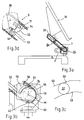
- the web 53 has a shoulder 59, which as The button is used to unlock the lock. To the left of the button 59 shown, the lock 5 is closed, the lock to the right of it is free. 3c is the Lock still closed.
- the fulcrum 56 is arranged that the lever arm between the pivot point 56 and the pin 57 is less than the distance between the control point the control rod 52 with the fulcrum 56.
- the frame arm 30 pivoted up in FIG. 5a then takes the Frame 8 and pivots if necessary in the horizontal Lay back, simply by following the above process steps are processed in reverse order respectively the handlebar is pivoted counterclockwise.
- the device according to the invention also a Fold the frame from the substantially vertical position allowed in the horizontal position, or the device takes the frame from a first machine, then closes the frame transported to another machine and reinserted there.
Landscapes
- Engineering & Computer Science (AREA)
- Mechanical Engineering (AREA)
- Lining Or Joining Of Plastics Or The Like (AREA)
- Harvester Elements (AREA)
- Automatic Cycles, And Cycles In General (AREA)
- Moulds For Moulding Plastics Or The Like (AREA)
- Forklifts And Lifting Vehicles (AREA)
- Apparatuses For Bulk Treatment Of Fruits And Vegetables And Apparatuses For Preparing Feeds (AREA)
- Centrifugal Separators (AREA)
- Diaphragms For Electromechanical Transducers (AREA)
- Processing Of Meat And Fish (AREA)
- Control And Other Processes For Unpacking Of Materials (AREA)
Abstract
Description
- Fig.1
- eine schematische Darstellung in einer Seitenansicht die erfindungsgemäße Rahmenentnahmevorrichtung beziehungsweise die erfindungsgemäße Schweißmaschine.
- Fig.2a
- in einer Seitenansicht die erfindungsmäße Rahmenentnahmevorrichtung,
- Fig. 2b und 2c
- in einer Ansicht Details IIb und IIc in Fig. 2a,
- Fig. 3a
- die erfindungsgemäßte Rahmenentnahmevorrichtung in halb aufgeschwenktem Zustand,
- Fig. 3b und Fig. 3d
- Einzelheiten gemäß IIIb beziehungsweise IIId in Fig. 3a,
- Fig. 3c
- eine Einzelheit der Führungsbahn gemäß Fig. 3b,
- Fig. 4a
- in einer Seitenansicht die Rahmenentnahmevorrichtung 1 in einer weiter geschwenkten Stellung,
- Fig. 4b und 4d
- Einzelheiten gemäß IVb und IVd aus Fig. 4a,
- Fig. 4c
- Einzelheit der Führungsbahn nach IVc in Fig. 4b,
- Fig. 5a
- Endschwenkstellung der erfindungsgemäßen Rahmenentnahmevorrichtung,
- Fig. 5b
- Einzelheit Vb in Fig. 5a.
Claims (21)
- Rahmenentnahmevorrichtung zum Entnehmen eines aus miteinander verbundenen Profilen bestehenden Rahmens aus einer Rahmenbearbeitungs- und/oder Rahmenherstellmaschine, wobei die Vorrichtung ein aus mindestens einem Gestellarm bestehendes, durch einen Antrieb bewegbares, den Rahmen tragendes Gestell aufweist, dadurch gekennzeichnet, daß das Gestell (3) einen Lenker (2) aufweist und der Gestellarm (30) zumindest zeitweise gegenüber dem Lenker (2) verschwenkbar (20) ist.
- Rahmenentnahmevorrichtung nach dem vorhergehenden Anspruch 1, dadurch gekennzeichnet, daß der Rahmen auf dem Gestell (3) aufliegt.
- Rahmenentnahmevorrichtung nach einem oder beiden der vorhergehenden Ansprüche, dadurch gekennzeichnet, daß der Antrieb (4) an dem Lenker (2) angreift und/oder der Antrieb (4) für eine Verschwenkbewegung des Lenkers (2) dient und/oder der Antrieb (4) eine parallelogrammartige Verschiebung des Gestells (3) bewirkt und/oder von dem Antrieb (4) eine Verschwenkbewegung des Gestellarms (30) gegenüber dem Lenker (2) ableitbar ist.
- Rahmenentnahmevorrichtung nach einem oder mehreren der vorhergehenden Ansprüche, dadurch gekennzeichnet, daß an der Vorrichtung (1) zwei Gestellarme (30) mit entweder einem Lenker (2) für beide Gestellarme (30) und/oder je einem eigenen Lenker (2) vorgesehen sind, deren Abstand entsprechend der Rahmenbreite variierbar ist.
- Rahmenentnahmevorrichtung nach einem oder mehreren der vorhergehenden Ansprüche, dadurch gekennzeichnet, daß sich die Gestellarme (30) gleichzeitig, parallel bewegen.
- Rahmenentnahmevorrichtung nach einem oder mehreren der vorhergehenden Ansprüche, dadurch gekennzeichnet, daß das Gestell (3) einen vertikal oder im Wesentlichen vertikal in der Bearbeitungs- oder Rahmenherstellmaschine (9) gelagerten Rahmen (8) aufnimmt.
- Rahmenentnahmevorrichtung nach einem oder mehreren der vorhergehenden Ansprüche, dadurch gekennzeichnet, daß das Gestell (3) den Rahmen (8) aus der Rahmenbearbeitungsoder Rahmenherstellmaschine (9) im Wesentlichen parallel übernimmt und einem nachfolgenden Aggregat in im Wesentlichen gleicher Position übergibt.
- Rahmenentnahmevorrichtung nach einem oder mehreren der vorhergehenden Ansprüche, dadurch gekennzeichnet, daß die Vorrichtung (1) den Rahmen (8) der Rahmenbearbeitungs- oder Rahmenherstellmaschine (9) entnimmt und danach das Gestell so geschwenkt wird, daß der Rahmen horizontal oder im Wesentlichen horizontal orientiert gelagert ist.
- Rahmenentnahmevorrichtung nach einem oder mehreren der vorhergehenden Ansprüche, dadurch gekennzeichnet, daß die Gestellarme (30) Transportmittel, insbesondere Förderbänder für den Rahmen (8) aufweisen.
- Rahmenentnahmevorrichtung nach einem oder mehreren der vorhergehenden Ansprüche, dadurch gekennzeichnet, daß für ein Verschwenken des Gestellarmes (30) gegenüber dem Lenker (2) ein Ketten- oder Seilzug (41) vorgesehen ist, der von dem Verschwenkantrieb (4) angesteuert ist.
- Rahmenentnahmevorrichtung nach einem oder mehreren der vorhergehenden Ansprüche, dadurch gekennzeichnet, daß der Lenker (2) mit dem Gestell (3) arretierbar (5) ist.
- Rahmenentnahmevorrichtung nach einem oder mehreren der vorhergehenden Ansprüche, dadurch gekennzeichnet, daß die Arretierung (5) von der Winkelstellung des Lenkers (2) gegenüber der Horizontalen, oder gegenüber dem Gestellarm (30) abhängt.
- Rahmenentnahmevorrichtung nach einem oder mehreren der vorhergehenden Ansprüche, dadurch gekennzeichnet, daß der Lenker (2) um eine insbesondere horizontal orientierte Drehachse (46) mit Hilfe des Verschwenkantriebes (4) verschwenkbar ist.
- Rahmenentnahmevorrichtung nach einem oder mehreren der vorhergehenden Ansprüche, dadurch gekennzeichnet, daß für die Arretierung (5) mindestens ein durch eine Schubstange oder Steuerstange (52) bewegbarer Arretierhebel (50) vorgesehen ist und die Bewegung des Arretierhebels (50) von dem Verschwenkantrieb (4) ableitbar ist und/oder als Antrieb (4) ein frequenzgesteuerter Elektrogetriebemotor oder ein hydraulischer Drehzylinder oder dergleichen vorgesehen ist.
- Rahmenentnahmevorrichtung nach einem oder mehreren der vorhergehenden Ansprüche, dadurch gekennzeichnet, daß über die Frequenzsteuerung der Elektromotoren die Bewegungen der an der Vorrichtung (1) vorgesehenen Gestellarme (30) synchronisierbar sind.
- Rahmenentnahmevorrichtung nach einem oder mehreren der vorhergehenden Ansprüche, dadurch gekennzeichnet, daß auf der Antriebswelle ein Kettenritzel (45) mit einer Anschlagscheibe (43) vorgesehen ist und über das Kettenritzel (45) die Kette (41) für das Verschwenken des Gestellarmes (30) gegenüber dem Lenker (2) erfolgt.
- Rahmenentnahmevorrichtung nach einem oder mehreren der vorhergehenden Ansprüche, dadurch gekennzeichnet, daß an dem Lenker (2) ein Umlenkhebel (55) mit einem Stift (57) drehbar gelagert ist und der Stift (57) in einer Bahnscheibe (58) geführt ist, der Umlenkhebel (55) auf die Schubstange (52) wirkt und durch eine Veränderung der Bahn (53) der Bahnscheibe (58) die Schubstange (52) bewegbar ist.
- Rahmenentnahmevorrichtung nach einem oder mehreren der vorhergehenden Ansprüche, dadurch gekennzeichnet, daß die Anschlagscheibe (43) dann eine Drehung des Ritzels (45) verhindert, wenn der Gestellarm (30) vom Lenker (2) entriegelt ist.
- Rahmenentnahmevorrichtung nach einem oder mehreren der vorhergehenden Ansprüche, dadurch gekennzeichnet, daß die Bewegung und/oder die Arretierung des Gestellarmes (30) gegenüber dem Lenker (2) mechanisch zwangsgeführt von der Verschwenk-bewegung des Lenkers (2) abgeleitet ist.
- Schweißmaschine zum Schweißen von Kunststoffprofilrahmen, insbesondere Fensterrahmen, mit einer Rahmenentnahmevorrichtung nach einem oder mehreren der vorhergehenden Ansprüche.
- Schweißmaschine nach Anspruch 20, dadurch gekennzeichnet, daß die Rahmenebene (8) in der Schweißmaschine (9) im Wesentlichen vertikal oder mit einem Winkel von bis zu 30° zur Vertikalen hin orientiert ist und/oder die Rahmenentnahmevorrichtung aus der Schweißmaschine geschweißte, noch nicht ausgehärtete Rahmen entnimmt.
Applications Claiming Priority (2)
| Application Number | Priority Date | Filing Date | Title |
|---|---|---|---|
| DE20101639U DE20101639U1 (de) | 2001-01-29 | 2001-01-29 | Vorrichtung zum Entnehmen eines Rahmens aus einer Rahmenbearbeitungs- oder Rahmenherstellungsmaschine |
| DE20101639U | 2001-01-29 |
Publications (3)
| Publication Number | Publication Date |
|---|---|
| EP1226898A2 true EP1226898A2 (de) | 2002-07-31 |
| EP1226898A3 EP1226898A3 (de) | 2003-04-16 |
| EP1226898B1 EP1226898B1 (de) | 2007-02-07 |
Family
ID=7952306
Family Applications (1)
| Application Number | Title | Priority Date | Filing Date |
|---|---|---|---|
| EP02002162A Expired - Lifetime EP1226898B1 (de) | 2001-01-29 | 2002-01-29 | Rahmenentnahmevorrichtung |
Country Status (3)
| Country | Link |
|---|---|
| EP (1) | EP1226898B1 (de) |
| AT (1) | ATE353266T1 (de) |
| DE (2) | DE20101639U1 (de) |
Cited By (1)
| Publication number | Priority date | Publication date | Assignee | Title |
|---|---|---|---|---|
| US7546684B2 (en) | 2004-07-27 | 2009-06-16 | General Electric Company | Method for repair and replacement of combustor liner panel |
Family Cites Families (4)
| Publication number | Priority date | Publication date | Assignee | Title |
|---|---|---|---|---|
| BE648378A (de) * | ||||
| DE3726652A1 (de) * | 1987-08-11 | 1989-02-23 | Urban Maschinenbau | Vorrichtung zum verschweissen von kunststoffprofilen |
| US5249663A (en) * | 1991-10-04 | 1993-10-05 | Carl Strutz And Company, Inc. | Apparatus to load workpieces |
| EP0753378A1 (de) * | 1995-07-13 | 1997-01-15 | ROTOX GmbH B. EISENBACH | Vorrichtung zum Transportieren, Positionieren und/oder Verschwenken eines Rahmens sowie Verfahren hierzu |
-
2001
- 2001-01-29 DE DE20101639U patent/DE20101639U1/de not_active Expired - Lifetime
-
2002
- 2002-01-29 EP EP02002162A patent/EP1226898B1/de not_active Expired - Lifetime
- 2002-01-29 AT AT02002162T patent/ATE353266T1/de not_active IP Right Cessation
- 2002-01-29 DE DE50209419T patent/DE50209419D1/de not_active Expired - Lifetime
Cited By (1)
| Publication number | Priority date | Publication date | Assignee | Title |
|---|---|---|---|---|
| US7546684B2 (en) | 2004-07-27 | 2009-06-16 | General Electric Company | Method for repair and replacement of combustor liner panel |
Also Published As
| Publication number | Publication date |
|---|---|
| DE20101639U1 (de) | 2002-06-06 |
| EP1226898B1 (de) | 2007-02-07 |
| DE50209419D1 (de) | 2007-03-22 |
| EP1226898A3 (de) | 2003-04-16 |
| ATE353266T1 (de) | 2007-02-15 |
Similar Documents
| Publication | Publication Date | Title |
|---|---|---|
| DE3908496C2 (de) | Handhabungsvorrichtung für eine Biegemaschine, Verfahren zur Umkehrung der Lage eines Werkstückes in einem Biegeverfahren und Biegemaschine | |
| DE3312721C2 (de) | Fördereinrichtung zum Überführen von Werkstücken zwischen zwei Pressen einer Pressenstraße | |
| EP1982799A1 (de) | Handhabungsanordnung | |
| EP0536528A1 (de) | Vorrichtung zur Bewegung einer Schwenkschiebetür für Fahrzeuge zur Personenbeförderung, insbesondere Schienenfahrzeuge | |
| DE2713706A1 (de) | Uebergabeeinrichtung, insbesondere fuer pressen | |
| DE3318851C2 (de) | ||
| DE3702108C2 (de) | Motorgetriebene Vorrichtung zum Umsetzen von Werkstücken | |
| DE3607020A1 (de) | Montageeinrichtung fuer karosserieteile von kraftfahrzeugen | |
| DE19500652C1 (de) | Handhabungsvorrichtung für eine Werkzeugmaschine | |
| DE2512613C2 (de) | Sauggreifeinrichtung zum Erfassen und Handhaben eines quaderförmigen Körpers | |
| DE19607837A1 (de) | Vorrichtung zum Dekorieren von einzelnen Objekten | |
| DE2800828A1 (de) | Vorrichtung zum wenden von werkstuecken | |
| DE2147436C3 (de) | Vorrichtung für Maschinen mit relativ zueinander bewegbaren Formhälften, insbesondere Druckgießmaschinen | |
| DE69617485T2 (de) | Mehrstufige Umformmaschine | |
| EP0718223B1 (de) | Umsetzvorrichtung für Güter, insbesondere Dosen | |
| DE2236188C3 (de) | Fördervorrichtung | |
| EP0889467A2 (de) | Verfahren und Vorrichtung zum Dekorieren von flachen selbsttragenden Objekten | |
| EP0157950B1 (de) | Werkzeugmaschine mit einem in mehreren Achsen beweglichen Spindelstock | |
| DE2420240B2 (de) | Vorrichtung zum Transport eines Druckgußstückes aus einer Druckgießmaschine in eine Abgratpresse | |
| EP1226898B1 (de) | Rahmenentnahmevorrichtung | |
| DE3925859C2 (de) | Blasformmaschine | |
| EP0271008B1 (de) | Fördereinrichtung zum Fördern von Kraftfahrzeugkarosserien | |
| DE2428897C3 (de) | Vorrichtung zum Herstellen von keramischen Hohlgefäßen im Gießverfahren | |
| EP0621089B1 (de) | Kanter zum Drehen von Walzgut | |
| DE3828267A1 (de) | Vorrichtung zum zusammenbau von fahrzeugkarosserien wie automobile oder dgl. |
Legal Events
| Date | Code | Title | Description |
|---|---|---|---|
| PUAI | Public reference made under article 153(3) epc to a published international application that has entered the european phase |
Free format text: ORIGINAL CODE: 0009012 |
|
| AK | Designated contracting states |
Kind code of ref document: A2 Designated state(s): AT BE CH CY DE DK ES FI FR GB GR IE IT LI LU MC NL PT SE TR |
|
| AX | Request for extension of the european patent |
Free format text: AL;LT;LV;MK;RO;SI |
|
| PUAL | Search report despatched |
Free format text: ORIGINAL CODE: 0009013 |
|
| AK | Designated contracting states |
Designated state(s): AT BE CH CY DE DK ES FI FR GB GR IE IT LI LU MC NL PT SE TR |
|
| AX | Request for extension of the european patent |
Extension state: AL LT LV MK RO SI |
|
| RIC1 | Information provided on ipc code assigned before grant |
Ipc: 7B 23Q 7/02 B Ipc: 7B 23Q 7/04 B Ipc: 7B 23Q 1/54 A Ipc: 7B 23Q 7/00 B |
|
| 17P | Request for examination filed |
Effective date: 20030614 |
|
| 17Q | First examination report despatched |
Effective date: 20030902 |
|
| AKX | Designation fees paid |
Designated state(s): AT BE DE GB IT |
|
| GRAP | Despatch of communication of intention to grant a patent |
Free format text: ORIGINAL CODE: EPIDOSNIGR1 |
|
| RIN1 | Information on inventor provided before grant (corrected) |
Inventor name: TESCH, WOLFGANG |
|
| GRAS | Grant fee paid |
Free format text: ORIGINAL CODE: EPIDOSNIGR3 |
|
| GRAA | (expected) grant |
Free format text: ORIGINAL CODE: 0009210 |
|
| AK | Designated contracting states |
Kind code of ref document: B1 Designated state(s): AT BE DE GB IT |
|
| REG | Reference to a national code |
Ref country code: GB Ref legal event code: FG4D Free format text: NOT ENGLISH |
|
| REF | Corresponds to: |
Ref document number: 50209419 Country of ref document: DE Date of ref document: 20070322 Kind code of ref document: P |
|
| GBT | Gb: translation of ep patent filed (gb section 77(6)(a)/1977) |
Effective date: 20070301 |
|
| PLBE | No opposition filed within time limit |
Free format text: ORIGINAL CODE: 0009261 |
|
| STAA | Information on the status of an ep patent application or granted ep patent |
Free format text: STATUS: NO OPPOSITION FILED WITHIN TIME LIMIT |
|
| 26N | No opposition filed |
Effective date: 20071108 |
|
| PGFP | Annual fee paid to national office [announced via postgrant information from national office to epo] |
Ref country code: AT Payment date: 20090108 Year of fee payment: 8 |
|
| PGFP | Annual fee paid to national office [announced via postgrant information from national office to epo] |
Ref country code: GB Payment date: 20090123 Year of fee payment: 8 |
|
| PGFP | Annual fee paid to national office [announced via postgrant information from national office to epo] |
Ref country code: BE Payment date: 20090129 Year of fee payment: 8 |
|
| PGFP | Annual fee paid to national office [announced via postgrant information from national office to epo] |
Ref country code: IT Payment date: 20090123 Year of fee payment: 8 |
|
| BERE | Be: lapsed |
Owner name: URBAN G.M.B.H. & CO. MASCHINENBAU KG Effective date: 20100131 |
|
| PGFP | Annual fee paid to national office [announced via postgrant information from national office to epo] |
Ref country code: DE Payment date: 20100324 Year of fee payment: 9 |
|
| GBPC | Gb: european patent ceased through non-payment of renewal fee |
Effective date: 20100129 |
|
| PG25 | Lapsed in a contracting state [announced via postgrant information from national office to epo] |
Ref country code: AT Free format text: LAPSE BECAUSE OF NON-PAYMENT OF DUE FEES Effective date: 20100129 |
|
| PG25 | Lapsed in a contracting state [announced via postgrant information from national office to epo] |
Ref country code: GB Free format text: LAPSE BECAUSE OF NON-PAYMENT OF DUE FEES Effective date: 20100129 |
|
| PG25 | Lapsed in a contracting state [announced via postgrant information from national office to epo] |
Ref country code: BE Free format text: LAPSE BECAUSE OF NON-PAYMENT OF DUE FEES Effective date: 20100131 |
|
| PG25 | Lapsed in a contracting state [announced via postgrant information from national office to epo] |
Ref country code: IT Free format text: LAPSE BECAUSE OF NON-PAYMENT OF DUE FEES Effective date: 20100129 |
|
| REG | Reference to a national code |
Ref country code: DE Ref legal event code: R119 Ref document number: 50209419 Country of ref document: DE Effective date: 20110802 |
|
| PG25 | Lapsed in a contracting state [announced via postgrant information from national office to epo] |
Ref country code: DE Free format text: LAPSE BECAUSE OF NON-PAYMENT OF DUE FEES Effective date: 20110802 |