EP1226902A2 - Twin lobe impact mechanism - Google Patents
Twin lobe impact mechanism Download PDFInfo
- Publication number
- EP1226902A2 EP1226902A2 EP02004848A EP02004848A EP1226902A2 EP 1226902 A2 EP1226902 A2 EP 1226902A2 EP 02004848 A EP02004848 A EP 02004848A EP 02004848 A EP02004848 A EP 02004848A EP 1226902 A2 EP1226902 A2 EP 1226902A2
- Authority
- EP
- European Patent Office
- Prior art keywords
- anvil
- impact
- dog hammer
- lobes
- hammer
- Prior art date
- Legal status (The legal status is an assumption and is not a legal conclusion. Google has not performed a legal analysis and makes no representation as to the accuracy of the status listed.)
- Withdrawn
Links
Images


Classifications
-
- B—PERFORMING OPERATIONS; TRANSPORTING
- B25—HAND TOOLS; PORTABLE POWER-DRIVEN TOOLS; MANIPULATORS
- B25B—TOOLS OR BENCH DEVICES NOT OTHERWISE PROVIDED FOR, FOR FASTENING, CONNECTING, DISENGAGING, OR HOLDING
- B25B21/00—Portable power-driven screw or nut setting or loosening tools; Attachments for drilling apparatus serving the same purpose
- B25B21/02—Portable power-driven screw or nut setting or loosening tools; Attachments for drilling apparatus serving the same purpose with means for imparting impact to screwdriver blade or nut socket
- B25B21/026—Impact clutches
-
- B—PERFORMING OPERATIONS; TRANSPORTING
- B25—HAND TOOLS; PORTABLE POWER-DRIVEN TOOLS; MANIPULATORS
- B25B—TOOLS OR BENCH DEVICES NOT OTHERWISE PROVIDED FOR, FOR FASTENING, CONNECTING, DISENGAGING, OR HOLDING
- B25B21/00—Portable power-driven screw or nut setting or loosening tools; Attachments for drilling apparatus serving the same purpose
- B25B21/02—Portable power-driven screw or nut setting or loosening tools; Attachments for drilling apparatus serving the same purpose with means for imparting impact to screwdriver blade or nut socket
Definitions
- the present invention relates generally to impact tools. More particularly, the invention relates to an impact tool with a twin lobed anvil, and the separate anvil, timing shaft and mating dog hammer. In combination, the components provide a harder blow to the anvil of an impact tool due to a larger strike surface area, provide greater torque due to increased mass at engagement, and increase the durability of the impact tool.
- US-A-3 428 137 discloses an impact tool comprising: an anvil having two lobes extending therefrom; a timing shaft operatively coupled to the anvil; a dog hammer having a surface shaped to conform to the lobes of the anvil, wherein an impact of the dog hammer on the anvil takes place at the lobes; and a pneumatic motor (100, 106, 108) rotatably connected to the timing shaft and the dog hammer.
- an impact tool of the general type disclosed in the prior art is characterised in that the lobes of the anvil are substantially in the shape of an ellipse with a tumescent centre, and the dog hammer further includes a ring guidance surface which continuously encircles outer ends of the lobes of the anvil.
- the impact transmission component parts thereof increase the strength of the transmission and reduce the impact transmitted to a user.
- the dog hammer preferably includes an anvil-receiving portion having a first tier and second tier and a ring guidance portion that encircles the outer periphery of the projections of the anvil.
- the first tier of the dog hammer preferably includes a portion that supports the lobes during non-impacting transmission and the second tier may be shaped to receive the two lobes of the anvil during an impacting transmission.
- the apparatus also includes a timing shaft to time the impact transmission occurrences.
- the anvil in accordance with the present invention preferably includes a substantially circular plated portion surrounding the bore of the anvil at a rear end of the anvil.
- the dog hammer of the tool in accordance with a preferred embodiment of invention includes a recessed first tier for supporting an impact portion of an anvil during a non-impact timing, and a further recessed second tier for impacting an impact portion of an anvil during an impact timing.
- the timing shaft may include an anvil rotation transmission portion, a ball timing portion with a groove to rotatably support a ball, and a rotor connection portion.
- FIG. 1 a cross-sectional view of an impact tool 10 in accordance with the present invention is disclosed.
- the impact tool 10 generally includes a handle 12 connected to the rear of a motor housing 8 which is in turn connected to an impact transmission section housing 6.
- the handle 12 can be of any conventional configuration to selectively supply pressurized fluid to the motor housing 8 and, accordingly, will not be described in detail herein.
- the motor housing 8 generally includes a rotor 100 including rotor blades 106 which are turned by the flow of pressurized fluid (e.g., pneumatically driven) through the motor housing 8 as is conventional.
- the rotor housing has a front end defined by plate 104 that holds the rotor in the motor housing 8.
- the rotor also includes a rotor output shaft 108 that extends through the plate 104 and is rotatably connected to the impact transmission to be described in detail hereafter.
- the rotor output shaft 108 is supported by a bearing 16 within the motor housing 8.
- the impact transmission of the present invention generally includes an anvil 20, a timing shaft 40 and a dog hammer 60.
- the impact transmission being rotatably coupled to the rotor output shaft 108 by a coupling 98 which includes interior and exterior 92 splines.
- the interior splines mating with exterior splines of the rotor output shaft 108.
- the exterior splines 92 mating with interior splines 62 located on a rear interior of the dog hammer 60.
- the anvil 20 includes a generally cylindrical body 34 including a bore 26 extending partially therein.
- the bore 26 includes a groove or keyway 28 to receive a key 90 that mates with a groove or keyway in the timing shaft 40.
- an output shaft 30 is provided which can receive a variety of tools (not shown).
- the rear end of the anvil includes a substantially circular plate portion 32 that extends radially from an outer surface of the cylindrical portion 34.
- the anvil On the circular plate 32, the anvil includes at least two rearwardly projecting projections or lobes 22 which receive the impact transmission from the dog hammer 60. As shown in Fig. 3, the lobes 22 and area which connects the lobes to one another is generally in an elliptical shape with a swelled or tumescent center 24.
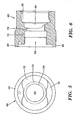
- the dog hammer 60 is generally a cylindrical member have a series of differently sized bores extending therethrough.
- the dog hammer includes a circular guidance surface 66 which encircles the circular plate 32 of the anvil to assure proper alignment of the anvil 20 and dog hammer 60.
- the dog hammer Inwardly of the guidance surface 66, the dog hammer includes tiered anvil mating recesses 70 and 72.
- the first tiered recess 70 engages the lobes 22 of the anvil 20 during a non-impacting timing of operation.
- a further recessed, second tier 72 engages the lobes 22 during impact timing to transmit the impact from the dog hammer 60 to the anvil 20.
- the second tier 72 as shown in Fig. 5, is generally in a shape that mates with the elliptical shape with tumescent center shape of the lobes 22. In other words, the second tier is generally hourglass shaped as can be seen from Fig. 5.
- the dog hammer 60 includes a throughbore 76 which is sized to accommodate the passage of the timing shaft 40 therethrough.
- the bore 74 that extends from the second tier 72 to the throughbore 76 serves a double purpose, that of a spring 80 engaging groove.
- Adjacent the throughbore 76, the dog hammer includes a ball engaging track 68 which, as the track progresses around the interior of the dog hammer 60, progresses to a peak (not shown), to drive the dog hammer into impact engagement with the anvil 20.
- the ball 95 as shown in Fig. 1, being located between the dog hammer 60 and timing shaft 40.
- the dog hammer Adjacent to the ball engaging track 68, the dog hammer includes a splined bore 62 which, as noted earlier mates with the exterior splines of coupling 98 to receive rotational transmission from the rotor 100.
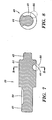
- the timing shaft generally includes a shaft of three different diameters.
- a first portion 46 is sized to be accommodated in the bore 26 of the anvil and includes a groove 50 to receive a pin 90.
- the pin 90 assures rotation of the timing shaft 40 and anvil 20 together.
- a second intermediate portion 44 of the timing shaft is sized to be accommodated in the throughbore 76 of the dog hammer 60.
- the second intermediate portion 44 also including a ball engaging track 48 to accommodate rotation of the ball 95.
- the ball engaging track 48 of the timing shaft extends around approximately 270° of the timing shaft diameter.
- the timing shaft includes a third rotor output shaft 108 engaging portion 42. As shown in Fig. 1, this portion is received on an internal bore of the rotor output shaft 108 for non-power transmitting support. A rear portion of the second intermediate portion 44 is also rotatably supported in the coupling 98.
- the impact transmission is housed within the housing, as shown in Fig. 1.
- the anvil 20 is rotatably mounted in the front portion of the housing 6 via a seal 4 and bushing 2.
- the timing shaft first portion 46 extends into the anvil bore 24 and is rotatably connected to the anvil via pin 90.
- the circular plate 32 of the anvil rests in the guidance surface 66 of the dog hammer 60 so that the anvil 20 is always in some minimal engagement with the dog hammer 60.
- the outer surfaces of the lobes 22 are always within the guidance surface 66.
- the lobes 22 rests against the first tier recess 70 of the dog hammer 60.
- the ball 95 follows the ball engaging track 68 of the dog hammer and passes over the peak within the track.
- the positioning of the peak is set such that the time the ball passes over the peak coincides with the time the lobes 22 of the anvil are in position to enter the second tier recess 72 of the dog hammer.
- the dog hammer impacts the lobes 22 of the anvil with the second tiered recess 72 to transmit an impact.
- excess energy stored in the dog hammer is not allowed to recoil the dog hammer into the housings 6, 8, thus transmitting the impact to the user.
- the tool exhibits increased durability because of removal of the jolting non-contact to immediate contact of the related art.
- the maintenance of contact between the anvil 20 and dog hammer 60 allows for a less jolting impact transmission engagement and, thus, creates a stronger transmission which is also more durable.
- the capability of the present invention to maintain the velocity of the dog hammer as slow as possible so less excess energy is stored in it by increasing the number of degrees necessary to accelerate the dog hammer. Additionally, the time that the dog hammer clears the anvil is set such that the dog hammer is moving the fastest at that point but also such that the average velocity is as low as possible.
Landscapes
- Engineering & Computer Science (AREA)
- Mechanical Engineering (AREA)
- Percussive Tools And Related Accessories (AREA)
- Drilling And Boring (AREA)
Abstract
Description
Timing of the impacts is determined by the structural relationship of the
Claims (7)
- An anvil for use in an impact tool, the anvil comprising:a substantially cylindrical body having a bore therein;a substantially circular plate portion surrounding the bore at a rear end of the anvil; andat least two lobes extending from the plate adapted to receive an impact.
- An anvil according to Claim 1, wherein at least two lobes are substantially in the shape of an ellipse.
- An anvil according to Claim 1 or 2, wherein at least two lobes are substantially in the shape of an ellipse with a tumescent centre.
- An anvil according to Claim 1, 2 or 3, where the bore further includes a keyway.
- An anvil according to any of the preceding claims, wherein the substantially circular plate portion extends radially from the outer surface of the substantially cylindrical body.
- An anvil according to any of the preceding claims, further including an output shaft.
- An anvil according to any of the preceding claims, wherein at least
two lobes are rearwardly projecting.
Applications Claiming Priority (3)
| Application Number | Priority Date | Filing Date | Title |
|---|---|---|---|
| US902385 | 1997-07-29 | ||
| US08/902,385 US6003618A (en) | 1997-07-29 | 1997-07-29 | Twin lobe impact mechanism |
| EP98306004A EP0894576A3 (en) | 1997-07-29 | 1998-07-28 | Twin lobe impact mechanism |
Related Parent Applications (1)
| Application Number | Title | Priority Date | Filing Date |
|---|---|---|---|
| EP98306004A Division EP0894576A3 (en) | 1997-07-29 | 1998-07-28 | Twin lobe impact mechanism |
Publications (2)
| Publication Number | Publication Date |
|---|---|
| EP1226902A2 true EP1226902A2 (en) | 2002-07-31 |
| EP1226902A3 EP1226902A3 (en) | 2002-11-27 |
Family
ID=25415792
Family Applications (3)
| Application Number | Title | Priority Date | Filing Date |
|---|---|---|---|
| EP02004848A Withdrawn EP1226902A3 (en) | 1997-07-29 | 1998-07-28 | Twin lobe impact mechanism |
| EP98306004A Withdrawn EP0894576A3 (en) | 1997-07-29 | 1998-07-28 | Twin lobe impact mechanism |
| EP02004849A Withdrawn EP1240979A3 (en) | 1997-07-29 | 1998-07-28 | Twin lobe impact mechanism |
Family Applications After (2)
| Application Number | Title | Priority Date | Filing Date |
|---|---|---|---|
| EP98306004A Withdrawn EP0894576A3 (en) | 1997-07-29 | 1998-07-28 | Twin lobe impact mechanism |
| EP02004849A Withdrawn EP1240979A3 (en) | 1997-07-29 | 1998-07-28 | Twin lobe impact mechanism |
Country Status (8)
| Country | Link |
|---|---|
| US (2) | US6003618A (en) |
| EP (3) | EP1226902A3 (en) |
| JP (1) | JPH1190860A (en) |
| KR (1) | KR19990014258A (en) |
| BR (1) | BR9802612A (en) |
| CA (1) | CA2242446A1 (en) |
| TW (1) | TW396093B (en) |
| ZA (1) | ZA986263B (en) |
Families Citing this family (27)
| Publication number | Priority date | Publication date | Assignee | Title |
|---|---|---|---|---|
| DE19833943C2 (en) * | 1998-07-28 | 2000-07-13 | Rodcraft Pneumatic Tools Gmbh | Impact wrench |
| US6491111B1 (en) | 2000-07-17 | 2002-12-10 | Ingersoll-Rand Company | Rotary impact tool having a twin hammer mechanism |
| US20040206523A1 (en) * | 2002-08-06 | 2004-10-21 | Giardino David A. | Control device for a power impact tool |
| US6823949B2 (en) | 2002-08-06 | 2004-11-30 | Chicago Pneumatic Tool Company | Modular control apparatus for a power impact tool |
| US6863134B2 (en) * | 2003-03-07 | 2005-03-08 | Ingersoll-Rand Company | Rotary tool |
| US7052022B2 (en) * | 2003-05-13 | 2006-05-30 | Snap-On Incorporated | Chuck for pneumatic hammer |
| US20060225903A1 (en) * | 2005-04-07 | 2006-10-12 | Sterling Robert E | Rotary impact tool, shock attenuating coupling device for a rotary impact tool, and rotary impact attenuating device |
| US20060237205A1 (en) * | 2005-04-21 | 2006-10-26 | Eastway Fair Company Limited | Mode selector mechanism for an impact driver |
| JP4701084B2 (en) * | 2005-12-27 | 2011-06-15 | 日本ニューマチック工業株式会社 | Air hammer |
| TWI424910B (en) * | 2006-01-27 | 2014-02-01 | Exhaust Technologies Inc | Shock attenuating device for a rotary impact tool |
| US7438140B2 (en) * | 2006-01-27 | 2008-10-21 | Exhaust Technologies, Inc. | Shock attenuating device for a rotary impact tool |
| TWM308153U (en) * | 2006-08-24 | 2007-03-21 | Mobiletron Electronics Co Ltd | Punching spindle of electric tool |
| US20110139474A1 (en) * | 2008-05-05 | 2011-06-16 | Warren Andrew Seith | Pneumatic impact tool |
| CN102083593B (en) * | 2008-05-07 | 2014-07-23 | 密尔沃基电动工具公司 | Drive assembly for a power tool |
| US8020630B2 (en) * | 2009-05-29 | 2011-09-20 | Ingersoll Rand Company | Swinging weight assembly for impact tool |
| US9289886B2 (en) | 2010-11-04 | 2016-03-22 | Milwaukee Electric Tool Corporation | Impact tool with adjustable clutch |
| US9592600B2 (en) | 2011-02-23 | 2017-03-14 | Ingersoll-Rand Company | Angle impact tools |
| US8925646B2 (en) | 2011-02-23 | 2015-01-06 | Ingersoll-Rand Company | Right angle impact tool |
| SE535919C2 (en) * | 2011-06-30 | 2013-02-19 | Atlas Copco Ind Tech Ab | Electrically powered tool |
| US9022888B2 (en) | 2013-03-12 | 2015-05-05 | Ingersoll-Rand Company | Angle impact tool |
| US9555532B2 (en) | 2013-07-01 | 2017-01-31 | Ingersoll-Rand Company | Rotary impact tool |
| US9539715B2 (en) | 2014-01-16 | 2017-01-10 | Ingersoll-Rand Company | Controlled pivot impact tools |
| JP6952241B2 (en) * | 2017-08-29 | 2021-10-20 | パナソニックIpマネジメント株式会社 | Electric tool |
| CA3037784A1 (en) * | 2018-09-06 | 2020-03-06 | Tti (Macao Commercial Offshore) Limited | Rotary impact tools with noise reduction mechanism |
| WO2022094788A1 (en) * | 2020-11-04 | 2022-05-12 | Jacobs Chuck Manufacturing (Suzhou) Company, Ltd. | Impact driver anvil |
| US12048988B2 (en) * | 2020-12-08 | 2024-07-30 | Snap-On Incorporated | Impact mechanism for a rotary impact tool |
| JP2023181600A (en) * | 2022-06-13 | 2023-12-25 | 株式会社マキタ | impact tools |
Family Cites Families (29)
| Publication number | Priority date | Publication date | Assignee | Title |
|---|---|---|---|---|
| US2733621A (en) * | 1956-02-07 | John p | ||
| DE116436C (en) * | ||||
| US2514914A (en) * | 1945-08-06 | 1950-07-11 | Reed Roller Bit Co | Impact wrench |
| US2691434A (en) * | 1949-10-11 | 1954-10-12 | Ingersoll Rand Co | Biasing mechanism for impact wrenches |
| US2850128A (en) * | 1952-08-01 | 1958-09-02 | Rotor Tool Company | Rotary impact clutch |
| US2881884A (en) * | 1955-01-12 | 1959-04-14 | Chicago Pneumatic Tool Co | Impact clutch |
| US2947283A (en) * | 1955-02-04 | 1960-08-02 | Earl G Roggenburk | Impact tool |
| US2863539A (en) * | 1956-12-10 | 1958-12-09 | Herrick L Johnston Inc | Impact mechanism |
| US3174597A (en) * | 1961-12-19 | 1965-03-23 | Chicago Pneumatic Tool Co | Impact clutch |
| DE1478807A1 (en) * | 1962-07-03 | 1969-03-13 | Bosch Gmbh Robert | Motor-driven rotary impact device |
| US3237703A (en) * | 1964-04-07 | 1966-03-01 | Ingersoll Rand Co | Rotary impact tool |
| US3389756A (en) * | 1965-08-09 | 1968-06-25 | Kawamoto Mitsugi | Impact wrench |
| US3414065A (en) * | 1967-04-26 | 1968-12-03 | Rockwell Mfg Co | Rotary impact tool |
| US3428137A (en) * | 1967-10-12 | 1969-02-18 | Chicago Pneumatic Tool Co | Impact wrench |
| SE320334B (en) * | 1968-09-24 | 1970-02-02 | Atlas Copco Ab | |
| BE754703A (en) * | 1969-06-18 | 1971-01-18 | Dresser Ind | PERCUSSION TOOL |
| DE2047442A1 (en) * | 1970-09-26 | 1972-03-30 | Otto Baier Kg Maschinenfabrik, 7140 Ludwigsburg | drilling machine |
| US3730281A (en) * | 1971-06-07 | 1973-05-01 | Black & Decker Mfg Co | Drill hammer-drill mechanism for power tool |
| DE2364344A1 (en) * | 1973-12-22 | 1975-06-26 | Impex Essen Vertrieb | Jackhammer with striker hammer damping system - compression chamber and choke outlet controlled by hammer tip piston |
| SE391143B (en) * | 1974-10-02 | 1977-02-07 | Atlas Copco Ab | ROTATION BATCH COUPLING |
| US4350213A (en) * | 1979-10-19 | 1982-09-21 | Antipov Georgy A | Impact wrench |
| US4347902A (en) * | 1979-12-18 | 1982-09-07 | Chicago Pneumatic Tool Company | Rotary impact wrench clutch |
| JPS6033628B2 (en) * | 1981-01-27 | 1985-08-03 | 株式会社 空研 | Impact rotation device in impact wrench |
| DE3239283A1 (en) * | 1981-11-13 | 1983-05-19 | Black & Decker, Inc., 19711 Newark, Del. | MOTOR DRIVEN TOOL, ESPECIALLY ELECTRIC TOOL WITH A PLASTIC HOUSING |
| EP0149874B1 (en) * | 1984-01-05 | 1988-03-23 | Kabushiki Kaisha Kuken | An impact wrench |
| US4712456A (en) * | 1986-07-02 | 1987-12-15 | Top Driver Enterprise Co., Ltd. | Electric torsion-controlled screwdriver with an improved automatic turn-off device |
| US5083619A (en) * | 1989-09-25 | 1992-01-28 | Chicago Pneumatic Tool Company | Powered impact wrench |
| JP3071523B2 (en) * | 1991-10-08 | 2000-07-31 | 株式会社マキタ | Detent device in screw driver |
| JP2558753Y2 (en) * | 1991-10-31 | 1998-01-14 | 株式会社マキタ | Power transmission mechanism for rotary electric tools |
-
1997
- 1997-07-29 US US08/902,385 patent/US6003618A/en not_active Expired - Fee Related
-
1998
- 1998-07-07 CA CA002242446A patent/CA2242446A1/en not_active Abandoned
- 1998-07-15 ZA ZA9806263A patent/ZA986263B/en unknown
- 1998-07-15 TW TW087111497A patent/TW396093B/en not_active IP Right Cessation
- 1998-07-28 EP EP02004848A patent/EP1226902A3/en not_active Withdrawn
- 1998-07-28 BR BR9802612-7A patent/BR9802612A/en not_active Application Discontinuation
- 1998-07-28 EP EP98306004A patent/EP0894576A3/en not_active Withdrawn
- 1998-07-28 EP EP02004849A patent/EP1240979A3/en not_active Withdrawn
- 1998-07-29 JP JP10213905A patent/JPH1190860A/en active Pending
- 1998-07-29 KR KR1019980030499A patent/KR19990014258A/en not_active Withdrawn
- 1998-10-01 US US09/164,561 patent/US6047779A/en not_active Expired - Fee Related
Also Published As
| Publication number | Publication date |
|---|---|
| US6003618A (en) | 1999-12-21 |
| JPH1190860A (en) | 1999-04-06 |
| US6047779A (en) | 2000-04-11 |
| EP1240979A3 (en) | 2002-11-27 |
| KR19990014258A (en) | 1999-02-25 |
| CA2242446A1 (en) | 1999-01-29 |
| EP0894576A3 (en) | 2000-03-29 |
| EP1226902A3 (en) | 2002-11-27 |
| EP1240979A2 (en) | 2002-09-18 |
| ZA986263B (en) | 1999-08-30 |
| TW396093B (en) | 2000-07-01 |
| BR9802612A (en) | 1999-10-05 |
| EP0894576A2 (en) | 1999-02-03 |
Similar Documents
| Publication | Publication Date | Title |
|---|---|---|
| US6003618A (en) | Twin lobe impact mechanism | |
| US6223834B1 (en) | Impact structure for impact power tool | |
| US7048075B2 (en) | Power tool | |
| US5337835A (en) | Drill and/or impact hammer | |
| US5588496A (en) | Slip clutch arrangement for power tool | |
| US5906244A (en) | Rotary impact tool with involute profile hammer | |
| EP1371458B1 (en) | Rotary hammer with overload clutch | |
| US6923271B2 (en) | Hand power tool | |
| US3605914A (en) | Rotary impact wrench mechanism | |
| US6978847B2 (en) | Hammer | |
| US5740892A (en) | Power wrench torque transmission mechanism | |
| WO1991003655A1 (en) | Universal joint with rotating holder sleeve | |
| US3848680A (en) | Impact clutch mechanism | |
| JP3574240B2 (en) | Hammer drill | |
| US20060225903A1 (en) | Rotary impact tool, shock attenuating coupling device for a rotary impact tool, and rotary impact attenuating device | |
| US4811797A (en) | Impact wrench | |
| JP2001501877A (en) | Impact tool driver | |
| JP3369844B2 (en) | Rotary impact tool with idle hit prevention mechanism | |
| CN120696966A (en) | Hand tools | |
| JPH02284881A (en) | Hammer drill | |
| GB2321089A (en) | Hand machine tool with torque responsive safety clutch | |
| CN1206647A (en) | Twin lobe impact mechanism | |
| JP4405378B2 (en) | Electric tool | |
| JP3238639B2 (en) | Silent clutch for electric screwdriver | |
| EP4234171A1 (en) | Power tool with hammer mechanism |
Legal Events
| Date | Code | Title | Description |
|---|---|---|---|
| PUAI | Public reference made under article 153(3) epc to a published international application that has entered the european phase |
Free format text: ORIGINAL CODE: 0009012 |
|
| 17P | Request for examination filed |
Effective date: 20020322 |
|
| AC | Divisional application: reference to earlier application |
Ref document number: 894576 Country of ref document: EP |
|
| AK | Designated contracting states |
Kind code of ref document: A2 Designated state(s): BE DE ES FR GB IT NL SE |
|
| PUAL | Search report despatched |
Free format text: ORIGINAL CODE: 0009013 |
|
| AK | Designated contracting states |
Kind code of ref document: A3 Designated state(s): BE DE ES FR GB IT NL SE |
|
| STAA | Information on the status of an ep patent application or granted ep patent |
Free format text: STATUS: THE APPLICATION IS DEEMED TO BE WITHDRAWN |
|
| AKX | Designation fees paid |
Designated state(s): BE DE ES FR GB IT NL SE |
|
| 18D | Application deemed to be withdrawn |
Effective date: 20030201 |