EP1227280A2 - Bodenelement zum Erstellen von Hohlraumböden für Heizrohre einer Raumheizung sowie für Heiz- und Kühlrohre einer kombinierten Raumheizung und Raumkühlung für Gebäude - Google Patents
Bodenelement zum Erstellen von Hohlraumböden für Heizrohre einer Raumheizung sowie für Heiz- und Kühlrohre einer kombinierten Raumheizung und Raumkühlung für Gebäude Download PDFInfo
- Publication number
- EP1227280A2 EP1227280A2 EP02000756A EP02000756A EP1227280A2 EP 1227280 A2 EP1227280 A2 EP 1227280A2 EP 02000756 A EP02000756 A EP 02000756A EP 02000756 A EP02000756 A EP 02000756A EP 1227280 A2 EP1227280 A2 EP 1227280A2
- Authority
- EP
- European Patent Office
- Prior art keywords
- floor
- plate
- heating
- elements
- cooling
- Prior art date
- Legal status (The legal status is an assumption and is not a legal conclusion. Google has not performed a legal analysis and makes no representation as to the accuracy of the status listed.)
- Granted
Links
Images

Classifications
-
- F—MECHANICAL ENGINEERING; LIGHTING; HEATING; WEAPONS; BLASTING
- F24—HEATING; RANGES; VENTILATING
- F24D—DOMESTIC- OR SPACE-HEATING SYSTEMS, e.g. CENTRAL HEATING SYSTEMS; DOMESTIC HOT-WATER SUPPLY SYSTEMS; ELEMENTS OR COMPONENTS THEREFOR
- F24D3/00—Hot-water central heating systems
- F24D3/12—Tube and panel arrangements for ceiling, wall, or underfloor heating
- F24D3/14—Tube and panel arrangements for ceiling, wall, or underfloor heating incorporated in a ceiling, wall or floor
- F24D3/141—Tube mountings specially adapted therefor
- F24D3/142—Tube mountings specially adapted therefor integrated in prefab construction elements
-
- F—MECHANICAL ENGINEERING; LIGHTING; HEATING; WEAPONS; BLASTING
- F24—HEATING; RANGES; VENTILATING
- F24D—DOMESTIC- OR SPACE-HEATING SYSTEMS, e.g. CENTRAL HEATING SYSTEMS; DOMESTIC HOT-WATER SUPPLY SYSTEMS; ELEMENTS OR COMPONENTS THEREFOR
- F24D5/00—Hot-air central heating systems; Exhaust gas central heating systems
- F24D5/06—Hot-air central heating systems; Exhaust gas central heating systems operating without discharge of hot air into the space or area to be heated
- F24D5/10—Hot-air central heating systems; Exhaust gas central heating systems operating without discharge of hot air into the space or area to be heated with hot air led through heat-exchange ducts in the walls, floor or ceiling
-
- Y—GENERAL TAGGING OF NEW TECHNOLOGICAL DEVELOPMENTS; GENERAL TAGGING OF CROSS-SECTIONAL TECHNOLOGIES SPANNING OVER SEVERAL SECTIONS OF THE IPC; TECHNICAL SUBJECTS COVERED BY FORMER USPC CROSS-REFERENCE ART COLLECTIONS [XRACs] AND DIGESTS
- Y02—TECHNOLOGIES OR APPLICATIONS FOR MITIGATION OR ADAPTATION AGAINST CLIMATE CHANGE
- Y02B—CLIMATE CHANGE MITIGATION TECHNOLOGIES RELATED TO BUILDINGS, e.g. HOUSING, HOUSE APPLIANCES OR RELATED END-USER APPLICATIONS
- Y02B30/00—Energy efficient heating, ventilation or air conditioning [HVAC]
Definitions
- the invention relates to a floor element for creating Raised floors for heating pipes for space heating as well as for heating and Cooling pipes of a combined room heating and cooling for Building that as a plastic sheet with deep-drawn Holding elements on the top of the board for laying the Pipe coils that can be operated as heating or cooling circuits Pipe circuits of a room heating or a combined Space heating and cooling and deep-drawn support and Spacers on the underside of the plate to support the Slab on a building floor and to form a cavity is formed through which a fresh air and / or circulating air flow for heating or cooling by the underfloor heating or Floor cooling is passed into a building room.
- the known floor heating systems have the disadvantage that they have a certain inertia in their controllability. Therefore are common to maintain the desired room temperatures additional thermostatically controllable direct heating installed.
- the heating power installed in the floor then serves only to cover the basic heating requirement.
- the installation an additional direct heating is very expensive connected, especially since this in the case of a Liquid heating usually with water at a higher temperature than the underfloor heating must be operated.
- a disadvantage also in underfloor heating in the area of windows and Doors a so-called cold air curtain. It also follows disadvantageous an uneven heat distribution on the Floor surface. The temperature reaches the Places where a heating element is located in the floor a maximum and it falls in the range between two Heating elements to a minimum.
- a major disadvantage of the well-known combined Space heating and cooling is that when laying the Floor elements on a raw concrete floor or one on one Impact sound insulation impurities applied to the raw concrete floor remain in the cavity floor, which during operation of the combined space heating and cooling over a long period of time the hot or cold air flow directed through the cavity floor get into the building as dust particles, one Pollution of the rooms and in the worst case can even cause health damage to people, who stay longer in the building rooms.
- the invention has for its object the construction of the generic floor element for creating Raised floors for heating pipes for space heating as well as for heating and Cooling pipes of a combined room heating and cooling for Improve the building so that when the Floor element the penetration of building dirt into the cavity floor is avoided.
- the construction of the floor element according to the invention the a top plate with holding elements on the top of the plate Laying pipe coils and support and spacer elements on the plate underside and one with the support and Spacer elements of the top plate welded bottom plate Formation of a flow-through space or flow-through channel for uses an air flow to be introduced into a building room, the one flowing through the cavity from the Cavity floor created by the heating or Cooling pipes of the cavity floor is heated or cooled, ensures the installation of cavity floors, their Air passage space regardless of the state of the Subfloor is protected against the ingress of building dirt.
- FIG. 1 The schematic representation of Figure 1 shows one with a Combined space heating and cooling 1 equipped Building room 2. There are one on the raw concrete floor 4 of the floor 3 Impact sound and thermal insulation 5 and pressure plates 6 applied, on which floor elements 8 of a cavity floor 7 to accommodate the coils 9 of if necessary as a heating or Cooling circuits operable pipe circuits of a combined Space heating and cooling are installed.
- the heating or cooling circuits are set according to the desired room temperature and depending on the respective outside temperature via pipe distributor 10 by controller 11 connected to a hot and / or cooling water system.
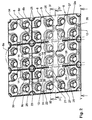
- the floor elements 8 shown in FIGS. 2 to 5 have a top plate 12 made of plastic with deep-drawn Fixing crosses 13 on the plate top 12a for the Pipe coils 9 and deep-drawn support and distance cams 14 on the underside of the plate 12b.
- the support and distance cams 14 of the top plate 12 of the bottom elements 8 are with one on the Raw concrete floor 4 or the impact sound and thermal insulation 5 des
- Floor 3 placeable plastic base plate 15 into one at its four edges 8a - 8d open, rectangular Cavity element with a through-flow space 16 for fresh air and / or circulating air welded by the warm or Pipes 9 flowing through cold water are heated or cooled and which is preferred by one or more in the range of Windows 17 in the floor 3 recessed air outlet boxes 18th is blown into the building room 2.
- the exhaust air is over one or more air outlet openings 19 in the ceiling area and exhaust air lines 20 are sucked out of the building space 2 (FIG. 1).
- the room air is further heated or cooled by the of the heating or cooling pipe coils 9 of the Cavity floor 7 delivered over the surface of the floor 3 Warmth or cold.
- the top plate 12 has at the four edges 8a - 8d of the Cavity element formed bottom element 8 from the Underside of the plate 12b, with the lower plate 15 connected knob segments 25, which act as connecting elements serve for two or four adjacent floor elements 8.
- the support and spacer knobs 14 and the knob segments 25 the top plate 12 of the bottom elements 8 are at Vacuum deep drawing welded to the lower plate 15.
- top plate 12 and the bottom plate 15 of the Floor elements 8 are congruent in a grid Cutting grooves 26 for cutting different ones Floor element formats molded in.
- Connection plates serve to connect the base elements 8 27 with four molded on the underside 27a thereof, in the grid of Support and spacing cams 14 of the floor elements 8 arranged, hollow connecting pin 28 with one of the shape of the cams 14 of the Floor elements 8 adapted shape and another centrally between the four connecting pins 28 on the underside of the plate 27a molded, hollow fixing pin 29 with a shape that the Shape of the connecting knobs 30 is adapted by the Knob segments 25 on the four edges 8a-8d of two or four adjacent floor elements 8 are formed.
- a pin or Nail 31 for fastening the connecting plate 27 with two or four floor elements 8 held together by these on one Floor 3 arranged, or it is a separate pin or Nail used to attach the connecting plate 29.
- the connecting plate 27 engages with two Connecting pin 28 in two support and distance cams 14 two adjacent floor elements 8 and with the fixing pin 29 into one formed by the two floor elements 8 Connection knobs 30 on.
- connection plate 27, each with a connecting pin 28 in one support and distance cam 14 each of the four floor elements 8 and with the fixing pin 29 in one of the four Base elements 8 formed connecting knobs 30.
- a Building space is the fastening pin or nail 31 of the Fixing pin 29 of the connecting plate 27 through a hole 32 in Reason 33 of a connecting knob 30 of two or four adjacent floor elements 8 in the floor 3 and / or one impact sound insulation 5 laid on this.
- the butt joint 34 between two adjacent floor elements 8 is sealed with an adhesive tape 35.
Landscapes
- Engineering & Computer Science (AREA)
- Physics & Mathematics (AREA)
- Thermal Sciences (AREA)
- Chemical & Material Sciences (AREA)
- Combustion & Propulsion (AREA)
- Mechanical Engineering (AREA)
- General Engineering & Computer Science (AREA)
- Floor Finish (AREA)
- Steam Or Hot-Water Central Heating Systems (AREA)
Abstract
Description
- Fig.1
- Das Schema einer kombinierten Raumheizung und Raumkühlung,
- Fig. 2
- eine perspektivische Oberansicht eines Bodenelements zum Erstellen von Hohlraumböden für Heiz- und Kühlrohre einer kombinierten Raumheizung und Raumkühlung und die
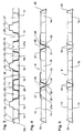
- Figuren 3 - 5
- schematische Längsschnitte des Bodenelementes nach den Schnittlinien III - III, IV - IV und V - V der Figur 2.
Claims (7)
- Bodenelement zum Erstellen von Hohlraumböden für Heizrohre einer Raumheizung sowie für Heiz- und Kühlrohre einer kombinierten Raumheizung und Raumkühlung für Gebäude, das als Kunststoffplatte mit tiefgezogenen Halteelementen auf der Plattenoberseite zum Verlegen der Rohrschlangen von als Heizoder Kühlkreise betreibbaren Rohrkreisläufen einer Raumheizung oder einer kombinierten Raumheizung und Raumkühlung und tiefgezogenen Stütz- und Distanzelementen auf der Plattenunterseite zum Abstützen der Platte auf einem Gebäudeboden und zur Bildung eines Hohlraumes ausgebildet ist, durch den ein Frischluft- und/oder Umluftstrom zur Erwärmung oder Kühlung durch die Fußbodenheizung bzw. Fußbodenkühlung in einen Gebäuderaum geleitet wird, dadurch gekennzeichnet, daß das Bodenelement (8) eine Oberplatte (12) aus Kunststoff mit tiefgezogenen Halteelementen (Fixierkreuze 13) auf der Plattenoberseite (12a) zum Fixieren von Rohrschlangen (9) und tiefgezogenen Stütz- und Distanznocken (14) auf der Plattenunterseite (12b) aufweist und daß die Stütz- und Distanznocken (14) der Oberplatte (12) mit einer auf einen Gebäudeboden (3) auflegbaren Unterplatte (15) aus Kunststoff zu einem an seinen vier Rändern (8a - 8d) oder an zwei gegenüberliegenden Rändern offenen, rechteckigen oder quadratischen Hohlraumelement mit einem Durchströmraum (16) für Frischluft und/oder Umluft verbunden sind.
- Bodenelement nach Anspruch 1, dadurch gekennzeichnet, daß die Oberplatte (12) an den vier Rändern (8a - 8d) des als Hohlraumelement ausgebildeten Bodenelements (8) aus der Plattenunterseite (12b) tiefgezogene, mit der Unterplatte (15) verbundene Noppensegmente (25) aufweist, die als Verbindungselemente für zwei oder vier angrenzende Bodenelemente (8) dienen.
- Bodenelement nach Anspruch 1 und 2, dadurch gekennzeichnet, daß die Stütz- und Distanznocken (14) und die Noppensegmente (25) der Oberplatte (12) mit der Unterplatte (15) verschweißt oder verklebt sind.
- Bodenelement nach einem der Ansprüche 1 bis 3, gekennzeichnet durch aus der Oberseite (12a) der Oberplatte (12) tiefgezogene Fixierkreuze (13) für die Rohrschlangen (9), deren (13) rechtwinklig zueinander angeordnete Haltestege (21 - 24) abgerundete äußere Enden aufweisen.
- Bodenelement nach einem der Ansprüche 1 bis 4, gekennzeichnet durch in die Oberplatte (12) und die Unterplatte (15) in einem Raster deckungsgleich eingeformte Schneidrillen (26) zum Schneiden unterschiedlicher Bodenelementformate.
- Verbindungsplatte für Bodenelemente nach Anspruch 1 bis 5, gekennzeichnet durch an der Unterseite (27a) der Verbindungsplatte (27) angeformte, im Raster der Stütz- und Distanznocken (14) der Bodenelemente (8) angeordnete, hohle Verbindungszapfen (28) mit einer der Nockenform der Nocken (14) der Bodenelemente (8) angepaßten Form sowie einen weiteren zentrisch zwischen den vier Verbindungszapfen (28) an der Plattenunterseite (27a) angeformten, hohlen Fixierzapfen (29) mit einer Form, die der Form der Verbindungsnoppen (30) angepaßt ist, die durch die Noppensegmente (25) an den vier Rändern (8a - 8d) von zwei oder vier angrenzenden Bodenelementen (8) gebildet werden, sowie einen an dem Fixierzapfen (29) angeformten oder einen gesonderten Stift oder Nagel (31) zum Befestigen der Verbindungsplatte (27) mit zwei oder vier durch diese zusammengehaltenen Bodenelementen (8) auf einem Gebäudeboden (3), wobei die Verbindungsplatte (27) mit jeweils zwei Verbindungszapfen (28) in jeweils zwei Stütz- und Distanznocken (14) zweier angrenzender Bodenelemente (8) und mit dem Fixierzapfen (29) in einen von den beiden Bodenelementen (8) gebildeten Verbindungsnoppen (30) eingreift oder die Verbindungsplatte (27) mit jeweils einem Verbindungszapfen (28) in jeweils einen Stütz- und Distanznocken (14) von vier in einem Eckstoß angrenzenden Bodenelementen (8) und mit dem Fixierzapfen (29) in einen von den vier Bodenelementen (8) gebildeten Verbindungsnoppen (30) eingreift und der Befestigungsstift oder Nagel (31) durch ein Loch (32) im Grund (33) eines Verbindungsnoppens (30) von zwei oder vier angrenzenden Bodenelementen (8) in den Gebäudeboden (3) und/oder eine auf diesem verlegte Trittschalldämmung (5) eingeschlagen wird.
- Bodenelement mit Verbindungsplatte nach Anspruch 1 bis 6, gekennzeichnet durch das Abdichten der Stoßfuge (34) zwischen zwei angrenzenden Bodenelementen (8) mit einem Klebeband (35).
Applications Claiming Priority (2)
| Application Number | Priority Date | Filing Date | Title |
|---|---|---|---|
| DE10103001 | 2001-01-24 | ||
| DE10103001A DE10103001C1 (de) | 2001-01-24 | 2001-01-24 | Bodenelement zum Erstellen von Hohlraumböden für Heizrohre einer Raumheizung sowie für Heiz- und Kühlrohre einer kombinierten Raumheizung und Raumkühlung für Gebäude |
Publications (3)
| Publication Number | Publication Date |
|---|---|
| EP1227280A2 true EP1227280A2 (de) | 2002-07-31 |
| EP1227280A3 EP1227280A3 (de) | 2003-05-28 |
| EP1227280B1 EP1227280B1 (de) | 2006-01-04 |
Family
ID=7671513
Family Applications (1)
| Application Number | Title | Priority Date | Filing Date |
|---|---|---|---|
| EP02000756A Expired - Lifetime EP1227280B1 (de) | 2001-01-24 | 2002-01-12 | Bodenelement zum Erstellen von Hohlraumböden für Heizrohre einer Raumheizung sowie für Heiz- und Kühlrohre einer kombinierten Raumheizung und Raumkühlung für Gebäude |
Country Status (5)
| Country | Link |
|---|---|
| EP (1) | EP1227280B1 (de) |
| DE (2) | DE10103001C1 (de) |
| NO (1) | NO20020331L (de) |
| PL (1) | PL198906B1 (de) |
| RU (1) | RU2215858C2 (de) |
Cited By (5)
| Publication number | Priority date | Publication date | Assignee | Title |
|---|---|---|---|---|
| GB2443922A (en) * | 2006-11-16 | 2008-05-21 | Polypipe Building Products Ltd | A heating, cooling and ventilation system |
| WO2010105835A3 (de) * | 2009-03-19 | 2011-02-24 | Wiesboeck Christian | Belagskonstruktion |
| DE102010048939A1 (de) * | 2010-10-19 | 2012-04-19 | Bernd Griesinger | Luftverteilsystem für Gebäude |
| WO2009062268A3 (en) * | 2007-11-12 | 2012-05-24 | Solifort Bvba | Device for heating and/or cooling, as well as a bump plate and a radiation panel which can be used in such device and a method for installing such a device fo heating and/or cooling |
| US20160010875A1 (en) * | 2014-07-10 | 2016-01-14 | Shin Bok Cho | Heating panel with floating floor structure |
Families Citing this family (8)
| Publication number | Priority date | Publication date | Assignee | Title |
|---|---|---|---|---|
| RU2277157C1 (ru) * | 2005-08-17 | 2006-05-27 | Александр Юрьевич Федосеев | Покрытие пола |
| DE102005041405B3 (de) * | 2005-09-01 | 2006-10-05 | Schütz GmbH & Co. KGaA | Bodenelement zum Erstellen von Hohlraumböden mit Heizrohren einer Raumheizung oder mit Heiz- und Kühlrohren einer kombinierten Raumheizung und Raumkühlung |
| MD516Z (ro) * | 2011-07-28 | 2012-12-31 | Коммерческое Общество "Verdelit" Ооо | Pardoseală caldă |
| DE202011106736U1 (de) | 2011-10-13 | 2013-01-14 | herotec GmbH Flächenheizung | Plattenelement zur Erzeugung von Flächenheizungen |
| ITUB20152763A1 (it) * | 2015-08-03 | 2017-02-03 | Silcart Spa | Pannello isolante multistrato per l'installazione di un sistema elettrico di riscaldamento in sottopavimenti o pareti |
| DE202018000718U1 (de) | 2018-02-13 | 2018-04-05 | BID - Beratungsgesellschaft für Investitionsplanung und Durchsetzung mbH | Klimabodenplatte für Zulufträume |
| DE102018001122A1 (de) | 2018-02-13 | 2019-08-14 | BID - Beratungsgesellschaft für Investitionsplanung und Durchsetzung mbH | Klimabodenplatte für Zulufträume |
| US10844613B2 (en) * | 2019-03-19 | 2020-11-24 | Hanover Prest-Paving Company | Paver supporting apparatus |
Citations (1)
| Publication number | Priority date | Publication date | Assignee | Title |
|---|---|---|---|---|
| DE3014390A1 (de) | 1980-04-15 | 1981-10-22 | Polytherm Vertriebsgesellschaft haustechnischer Artikel mbH & Co KG, 4434 Ochtrup | Einrichtung fuer eine flaechenbeheizung |
Family Cites Families (4)
| Publication number | Priority date | Publication date | Assignee | Title |
|---|---|---|---|---|
| DE3329551C1 (de) * | 1983-08-16 | 1985-03-28 | Rolf 4047 Dormagen Buchholz | Fußbodenheizeinrichtung |
| RU2035556C1 (ru) * | 1993-04-26 | 1995-05-20 | Михаил Ефимович Соколов | Сборное здание |
| DE19720971A1 (de) * | 1997-05-20 | 1998-11-26 | Jens Heinrich | Lufterwärmer für Zuluft eines Systems zur kontrollierten Be- und Entlüftung von Gebäuden |
| DE19750277A1 (de) * | 1997-11-13 | 1999-05-20 | Walter Gutjahr | Trägerbahn für Witterungseinflüssen ausgesetzte Boden- oder Wandbeläge |
-
2001
- 2001-01-24 DE DE10103001A patent/DE10103001C1/de not_active Expired - Fee Related
-
2002
- 2002-01-12 EP EP02000756A patent/EP1227280B1/de not_active Expired - Lifetime
- 2002-01-12 DE DE50205486T patent/DE50205486D1/de not_active Expired - Lifetime
- 2002-01-22 NO NO20020331A patent/NO20020331L/no not_active Application Discontinuation
- 2002-01-22 PL PL351809A patent/PL198906B1/pl unknown
- 2002-01-23 RU RU2002102060/03A patent/RU2215858C2/ru not_active IP Right Cessation
Patent Citations (1)
| Publication number | Priority date | Publication date | Assignee | Title |
|---|---|---|---|---|
| DE3014390A1 (de) | 1980-04-15 | 1981-10-22 | Polytherm Vertriebsgesellschaft haustechnischer Artikel mbH & Co KG, 4434 Ochtrup | Einrichtung fuer eine flaechenbeheizung |
Cited By (6)
| Publication number | Priority date | Publication date | Assignee | Title |
|---|---|---|---|---|
| GB2443922A (en) * | 2006-11-16 | 2008-05-21 | Polypipe Building Products Ltd | A heating, cooling and ventilation system |
| WO2009062268A3 (en) * | 2007-11-12 | 2012-05-24 | Solifort Bvba | Device for heating and/or cooling, as well as a bump plate and a radiation panel which can be used in such device and a method for installing such a device fo heating and/or cooling |
| WO2010105835A3 (de) * | 2009-03-19 | 2011-02-24 | Wiesboeck Christian | Belagskonstruktion |
| DE102010048939A1 (de) * | 2010-10-19 | 2012-04-19 | Bernd Griesinger | Luftverteilsystem für Gebäude |
| EP2444752A3 (de) * | 2010-10-19 | 2015-03-04 | Marcus Klimmek | Luftführungsbaugruppe für ein Luftverteilsystem, ein Luftverteilsystem für Gebäude mit dieser Baugruppe, ein Verfahren zum Anordnen der Luftführungsbaugruppe sowie ein Verfahren zum Betrieb eines Luftverteilsystems |
| US20160010875A1 (en) * | 2014-07-10 | 2016-01-14 | Shin Bok Cho | Heating panel with floating floor structure |
Also Published As
| Publication number | Publication date |
|---|---|
| EP1227280A3 (de) | 2003-05-28 |
| PL351809A1 (en) | 2002-07-29 |
| PL198906B1 (pl) | 2008-07-31 |
| DE10103001C1 (de) | 2002-10-24 |
| NO20020331D0 (no) | 2002-01-22 |
| DE50205486D1 (de) | 2006-03-30 |
| EP1227280B1 (de) | 2006-01-04 |
| RU2215858C2 (ru) | 2003-11-10 |
| NO20020331L (no) | 2002-07-25 |
Similar Documents
| Publication | Publication Date | Title |
|---|---|---|
| DE10103001C1 (de) | Bodenelement zum Erstellen von Hohlraumböden für Heizrohre einer Raumheizung sowie für Heiz- und Kühlrohre einer kombinierten Raumheizung und Raumkühlung für Gebäude | |
| DE3317731A1 (de) | Bodenplatte | |
| EP0074490B1 (de) | Fussboden mit integrierter Warmwasser-Fussbodenheizung | |
| DE10049172A1 (de) | Bauplatte | |
| DE2248228A1 (de) | Regelbare fluessigkeitsflaechenheizung mit gleichmaessiger oberflaechentemperatur | |
| DE3720554A1 (de) | Plattenfoermiges bauelement | |
| WO2008128262A1 (de) | Plattenförmiges verkleidungselement für eine mauer und mauerverkleidung | |
| DE10357937B4 (de) | Systemplatte aus Kunststoff zum Verlegen von Kunststoffrohren der Heiz- bzw. Kühlkreise von Flächen-Heiz- und Kühlinstallationen | |
| DE2930426C2 (de) | Fußbodenelement für eine Fußbodenheizung | |
| DE3919862A1 (de) | Verlorene schalungen | |
| DE102005041405B3 (de) | Bodenelement zum Erstellen von Hohlraumböden mit Heizrohren einer Raumheizung oder mit Heiz- und Kühlrohren einer kombinierten Raumheizung und Raumkühlung | |
| EP0111763B1 (de) | Fliese, Fliesenbaustein | |
| EP1344987A2 (de) | Flächenheiz- und Kühlelement | |
| EP2210996B1 (de) | Bodenkonstruktion | |
| DE19640514A1 (de) | Mehrschichtige Systembauplatten für Heiz- und Kühlflächen | |
| DE202007017185U1 (de) | Wärmeverbundsystem sowie ein Flächenheizungs/-kühlungs-Baukastensystem mit einem derartigen Wärmeverbundsystem | |
| CH687666A5 (de) | Heizbare Sitzbank. | |
| DE1961882A1 (de) | Fussboden- oder Wandheizung | |
| DE8400402U1 (de) | Sandwich-Wärmetauscher | |
| DE3540713A1 (de) | Wandbaustein | |
| AT515868B1 (de) | Mobile Fußboden-Heizmatten | |
| DE3319500C2 (de) | Luft-Fußbodenheizung | |
| DE10205668C1 (de) | Anordnung eines Fußbodens und Verfahren zu seiner Herstellung | |
| DE3238757C2 (de) | Warmluft-Heizungsanlage | |
| AT6507U1 (de) | Heizelement |
Legal Events
| Date | Code | Title | Description |
|---|---|---|---|
| PUAI | Public reference made under article 153(3) epc to a published international application that has entered the european phase |
Free format text: ORIGINAL CODE: 0009012 |
|
| AK | Designated contracting states |
Kind code of ref document: A2 Designated state(s): AT BE CH CY DE DK ES FI FR GB GR IE IT LI LU MC NL PT SE TR |
|
| AX | Request for extension of the european patent |
Free format text: AL;LT;LV;MK;RO;SI |
|
| PUAL | Search report despatched |
Free format text: ORIGINAL CODE: 0009013 |
|
| AK | Designated contracting states |
Designated state(s): AT BE CH CY DE DK ES FI FR GB GR IE IT LI LU MC NL PT SE TR |
|
| AX | Request for extension of the european patent |
Extension state: AL LT LV MK RO SI |
|
| RIC1 | Information provided on ipc code assigned before grant |
Ipc: 7F 24D 5/10 B Ipc: 7F 24D 3/10 A Ipc: 7F 24D 3/14 B |
|
| 17P | Request for examination filed |
Effective date: 20031027 |
|
| AKX | Designation fees paid |
Designated state(s): DE DK ES FI FR GB IT SE |
|
| GRAP | Despatch of communication of intention to grant a patent |
Free format text: ORIGINAL CODE: EPIDOSNIGR1 |
|
| GRAS | Grant fee paid |
Free format text: ORIGINAL CODE: EPIDOSNIGR3 |
|
| GRAA | (expected) grant |
Free format text: ORIGINAL CODE: 0009210 |
|
| AK | Designated contracting states |
Kind code of ref document: B1 Designated state(s): DE DK ES FI FR GB IT SE |
|
| PG25 | Lapsed in a contracting state [announced via postgrant information from national office to epo] |
Ref country code: IT Free format text: LAPSE BECAUSE OF FAILURE TO SUBMIT A TRANSLATION OF THE DESCRIPTION OR TO PAY THE FEE WITHIN THE PRE;WARNING: LAPSES OF ITALIAN PATENTS WITH EFFECTIVE DATE BEFORE 2007 MAY HAVE OCCURRED AT ANY TIME BEFORE 2007. THE CORRECT EFFECTIVE DATE MAY BE DIFFERENT FROM THE ONE RECORDED.SCRIBED TIME-LIMIT Effective date: 20060104 Ref country code: FI Free format text: LAPSE BECAUSE OF FAILURE TO SUBMIT A TRANSLATION OF THE DESCRIPTION OR TO PAY THE FEE WITHIN THE PRESCRIBED TIME-LIMIT Effective date: 20060104 Ref country code: GB Free format text: LAPSE BECAUSE OF FAILURE TO SUBMIT A TRANSLATION OF THE DESCRIPTION OR TO PAY THE FEE WITHIN THE PRESCRIBED TIME-LIMIT Effective date: 20060104 |
|
| REG | Reference to a national code |
Ref country code: GB Ref legal event code: FG4D Free format text: NOT ENGLISH |
|
| REF | Corresponds to: |
Ref document number: 50205486 Country of ref document: DE Date of ref document: 20060330 Kind code of ref document: P |
|
| PG25 | Lapsed in a contracting state [announced via postgrant information from national office to epo] |
Ref country code: DK Free format text: LAPSE BECAUSE OF FAILURE TO SUBMIT A TRANSLATION OF THE DESCRIPTION OR TO PAY THE FEE WITHIN THE PRESCRIBED TIME-LIMIT Effective date: 20060404 Ref country code: SE Free format text: LAPSE BECAUSE OF FAILURE TO SUBMIT A TRANSLATION OF THE DESCRIPTION OR TO PAY THE FEE WITHIN THE PRESCRIBED TIME-LIMIT Effective date: 20060404 |
|
| PG25 | Lapsed in a contracting state [announced via postgrant information from national office to epo] |
Ref country code: ES Free format text: LAPSE BECAUSE OF FAILURE TO SUBMIT A TRANSLATION OF THE DESCRIPTION OR TO PAY THE FEE WITHIN THE PRESCRIBED TIME-LIMIT Effective date: 20060415 |
|
| GBV | Gb: ep patent (uk) treated as always having been void in accordance with gb section 77(7)/1977 [no translation filed] |
Effective date: 20060104 |
|
| PLBE | No opposition filed within time limit |
Free format text: ORIGINAL CODE: 0009261 |
|
| STAA | Information on the status of an ep patent application or granted ep patent |
Free format text: STATUS: NO OPPOSITION FILED WITHIN TIME LIMIT |
|
| 26N | No opposition filed |
Effective date: 20061005 |
|
| EN | Fr: translation not filed | ||
| PG25 | Lapsed in a contracting state [announced via postgrant information from national office to epo] |
Ref country code: FR Free format text: LAPSE BECAUSE OF FAILURE TO SUBMIT A TRANSLATION OF THE DESCRIPTION OR TO PAY THE FEE WITHIN THE PRESCRIBED TIME-LIMIT Effective date: 20070223 |
|
| PG25 | Lapsed in a contracting state [announced via postgrant information from national office to epo] |
Ref country code: FR Free format text: LAPSE BECAUSE OF FAILURE TO SUBMIT A TRANSLATION OF THE DESCRIPTION OR TO PAY THE FEE WITHIN THE PRESCRIBED TIME-LIMIT Effective date: 20060131 |
|
| PG25 | Lapsed in a contracting state [announced via postgrant information from national office to epo] |
Ref country code: FR Free format text: LAPSE BECAUSE OF FAILURE TO SUBMIT A TRANSLATION OF THE DESCRIPTION OR TO PAY THE FEE WITHIN THE PRESCRIBED TIME-LIMIT Effective date: 20060104 |
|
| PGFP | Annual fee paid to national office [announced via postgrant information from national office to epo] |
Ref country code: DE Payment date: 20210325 Year of fee payment: 20 |
|
| REG | Reference to a national code |
Ref country code: DE Ref legal event code: R071 Ref document number: 50205486 Country of ref document: DE |