EP1227291A2 - Echangeur de chaleur et procédé de fabrication - Google Patents
Echangeur de chaleur et procédé de fabrication Download PDFInfo
- Publication number
- EP1227291A2 EP1227291A2 EP01127879A EP01127879A EP1227291A2 EP 1227291 A2 EP1227291 A2 EP 1227291A2 EP 01127879 A EP01127879 A EP 01127879A EP 01127879 A EP01127879 A EP 01127879A EP 1227291 A2 EP1227291 A2 EP 1227291A2
- Authority
- EP
- European Patent Office
- Prior art keywords
- flat tubes
- flat
- flat tube
- collecting
- heat exchanger
- Prior art date
- Legal status (The legal status is an assumption and is not a legal conclusion. Google has not performed a legal analysis and makes no representation as to the accuracy of the status listed.)
- Granted
Links
- 238000000034 method Methods 0.000 title claims abstract description 13
- 238000004519 manufacturing process Methods 0.000 title claims description 4
- 230000008569 process Effects 0.000 claims abstract description 9
- 238000005476 soldering Methods 0.000 claims description 5
- 230000006835 compression Effects 0.000 claims description 4
- 238000007906 compression Methods 0.000 claims description 4
- 238000000926 separation method Methods 0.000 claims description 3
- 238000005452 bending Methods 0.000 abstract description 3
- 230000003247 decreasing effect Effects 0.000 abstract 1
- 238000001816 cooling Methods 0.000 description 5
- 239000002826 coolant Substances 0.000 description 4
- 230000004048 modification Effects 0.000 description 4
- 238000012986 modification Methods 0.000 description 4
- 238000007493 shaping process Methods 0.000 description 2
- 229910000679 solder Inorganic materials 0.000 description 2
- 230000007704 transition Effects 0.000 description 2
- 229910052782 aluminium Inorganic materials 0.000 description 1
- XAGFODPZIPBFFR-UHFFFAOYSA-N aluminium Chemical compound [Al] XAGFODPZIPBFFR-UHFFFAOYSA-N 0.000 description 1
- 230000000694 effects Effects 0.000 description 1
- 229910052751 metal Inorganic materials 0.000 description 1
- 239000002184 metal Substances 0.000 description 1
- 230000009467 reduction Effects 0.000 description 1
Images


Classifications
-
- F—MECHANICAL ENGINEERING; LIGHTING; HEATING; WEAPONS; BLASTING
- F28—HEAT EXCHANGE IN GENERAL
- F28F—DETAILS OF HEAT-EXCHANGE AND HEAT-TRANSFER APPARATUS, OF GENERAL APPLICATION
- F28F9/00—Casings; Header boxes; Auxiliary supports for elements; Auxiliary members within casings
- F28F9/02—Header boxes; End plates
- F28F9/0219—Arrangements for sealing end plates into casing or header box; Header box sub-elements
- F28F9/0221—Header boxes or end plates formed by stacked elements
-
- Y—GENERAL TAGGING OF NEW TECHNOLOGICAL DEVELOPMENTS; GENERAL TAGGING OF CROSS-SECTIONAL TECHNOLOGIES SPANNING OVER SEVERAL SECTIONS OF THE IPC; TECHNICAL SUBJECTS COVERED BY FORMER USPC CROSS-REFERENCE ART COLLECTIONS [XRACs] AND DIGESTS
- Y10—TECHNICAL SUBJECTS COVERED BY FORMER USPC
- Y10T—TECHNICAL SUBJECTS COVERED BY FORMER US CLASSIFICATION
- Y10T29/00—Metal working
- Y10T29/49—Method of mechanical manufacture
- Y10T29/4935—Heat exchanger or boiler making
- Y10T29/49373—Tube joint and tube plate structure
Definitions
- the invention relates to a heat exchanger for motor vehicles with a finned flat tube block, consisting of flat tubes with fins arranged therebetween, shaped ends of the flat tubes opening into opposing collecting or deflecting boxes and with the long sides of the shaped ends with one another and with the narrow sides at the connecting edges the collecting or deflection boxes are connected by means of soldering; the ends of the flat tubes have at least one separating cut which divides the ends of the flat tubes into two parts; at least one of the separated parts of each flat tube has a bend transversely to the longitudinal direction, which leads to a connecting surface between the long side of the flat tube and the long side of the part of the adjacent flat tube; the collecting or deflection boxes with their connecting edges extend beyond the bend,
- the invention further relates to a production method for the heat exchanger.
- the heat exchanger and the method are the subject of the previously unpublished patent applications DE 100 19 268.8 and DE 100 60 006.9. If such a heat exchanger is used as a coolant cooler, the small diameter of the flat tubes is relatively small, often in the range of less than 2 mm, so that the two parts created by the separating cut, which serve for the soldered connection with the connecting edges of the collecting or deflection boxes , also form very small areas that lead to unsatisfactory solder connections. For example, from FIGS. 4 and 6 of DE 195 43 986 A1 it can be seen that the large diameter of the shaped ends of the flat tubes is reduced to such an extent that the collecting or deflecting boxes are significantly narrower than the finned flat tube block.
- the object of the present invention is to eliminate or to mitigate the above disadvantages.
- the ends of the flat tubes are stepped twice within their forming section, one step being able to be produced by means of an upsetting and widening process and the other step being made by the separating cut and the bending of at least one of the separated parts.
- the manufacturing method in connection with the preamble of claim 5 according to the invention provides that the ends of the flat tubes are subjected to an upsetting and widening operation prior to the separation or in one operation with the separation, the small diameter of the flat tubes expanding and the large diameter of the flat tubes is reduced, and that the at least one separating cut is made within the forming section in the narrow sides of the ends of the flat tubes.
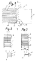
- the finned flat tube block of the heat exchanger 1 consists of flat tubes 2 and corrugated fins 3 arranged between them.
- the partial view in FIG. 1 only shows a collecting box 5 .
- the other header box 5 is arranged identically at the opposite ends 4 of the flat tubes 2 .
- All parts of this embodiment are made of aluminum and are plated with solder as required.
- the collecting boxes 5 are of the simplest form, so that they can be produced very inexpensively using known processes in metal forming.
- Each collecting box 5 has two connecting edges 7 with which it overlaps the narrow sides 11 of the flat tubes 2 at the ends 4 in the forming section 12 (FIG. 6).
- FIGS. 6 In the exemplary embodiment from FIGS.
- the ends 4 of the flat tubes 2 are stepped twice within their forming section 12 on both longitudinal sides 6 , one step 13 using a compression and expansion process and the other step 14 using a single separating cut 8 both narrow sides 11 of the flat tubes 2 and by the bend 9 of both parts 2a; 2b is made.
- the width B of the collecting tanks 5 corresponds to the depth T of the cooling network, which can be seen from FIG. 3 and also from FIG. 5, which shows the cooling network without a collecting tank 5 . Therefore, the heat exchanger of this exemplary embodiment is a coolant-air cooler which has a relatively small depth T of the cooling network, which is approximately 25 mm. Furthermore, this has flat tubes 2, the small diameter d of which is less than 2 mm.
- FIG. 2 shows a section through FIG.
- FIG. 3 shows another section through FIG. 1, which runs just above the second gradation 14 or through the connecting surfaces 10 , which are formed by the longitudinal sides 6 of adjacent flat tube ends 4 lying against one another.
- the gradation 14 arises as a result of the turn 9 of the parts 2a and 2b.
- the degree of deformation of the compression and expansion process is significantly less than in known heat exchangers, ie the large diameter D of the flat tube 2 has been reduced significantly less and the small diameter d has been expanded significantly less.
- the forming section 12 could also extend deeper into the flat tube 2 than is shown in FIGS. 6 and 7. This would result in even larger areas for the soldered connection between the narrow sides 11 and the connecting edges 7.
- the result of the described method step (expansion process) is shown in FIG. 7.
- the figure also shows the only separating cut 8 in the exemplary embodiments , which is made centrally in the narrow sides 11 of the flat tube 2 , specifically within the forming section 12 .
- the separating cut is significantly shorter than the forming section 12.
- the two parts 2a and 2b are bent and the step 14 is formed. 8
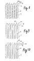
- FIG. 10 shows a similar modification in which, in contrast to FIG. 8, the forming section 12 has been designed asymmetrically to the flat tube 2 .
- FIG. 9 also shows an asymmetrical forming section 12, but both parts 2a and 2b have been bent there.
- the dimensional design of the gradations 13, 14 and the depth of the forming section 12 can differ in the variants shown. Therefore, the designer has extensive options for designing the heat exchanger.
- the gradations 13, 14 lead to a smooth transition for the coolant when entering the flat tubes 2. Therefore, they contribute to reducing the pressure loss.
- the frame 15 has longitudinal and transverse sides 16, 17 and is pushed over the ends 4 of the flat tubes 2 and connected to all the other parts at the ends 4 in a soldering operation.
- This development enables the use of plastic collecting boxes 5 .
- the frame 15 has a U-shaped cross section, as shown in FIGS. 11 and 12, which serves to receive and mechanically fasten the edge of the collecting box 5 , not shown.
- tabs 18 are bent, which can hold the collecting box 5 firmly and tightly in the frame 15 .
Landscapes
- Engineering & Computer Science (AREA)
- Physics & Mathematics (AREA)
- Thermal Sciences (AREA)
- Mechanical Engineering (AREA)
- General Engineering & Computer Science (AREA)
- Heat-Exchange Devices With Radiators And Conduit Assemblies (AREA)
- Details Of Heat-Exchange And Heat-Transfer (AREA)
Applications Claiming Priority (2)
| Application Number | Priority Date | Filing Date | Title |
|---|---|---|---|
| DE10103570 | 2001-01-26 | ||
| DE10103570A DE10103570A1 (de) | 2001-01-26 | 2001-01-26 | Wärmetauscher und Herstellungsverfahren |
Publications (3)
| Publication Number | Publication Date |
|---|---|
| EP1227291A2 true EP1227291A2 (fr) | 2002-07-31 |
| EP1227291A3 EP1227291A3 (fr) | 2004-05-12 |
| EP1227291B1 EP1227291B1 (fr) | 2006-06-21 |
Family
ID=7671869
Family Applications (1)
| Application Number | Title | Priority Date | Filing Date |
|---|---|---|---|
| EP01127879A Expired - Lifetime EP1227291B1 (fr) | 2001-01-26 | 2001-11-23 | Echangeur de chaleur et procédé de fabrication |
Country Status (3)
| Country | Link |
|---|---|
| US (1) | US6739386B2 (fr) |
| EP (1) | EP1227291B1 (fr) |
| DE (2) | DE10103570A1 (fr) |
Cited By (2)
| Publication number | Priority date | Publication date | Assignee | Title |
|---|---|---|---|---|
| CN1873361B (zh) * | 2005-05-17 | 2011-07-06 | 三电有限公司 | 用于换热器的管及其制造方法 |
| EP2998685A3 (fr) * | 2014-09-22 | 2016-03-30 | MAHLE International GmbH | Échangeur thermique |
Families Citing this family (12)
| Publication number | Priority date | Publication date | Assignee | Title |
|---|---|---|---|---|
| DE10147192A1 (de) * | 2001-09-25 | 2003-04-17 | Modine Mfg Co | Wärmeaustauscher mit einem Rippen-Flachrohr-Block und Herstellungsverfahren |
| US20050161207A1 (en) * | 2004-01-26 | 2005-07-28 | Valeo, Inc. | Heat exchanger manifold with formed corner joint |
| US7506683B2 (en) * | 2004-05-21 | 2009-03-24 | Valeo, Inc. | Multi-type fins for multi-exchangers |
| US8925625B2 (en) * | 2007-07-11 | 2015-01-06 | Denso Corporation | Heat exchanger |
| US20100199955A1 (en) * | 2009-02-06 | 2010-08-12 | Paccar Inc | Charge air cooler |
| GB2509762B (en) | 2013-01-14 | 2015-02-04 | Halla Visteon Climate Control | Tube for Heat Exchanger |
| JP6209078B2 (ja) * | 2013-12-20 | 2017-10-04 | 株式会社ティラド | ヘッダプレートレス型熱交換器 |
| JP6567524B2 (ja) * | 2014-07-30 | 2019-08-28 | 株式会社ティラド | ヘッダープレートレス熱交換器の偏平チューブ |
| US9816767B2 (en) | 2016-01-12 | 2017-11-14 | Hamilton Sundstrand Corporation | Tubes and manifolds for heat exchangers |
| DE112019000761T5 (de) * | 2018-03-30 | 2020-11-12 | T.Rad Co., Ltd. | Headerplattenloser wärmetauscher |
| US11079181B2 (en) * | 2018-05-03 | 2021-08-03 | Raytheon Technologies Corporation | Cast plate heat exchanger with tapered walls |
| KR102674359B1 (ko) * | 2022-10-20 | 2024-06-12 | (주)신한아펙스 | 판형 열교환기 및 그 제조방법 |
Citations (3)
| Publication number | Priority date | Publication date | Assignee | Title |
|---|---|---|---|---|
| DE19543986A1 (de) | 1995-11-25 | 1997-05-28 | Behr Gmbh & Co | Wärmetauscher und ein Verfahren zur Herstellung eines Wärmetauschers |
| DE10019268A1 (de) | 2000-03-31 | 2001-12-13 | Modine Mfg Co | Kühler für Kraftfahrzeuge |
| DE10060006A1 (de) | 2000-12-02 | 2002-06-13 | Modine Mfg Co | Wärmetauscher |
Family Cites Families (12)
| Publication number | Priority date | Publication date | Assignee | Title |
|---|---|---|---|---|
| DE584678C (de) * | 1932-03-22 | 1933-09-22 | Buckau R Wolf Akt Ges Maschf | Dampfbeheizter Roehrentrockner Schulzscher Bauart |
| CH378353A (de) * | 1960-09-01 | 1964-06-15 | Urech Karl | Wärmeaustauscher mit plattenförmigen Austauschelementen |
| DE2061682A1 (en) * | 1969-12-17 | 1971-07-15 | Murex Ltd | Heat exchange pipework assembly with at - least three pipes |
| US4206806A (en) * | 1976-03-15 | 1980-06-10 | Akira Togashi | Heat-conducting oval pipes in heat exchangers |
| JPS5860196A (ja) * | 1981-09-30 | 1983-04-09 | Toshiba Corp | 熱交換器 |
| US4458749A (en) * | 1983-04-18 | 1984-07-10 | Ex-Cell-O Corporation | Radiator having reinforced tubes |
| FR2570814B1 (fr) * | 1984-09-25 | 1986-12-19 | Valeo | Echangeur de chaleur a faisceau de tubes, en particulier pour vehicule automobile |
| JPS6447287A (en) * | 1987-08-13 | 1989-02-21 | Fuji Electric Co Ltd | Star-delta starting method for induction motor |
| FR2705143B1 (fr) * | 1993-05-11 | 1995-06-23 | Valeo Thermique Moteur Sa | Echangeur de chaleur notamment pour vehicule automobile. |
| JP3125834B2 (ja) * | 1993-09-01 | 2001-01-22 | 株式会社デンソー | 熱交換器およびその製造方法 |
| FR2715216B1 (fr) * | 1994-01-20 | 1996-02-16 | Valeo Thermique Moteur Sa | Tube d'échangeur de chaleur, procédé pour sa conformation et échangeur de chaleur comprenant de tels tubes. |
| DE4445590C2 (de) * | 1994-12-20 | 2001-02-01 | Behr Gmbh & Co | Verfahren zum Aufweiten der Rohrenden von Rohren eines Wärmetauschers, Werkzeug zur Durchführung des Verfahrens sowie nach dem Verfahren und mit dem Werkzeug hergestellter Wärmetauscher |
-
2001
- 2001-01-26 DE DE10103570A patent/DE10103570A1/de not_active Withdrawn
- 2001-11-23 DE DE50110241T patent/DE50110241D1/de not_active Expired - Fee Related
- 2001-11-23 EP EP01127879A patent/EP1227291B1/fr not_active Expired - Lifetime
-
2002
- 2002-01-23 US US10/057,480 patent/US6739386B2/en not_active Expired - Fee Related
Patent Citations (3)
| Publication number | Priority date | Publication date | Assignee | Title |
|---|---|---|---|---|
| DE19543986A1 (de) | 1995-11-25 | 1997-05-28 | Behr Gmbh & Co | Wärmetauscher und ein Verfahren zur Herstellung eines Wärmetauschers |
| DE10019268A1 (de) | 2000-03-31 | 2001-12-13 | Modine Mfg Co | Kühler für Kraftfahrzeuge |
| DE10060006A1 (de) | 2000-12-02 | 2002-06-13 | Modine Mfg Co | Wärmetauscher |
Cited By (3)
| Publication number | Priority date | Publication date | Assignee | Title |
|---|---|---|---|---|
| CN1873361B (zh) * | 2005-05-17 | 2011-07-06 | 三电有限公司 | 用于换热器的管及其制造方法 |
| EP2998685A3 (fr) * | 2014-09-22 | 2016-03-30 | MAHLE International GmbH | Échangeur thermique |
| US10837708B2 (en) | 2014-09-22 | 2020-11-17 | Mahle International Gmbh | Plate type heat exchanger for exhaust gas |
Also Published As
| Publication number | Publication date |
|---|---|
| EP1227291A3 (fr) | 2004-05-12 |
| DE50110241D1 (de) | 2006-08-03 |
| EP1227291B1 (fr) | 2006-06-21 |
| US20020108742A1 (en) | 2002-08-15 |
| DE10103570A1 (de) | 2002-08-01 |
| US6739386B2 (en) | 2004-05-25 |
Similar Documents
| Publication | Publication Date | Title |
|---|---|---|
| DE60219538T2 (de) | Wärmetauscher | |
| DE60111469T2 (de) | Wärmetauscher und Verfahren zu dessen Herstellung | |
| DE69202964T2 (de) | Wärmetauscher. | |
| DE69401434T2 (de) | Rippenröhre für wärmetauscher für klima und kühlungsanlagen und entsprechende wärmetauscher | |
| EP0798529B1 (fr) | Tube pour échangeur de chaleur | |
| DE60217515T2 (de) | Metallplatte zur herstellung eines flachrohrs, flachrohr und verfahren zur herstellung des flachrohrs | |
| DE69210452T2 (de) | Wärmetauscher mit Rohrbündel, insbesondere für Kraftfahrzeug | |
| DE69708730T2 (de) | Wärmetauscher und Verfahren zu seiner Herstellung | |
| DE69215506T2 (de) | Wärmetauschersammlerrohr und Verfahren zu dessen Herstellung | |
| DE69804007T2 (de) | Verfahren zum zusammensetzen von wärmetauscher | |
| EP1227291B1 (fr) | Echangeur de chaleur et procédé de fabrication | |
| DE10315371A1 (de) | Wärmeübertrager | |
| DE19543986A1 (de) | Wärmetauscher und ein Verfahren zur Herstellung eines Wärmetauschers | |
| DE69600309T2 (de) | Flachrohr für einen wärmetauscher | |
| DE69203388T2 (de) | Verfahren zur Herstellung eines Rohrbündelwärmetauschers. | |
| EP0565813B1 (fr) | Echangeur de chaleur | |
| EP1774245A1 (fr) | Echangeur thermique integralement metallique et procede de fabrication associe | |
| DE10150213A1 (de) | Stranggepreßtes Profil, insbesondere für Wärmetauscher | |
| DE4009780A1 (de) | Waermetauscher | |
| EP1148312B1 (fr) | Radiateur de véhicules | |
| DE19820937A1 (de) | Flachrohr sowie Verfahren und Vorrichtung zu seiner Herstellung | |
| EP1296109B1 (fr) | Echangeur de chaleur avec un bloc de tubes plats ailettés et la méthode d'assemblage associée | |
| DE69721101T2 (de) | Verflüssiger für Klimaanlagen von Fahrzeugen | |
| WO2003098142A1 (fr) | Echangeur thermique et son procede de production | |
| DE69903241T2 (de) | Wärmetauscher, insbesondere verflüssiger für kraftfahrzeug und verfahren zu dessen herstellung |
Legal Events
| Date | Code | Title | Description |
|---|---|---|---|
| PUAI | Public reference made under article 153(3) epc to a published international application that has entered the european phase |
Free format text: ORIGINAL CODE: 0009012 |
|
| AK | Designated contracting states |
Kind code of ref document: A2 Designated state(s): AT BE CH CY DE DK ES FI FR GB GR IE IT LI LU MC NL PT SE TR |
|
| AX | Request for extension of the european patent |
Free format text: AL;LT;LV;MK;RO;SI |
|
| PUAL | Search report despatched |
Free format text: ORIGINAL CODE: 0009013 |
|
| AK | Designated contracting states |
Kind code of ref document: A3 Designated state(s): AT BE CH CY DE DK ES FI FR GB GR IE IT LI LU MC NL PT SE TR |
|
| AX | Request for extension of the european patent |
Extension state: AL LT LV MK RO SI |
|
| RIC1 | Information provided on ipc code assigned before grant |
Ipc: 7F 28F 9/02 A Ipc: 7F 28F 1/02 B |
|
| 17P | Request for examination filed |
Effective date: 20041112 |
|
| AKX | Designation fees paid |
Designated state(s): DE ES FR GB IT SE |
|
| GRAP | Despatch of communication of intention to grant a patent |
Free format text: ORIGINAL CODE: EPIDOSNIGR1 |
|
| GRAS | Grant fee paid |
Free format text: ORIGINAL CODE: EPIDOSNIGR3 |
|
| GRAA | (expected) grant |
Free format text: ORIGINAL CODE: 0009210 |
|
| AK | Designated contracting states |
Kind code of ref document: B1 Designated state(s): DE ES FR GB IT SE |
|
| PG25 | Lapsed in a contracting state [announced via postgrant information from national office to epo] |
Ref country code: IT Free format text: LAPSE BECAUSE OF FAILURE TO SUBMIT A TRANSLATION OF THE DESCRIPTION OR TO PAY THE FEE WITHIN THE PRESCRIBED TIME-LIMIT;WARNING: LAPSES OF ITALIAN PATENTS WITH EFFECTIVE DATE BEFORE 2007 MAY HAVE OCCURRED AT ANY TIME BEFORE 2007. THE CORRECT EFFECTIVE DATE MAY BE DIFFERENT FROM THE ONE RECORDED. Effective date: 20060621 |
|
| REG | Reference to a national code |
Ref country code: GB Ref legal event code: FG4D Free format text: NOT ENGLISH |
|
| REF | Corresponds to: |
Ref document number: 50110241 Country of ref document: DE Date of ref document: 20060803 Kind code of ref document: P |
|
| PG25 | Lapsed in a contracting state [announced via postgrant information from national office to epo] |
Ref country code: SE Free format text: LAPSE BECAUSE OF FAILURE TO SUBMIT A TRANSLATION OF THE DESCRIPTION OR TO PAY THE FEE WITHIN THE PRESCRIBED TIME-LIMIT Effective date: 20060921 |
|
| PG25 | Lapsed in a contracting state [announced via postgrant information from national office to epo] |
Ref country code: ES Free format text: LAPSE BECAUSE OF FAILURE TO SUBMIT A TRANSLATION OF THE DESCRIPTION OR TO PAY THE FEE WITHIN THE PRESCRIBED TIME-LIMIT Effective date: 20061002 |
|
| GBT | Gb: translation of ep patent filed (gb section 77(6)(a)/1977) |
Effective date: 20060924 |
|
| ET | Fr: translation filed | ||
| PLBE | No opposition filed within time limit |
Free format text: ORIGINAL CODE: 0009261 |
|
| STAA | Information on the status of an ep patent application or granted ep patent |
Free format text: STATUS: NO OPPOSITION FILED WITHIN TIME LIMIT |
|
| 26N | No opposition filed |
Effective date: 20070322 |
|
| PGFP | Annual fee paid to national office [announced via postgrant information from national office to epo] |
Ref country code: DE Payment date: 20081210 Year of fee payment: 8 |
|
| PGFP | Annual fee paid to national office [announced via postgrant information from national office to epo] |
Ref country code: FR Payment date: 20081117 Year of fee payment: 8 |
|
| PGFP | Annual fee paid to national office [announced via postgrant information from national office to epo] |
Ref country code: GB Payment date: 20081119 Year of fee payment: 8 |
|
| GBPC | Gb: european patent ceased through non-payment of renewal fee |
Effective date: 20091123 |
|
| REG | Reference to a national code |
Ref country code: FR Ref legal event code: ST Effective date: 20100730 |
|
| PG25 | Lapsed in a contracting state [announced via postgrant information from national office to epo] |
Ref country code: FR Free format text: LAPSE BECAUSE OF NON-PAYMENT OF DUE FEES Effective date: 20091130 |
|
| PG25 | Lapsed in a contracting state [announced via postgrant information from national office to epo] |
Ref country code: DE Free format text: LAPSE BECAUSE OF NON-PAYMENT OF DUE FEES Effective date: 20100601 |
|
| PG25 | Lapsed in a contracting state [announced via postgrant information from national office to epo] |
Ref country code: GB Free format text: LAPSE BECAUSE OF NON-PAYMENT OF DUE FEES Effective date: 20091123 |