EP1227355B1 - Microscope pour observation à grand angle, notamment de chirurgie ophthalmologique - Google Patents
Microscope pour observation à grand angle, notamment de chirurgie ophthalmologique Download PDFInfo
- Publication number
- EP1227355B1 EP1227355B1 EP01121232A EP01121232A EP1227355B1 EP 1227355 B1 EP1227355 B1 EP 1227355B1 EP 01121232 A EP01121232 A EP 01121232A EP 01121232 A EP01121232 A EP 01121232A EP 1227355 B1 EP1227355 B1 EP 1227355B1
- Authority
- EP
- European Patent Office
- Prior art keywords
- microscope
- beam path
- microscope according
- lens
- eye
- Prior art date
- Legal status (The legal status is an assumption and is not a legal conclusion. Google has not performed a legal analysis and makes no representation as to the accuracy of the status listed.)
- Expired - Lifetime
Links
- 238000007689 inspection Methods 0.000 title 1
- 230000003287 optical effect Effects 0.000 claims description 15
- 238000001356 surgical procedure Methods 0.000 description 5
- 238000003384 imaging method Methods 0.000 description 3
- 230000008901 benefit Effects 0.000 description 2
- 230000006978 adaptation Effects 0.000 description 1
- 230000004075 alteration Effects 0.000 description 1
- 230000008859 change Effects 0.000 description 1
- 230000008878 coupling Effects 0.000 description 1
- 238000010168 coupling process Methods 0.000 description 1
- 238000005859 coupling reaction Methods 0.000 description 1
- 238000003745 diagnosis Methods 0.000 description 1
- 238000003780 insertion Methods 0.000 description 1
- 230000037431 insertion Effects 0.000 description 1
- 230000007246 mechanism Effects 0.000 description 1
- 238000000034 method Methods 0.000 description 1
Images


Classifications
-
- A—HUMAN NECESSITIES
- A61—MEDICAL OR VETERINARY SCIENCE; HYGIENE
- A61B—DIAGNOSIS; SURGERY; IDENTIFICATION
- A61B3/00—Apparatus for testing the eyes; Instruments for examining the eyes
- A61B3/10—Objective types, i.e. instruments for examining the eyes independent of the patients' perceptions or reactions
- A61B3/13—Ophthalmic microscopes
-
- G—PHYSICS
- G02—OPTICS
- G02B—OPTICAL ELEMENTS, SYSTEMS OR APPARATUS
- G02B17/00—Systems with reflecting surfaces, with or without refracting elements
- G02B17/02—Catoptric systems, e.g. image erecting and reversing system
- G02B17/04—Catoptric systems, e.g. image erecting and reversing system using prisms only
-
- G—PHYSICS
- G02—OPTICS
- G02B—OPTICAL ELEMENTS, SYSTEMS OR APPARATUS
- G02B21/00—Microscopes
- G02B21/0004—Microscopes specially adapted for specific applications
- G02B21/0012—Surgical microscopes
-
- A—HUMAN NECESSITIES
- A61—MEDICAL OR VETERINARY SCIENCE; HYGIENE
- A61B—DIAGNOSIS; SURGERY; IDENTIFICATION
- A61B3/00—Apparatus for testing the eyes; Instruments for examining the eyes
- A61B3/10—Objective types, i.e. instruments for examining the eyes independent of the patients' perceptions or reactions
- A61B3/12—Objective types, i.e. instruments for examining the eyes independent of the patients' perceptions or reactions for looking at the eye fundus, e.g. ophthalmoscopes
- A61B3/125—Objective types, i.e. instruments for examining the eyes independent of the patients' perceptions or reactions for looking at the eye fundus, e.g. ophthalmoscopes with contact lenses
Definitions
- the invention relates to a microscope for wide-angle viewing of an eye with a located between the lens and the eye to be treated, designed a reversed image optics for observation of the ocular fundus, especially for eye surgery, and with a in the beam path of the microscope located, preferably einschieb- or einschwenkbaren device for image inversion and erection.
- the invention has therefore set itself the task of designing a microscope of the type described in more detail so that its height does not have to be significantly increased even if it can be optionally operated with a device for image inversion and erection.
- a microscope according to claim 1 is provided.
- the arrangement according to the invention makes use of the space present between the objective and the eye to be treated, so that overall the overall height of the microscope is maintained even when a laterally correct and upright image is generated in the eyepiece. It plays It does not matter in which way the wide-angle viewing is produced: the optics for observation of the fundus can be attached both to the holder for the prism system and to be placed directly on the eye. In this way, immediately after swiveling or inserting the device a right-angled and upright image that does not have to be prepared by a further operation that eliminates the otherwise required hand or foot operation, which is just an eye surgery of great advantage.
- the image reversion and alignment device can be inserted into the area between the lens and the eye. But it is much easier if the holder around one at the bottom of
- Microscope is rotatable at this arranged pivot axis, so that only a few components are required to swing the device from a stand-by position in the beam path of the microscope.
- the prism system is best arranged in a closed housing, which is provided with openings for the beam path. Between the prism system and the lens can still be provided after insertion or pivoting of the prismatic system in the beam path of the microscope directly adjacent to the lens imaging optics for adjusting the beam path, preferably in the lens adjacent opening of the housing.
- the pivot axis for the holder is provided approximately horizontally on the microscope.
- the optics for (wide-angle) observation of the fundus may consist of a lens system movably arranged along the beam path.
- the distance of this lens system to the eye can be left unchanged during the work of the surgeon, because for focusing in the beam path between the optics for observation of the fundus and the prism system is provided along the beam path and movable relative to the prism system optics;
- a single optical lens which in turn can be focused, is sufficient.
- both optics for wide-angle observation and / or for adaptation of the intermediate image can be actuated by hand or electric motor-driven spindle drives.
- the optics for observing the ocular fundus can be moved along the beam path by means of a first spindle drive attached to the holder, most simply in such a way that the optic is mounted on a crossmember which is mounted on a holder attached to the holder and to the first spindle drive extending parallel guide pin is longitudinally movably guided, wherein on the guide pin, a first knob is mounted for the first spindle drive.
- the entire adjustment mechanism for the optics is connected in this way with the holder and thus also with the prism system and always remains precisely adjusted.
- the optical system for adjusting the intermediate observation can be moved when it is movable along the beam path by means of a second spindle drive attached to the guide pin, with a second rotary knob serving for this purpose.
- the prism system can, for example, be designed as a reflection prism according to Uppendahl or Schmidtpechan.
- the knobs for the spindle drives can be actuated by hand; but advantageously they are actuated by means of an electric drive, wherein such a drive, for example, has a preferably located on the holder electric motor, the output via a flexible shaft with the rotary knob is rotatably coupled, so that the circuit may be made by a foot-operated switch so that the surgeon keeps his hands free when refocused.
- the arrangement of the device for image inversion and - erection is therefore quite universally applicable to microscopes of very different design; Existing microscopes can be retrofitted without much effort and thus better adapted to the requirements during surgical treatment.
- the device can also be very quickly removed from the beam path of the microscope, without the surgeon interrupting his work on the eye of a patient or an auxiliary power would have to be consulted.
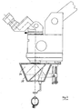
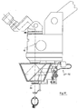
- an eyepiece 1 which is pivotable about an axis 2, so that, for example in an eye operation, the surgeon can optimally adjust the eyepiece 1 of his posture during surgery. Furthermore, an adjustment 3 for changing the magnification scale is provided on the microscope.
- An objective 4 initially allows observation of the front portion of the eye 5 on an eye 6.
- an optical system 8 for observation of the fundus 9 is supported, which can be pivoted into the beam path 10 of the microscope and by means of a (first) Spindle drive 11 in the direction of the beam path 10 is movable.
- This optics 8 here a simple observation lens, is attached to a holder 12, which is pivotable about a swivel pin 13 fixed to the projection 7.
- the optics 8 is attached to a (first) traverse 14, which is guided on a guide pin 15 parallel to the beam path 10 below the lens 4 movable.
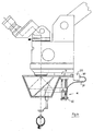
- the cross member 14 is moved by a driver, not shown, which engages in the threaded spindle 17.
- the guide pin 15 and the threaded spindle 17 are on the one hand in a common, locked to the holder 12 bearing piece 18 and on the other hand in a (first) connecting plate 19 attached.
- the threaded spindle 17 is rotatably mounted about its axis.
- a (first) knob 20 is provided, with the aid of the spindle output 11 can be set in motion and the optics 8 along the beam path 10 is movable.
- the optics 8 is attached to the retaining bolt 22, which is resiliently held in a guide 21.
- the complete spindle drive is separable from the holder 12 on the bearing piece 18 so that it can be sterilized.
- An image reversion and alignment device 23 connected to the optic 8 through the common holder 12 consists of a porro prism system 2 of the type 24 and a housing 25 accommodating the prism system 24; the housing 25 may be formed integrally with the holder 12 and the bearing piece 18.
- the bearing piece 18 is detachably formed by the holder 12.
- the prism system 24 Depending on an opening 26,27 in the housing 25 allow the passage of the beam path 10 through the prism system 24.
- the input of the beam path 10 in the prism system 24 is connected in the lens 4 adjacent opening 26 an imaging optics 28 for adjusting the due to the prism system 24th considerably extended beam path 10.
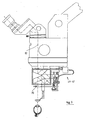
- the spindle drive 11 is equipped with an electric motor drive.
- an electric motor 29 is provided on the projection 7, from the output of a connectable by means of a suitable coupling 30 flexible shaft 31 and a belt drive 32, the threaded spindle 17 can be rotated.
- the electric motor can also be mounted elsewhere in the system. It is therefore sufficient to switch the electric motor 29 from a foot switch to move the optics 8 along the beam path 10; For example, a surgeon can focus accordingly, without putting his surgical instruments out of his hands and thus having to interrupt the ongoing operation.
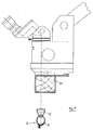
- One way to focus the optics 8, without having to move at all, according to the invention provides a longitudinally along the beam path 10 movable optics 34 for adapting the intermediate image accordingly Fig.7-10 ,
- a (second) spindle drive 35 is installed for the optics 34, in this case a simple lens, one each further guide pin 36 and one threaded spindle 37 on the side remote from the first spindle drive 11 attached to the first connecting plate 19 and held together at its other end by a (second) connecting strap 38.
- the optic 34 is supported in a (second) cross member 39, which is just like the first cross member 14 contains a driver, which is moved by the rotating threaded spindle 37 in the direction of the beam path 10 when a corresponding, on the threaded spindle 37 held (second) knob 40 is actuated ( Figure 7 . 8th ).
- the spindle drive 35 but also according Figure 9 . 10 in a similar manner as the spindle drive 11 means of the electric drive 29-32 are operated.
- Fig. 14 shows the beam path below the microscope, this beam path through the use of four prisms, like them Fig. 15 . 16 show, has been improved. In particular, this results in an enlargement of the stereoscopic basis, which also eliminates aberrations. The advantage of this arrangement is that shading can not occur, thus ensuring better stereoscopic vision.
- the prisms used are equally strong, wherein the base of the underlying prisms 40 and 41 is trimmed to each other, while the closest to the lens 4 prisms 42 and 43 have their base directed outward. The drawn with the arrow B stereoscopic width is thereby significantly improved.
- the prisms have, for example, with a lens focal length of 200 mm, advantageously 5 pdpt (prismendioptrin).
- the same prisms 40 to 43 are arranged below or above the prism system 24, wherein in each case a converging lens 44, 45 or a diverging lens 46 or 47 are respectively arranged between the prisms 40, 41 and 42, 43.
- a converging lens 44, 45 or a diverging lens 46 or 47 are respectively arranged between the prisms 40, 41 and 42, 43.
Landscapes
- Physics & Mathematics (AREA)
- Health & Medical Sciences (AREA)
- Life Sciences & Earth Sciences (AREA)
- Optics & Photonics (AREA)
- General Health & Medical Sciences (AREA)
- Surgery (AREA)
- General Physics & Mathematics (AREA)
- Ophthalmology & Optometry (AREA)
- Medical Informatics (AREA)
- Biophysics (AREA)
- Chemical & Material Sciences (AREA)
- Engineering & Computer Science (AREA)
- Biomedical Technology (AREA)
- Heart & Thoracic Surgery (AREA)
- Analytical Chemistry (AREA)
- Molecular Biology (AREA)
- Animal Behavior & Ethology (AREA)
- Public Health (AREA)
- Veterinary Medicine (AREA)
- Microscoopes, Condenser (AREA)
- Eye Examination Apparatus (AREA)
Claims (18)
- Microscope pour l'observation sous grand angle d'un oeil (6), avec une optique (8, 33), située entre l'objectif (4) et l'oeil (6) à traiter, projetant une image à côtés renversés, pour l'observation du fond d'oeil (9), notamment pour des opérations de l'oeil et avec un dispositif (23) insérable et pivotant, situé dans la trajectoire du faisceau (10) du microscope, pour renverser et redresser l'image, le dispositif (23) pour renverser et pour redresser l'image consistant dans un système réfléchissant de faible hauteur, un système de prismes (24) qui est porté par un support (12) fixé sur le microscope, pour être insérable et pivotant de cette manière dans la trajectoire du faisceau (10) du microscope, entre l'objectif (4) et l'oeil (6) à traiter, en ce que le système de prismes (24) se trouve directement à l'avant de l'objectif (4), à une distance par rapport à l' oeil (6), alors qu'il est prévu toutefois, entre le système de prismes (24) et l'objectif (4) une optique de reproduction (28) directement voisine de l'objectif (4) après insertion ou pivotement du système de prismes (24) dans la trajectoire du faisceau (10) du microscope, pour l'adaptation de la trajectoire du faisceau (10),
caractérisé en ce que,
dans la trajectoire du faisceau (10), entre l'optique (8) pour observer le fond d'oeil (9) et le système de prismes (24), il est prévu une optique mobile le long de la trajectoire du faisceau (10) et par rapport au système de prismes (24), de sorte que l'optique (8) puisse être focalisée, sans être déplacée. - Procédé selon la revendication 1,
caractérisé en ce que,
l'optique (8) pour l'observation du fond d'oeil (9) est montée sur le support (12). - Microscope selon l'une quelconque des revendications 1 ou 2,
caractérisé en ce que,
le support (12) est rotatif autour d'un axe de pivotement (13) disposé sur le microscope, sur la face inférieure de ce dernier, ou est susceptible de se déplacer dans un guidage. - Microscope selon l'une quelconque des revendications 1 à 3,
caractérisé en ce que,
le système de prismes (24) est disposé dans un boîtier (25) fermé, qui est muni de jours (26, 27) pour la trajectoire du faisceau (10). - Procédé selon la revendication 3,
caractérisé en ce que,
l'axe de pivotement (13) est prévu à peu près à l'horizontale ou à la verticale sur le microscope. - Microscope selon l'une quelconque des revendications 1 à 5,
caractérisé en ce que,
l'optique (8) pour l'observation du fond d'oeil (9) est consiste dans un système de lentilles (10) disposé de façon mobile le long de la trajectoire du faisceau. - Microscope selon l'une quelconque des revendications 1 à 6,
caractérisé en ce que,
les optiques (8, 34) pour l'observation sous grand angle et/ou pour la représentation intermédiaire sont susceptibles d'être manoeuvrées au moyen d'actionneurs à broche à vis (11, 35 ; 29 à 32). - Microscope selon l'une quelconque des revendications 1 à 7,
caractérisé en ce que,
un système de prismes de Porro de 2ème type ou un prisme à réflexion selon Uppendahl sert de système de prismes (24). - Microscope selon l'une quelconque des revendications 1 à 7,
caractérisé en ce que,
un prisme à réflexion selon Schmidt Pechan sert de système de prismes (24). - Microscope selon l'une quelconque des revendications 1 à 9,
caractérisé en ce que,
le support (12) est mobile le long de la trajectoire du faisceau (10) au moyen d'un premier actionneur à broche à vis (11). - Procédé selon la revendication 10,
caractérisé en ce que,
l'optique (8) est fixée sur une traverse (14) qui est guidée en déplacement longitudinal sur une tige de guidage (15) montée sur le support (12) et s'étendant à la parallèle par rapport au premier actionneur à broche à vis (11), un premier bouton rotatif (20) pour le premier actionneur à broche à vis (11) étant logé sur la broche à vis (17). - Procédé selon la revendication 11,
caractérisé en ce que,
l'optique (34) pour l'adaptation de l'observation intermédiaire est mobile le long de la trajectoire du faisceau (10) au moyen d'un deuxième actionneur à broche à vis (35) fixé sur la tige de guidage (15), la première tige de guidage (15) étant reliée par l'intermédiaire d'une patte de liaison (19) avec la deuxième tige de guidage (36) et en ce qu'il est prévu un deuxième bouton rotatif (40) pour l'entraînement du deuxième actionneur à broche à vis (35). - Procédé selon la revendication 11 ou 12,
caractérisé en ce que,
les boutons rotatifs (20, 40) sont à actionnement manuel. - Procédé selon la revendication 11 ou 12,
caractérisé en ce que,
au moins l'un des boutons rotatifs (20, 40) est actionnable au moyen d'un entraînement électrique (29 à 32) . - Procédé selon la revendication 14,
caractérisé en ce que,
l'entraînement (29-32) comporte un moteur électrique (29) se situant de préférence sur le support (12), dont la réduction est susceptible d'être couplée en rotation avec le bouton rotatif (20, 40) par l'intermédiaire d'un arbre flexible (31). - Microscope selon l'une quelconque des revendications 1 à 15,
caractérisé en ce que,
le système de prismes (24) consiste dans deux unités de renversement et de redressement de l'image. - Microscope selon l'une quelconque des revendications 1 à 16,
caractérisé en ce que,
à l'avant et à l'arrière de chaque système de prismes (24) sont disposés chaque fois deux prismes (40 à 43) sensiblement situés dans un plan, couvrant la trajectoire du faisceau, en ce que la base de prisme des prismes respectifs (40 à 43) situés sensiblement dans un plan sont disposées à l'opposée, en ce que la base de prisme des prismes (42, 43) les plus proches de l'objectif sont chaque fois opposées et en ce que celle des autres prismes (40, 41) se font face. - Procédé selon la revendication 17,
caractérisé en ce que,
entre chaque prisme (40 à 43) et le système de prismes (24) est disposée une lentille convexe ou lentille divergente (44 à 47) et en ce que les lentilles divergentes (46, 47) sont voisines de l'objectif (4) du microscope.
Applications Claiming Priority (2)
| Application Number | Priority Date | Filing Date | Title |
|---|---|---|---|
| DE20021955U | 2000-12-23 | ||
| DE20021955U DE20021955U1 (de) | 2000-12-23 | 2000-12-23 | Mikroskop zur Weitwinkelbeobachtung, insbesondere für Augenoperationen |
Publications (4)
| Publication Number | Publication Date |
|---|---|
| EP1227355A2 EP1227355A2 (fr) | 2002-07-31 |
| EP1227355A3 EP1227355A3 (fr) | 2003-11-12 |
| EP1227355B1 true EP1227355B1 (fr) | 2008-06-11 |
| EP1227355B2 EP1227355B2 (fr) | 2011-07-27 |
Family
ID=7950607
Family Applications (1)
| Application Number | Title | Priority Date | Filing Date |
|---|---|---|---|
| EP01121232A Expired - Lifetime EP1227355B2 (fr) | 2000-12-23 | 2001-09-05 | Microscope pour observation à grand angle, notamment de chirurgie ophthalmologique |
Country Status (5)
| Country | Link |
|---|---|
| US (2) | US6788455B2 (fr) |
| EP (1) | EP1227355B2 (fr) |
| JP (1) | JP4154148B2 (fr) |
| DE (2) | DE20021955U1 (fr) |
| ES (1) | ES2307560T5 (fr) |
Cited By (3)
| Publication number | Priority date | Publication date | Assignee | Title |
|---|---|---|---|---|
| EP2244118A1 (fr) | 2009-04-20 | 2010-10-27 | Dieter Mann GmbH | Fixation d'adaptateur pour microscope d'opération |
| DE102013219379B3 (de) * | 2013-09-26 | 2015-03-12 | Carl Zeiss Meditec Ag | Optisches Abbildungssystem |
| DE102013219383B3 (de) * | 2013-09-26 | 2015-03-12 | Carl Zeiss Meditec Ag | Optisches Abbildungssystem |
Families Citing this family (25)
| Publication number | Priority date | Publication date | Assignee | Title |
|---|---|---|---|---|
| DE10140402B4 (de) * | 2000-09-26 | 2012-08-30 | Carl Zeiss Meditec Ag | Bildumkehrsystem, Ophthalmoskopie-Vorsatzmodul und Operationsmikroskop |
| WO2002027379A2 (fr) * | 2000-09-26 | 2002-04-04 | Carl Zeiss | Systeme de redressement de l'image, module d'ophtalmoscopie additionnel et microscope d'operation |
| DE20021955U1 (de) † | 2000-12-23 | 2001-03-15 | Oculus Optikgeräte GmbH, 35582 Wetzlar | Mikroskop zur Weitwinkelbeobachtung, insbesondere für Augenoperationen |
| JP4068371B2 (ja) * | 2001-06-13 | 2008-03-26 | 株式会社トプコン | 手術用顕微鏡 |
| CN1327263C (zh) * | 2002-03-26 | 2007-07-18 | 株式会社拓普康 | 手术用显微镜 |
| DE20215635U1 (de) * | 2002-10-11 | 2002-12-05 | Oculus Optikgeräte GmbH, 35582 Wetzlar | Optische Vorrichtung zur lösbaren Befestigung an einem Mikroskop |
| JP4224317B2 (ja) * | 2003-01-30 | 2009-02-12 | 株式会社トプコン | 手術用顕微鏡支持装置 |
| JP4417036B2 (ja) * | 2003-06-09 | 2010-02-17 | 株式会社トプコン | 眼科用手術顕微鏡 |
| DE10332603B4 (de) * | 2003-07-17 | 2006-04-06 | Leica Microsystems (Schweiz) Ag | Stereomikroskop |
| JP2005034285A (ja) * | 2003-07-18 | 2005-02-10 | Topcon Corp | 手術用顕微鏡及び観察プリズム |
| DE102004050893B4 (de) * | 2003-10-31 | 2015-05-21 | Carl Zeiss Meditec Ag | Tubus mit zwei umschaltbaren Planoptikelementen zur wahlweisen Strahlengangvertauschung und Bildumkehr für ein Mikroskop sowie Mikroskop |
| DE102004043998A1 (de) * | 2004-09-11 | 2006-03-16 | Carl Zeiss Meditec Ag | Ophthalmologisches Gerät, insbesondere Spaltlampe, mit Stereobasis-Wechselvorrichtung |
| DE102005040834A1 (de) * | 2005-08-25 | 2007-03-08 | Carl Zeiss Jena Gmbh | Einrichtung zum Wechseln von Objektiven an optischen Geräten, insbesondere an Mikroskopen |
| GB0608258D0 (en) | 2006-04-26 | 2006-06-07 | Perkinelmer Singapore Pte Ltd | Spectroscopy using attenuated total internal reflectance (ATR) |
| US7903331B2 (en) * | 2006-07-31 | 2011-03-08 | Volk Optical, Inc. | Flexible positioner and ophthalmic microscope incorporating the same |
| DE102006047459A1 (de) * | 2006-10-07 | 2008-04-10 | Carl Zeiss Surgical Gmbh | Ophthalmo-Operationsmikroskopsystem |
| US7940479B2 (en) * | 2007-04-02 | 2011-05-10 | Volk Optical, Inc. | Positioners and microscopes incorporating the same |
| JP5030669B2 (ja) * | 2007-05-31 | 2012-09-19 | 興和株式会社 | レンズ支持装置、眼底画像取得装置、及び眼底画像取得システム |
| DE102008011608A1 (de) * | 2008-02-28 | 2009-09-03 | Carl Zeiss Surgical Gmbh | Vorsatzeinrichtung für eine optische Beobachtungseinrichtung |
| JP2010000110A (ja) * | 2008-06-18 | 2010-01-07 | Topcon Corp | 二眼式ステレオビデオ顕微鏡装置 |
| DE202009014603U1 (de) * | 2009-10-29 | 2011-03-10 | Möller-Wedel GmbH | Modul zur stereoskopischen Weitwinkel-Fundusbeobachtung für ein ophthalmologisches Operationsmikroskop |
| DE102011007607B3 (de) | 2011-04-18 | 2012-08-02 | Leica Microsystems (Schweiz) Ag | Operationsmikroskopsystem |
| EP2921099A1 (fr) | 2014-03-18 | 2015-09-23 | Dieter Mann GmbH | Adaptateur d'ophtalmoscopie pour microscope opératoire |
| DE102017105580B4 (de) * | 2016-11-04 | 2025-10-02 | Carl Zeiss Meditec Ag | Operationsmikroskop |
| CN110068920A (zh) * | 2019-05-29 | 2019-07-30 | 苏州四海通仪器有限公司 | 一种用于显微镜的非接触广角倒像装置及显微镜系统 |
Family Cites Families (22)
| Publication number | Priority date | Publication date | Assignee | Title |
|---|---|---|---|---|
| US4015898A (en) * | 1975-04-14 | 1977-04-05 | Kurt Ernest Schirmer | Upright wide angle stereo ophthalmoscope |
| DE3215566A1 (de) * | 1982-04-26 | 1983-10-27 | Ernst Leitz Wetzlar Gmbh, 6330 Wetzlar | Antrieb zur scharfstellung eines mikroskopes |
| DE3217776C2 (de) * | 1982-05-12 | 1985-01-31 | Fa. Carl Zeiss, 7920 Heidenheim | Stereomikroskop |
| DE3539009A1 (de) * | 1985-11-02 | 1987-05-07 | Moeller J D Optik | Vorsatz fuer ein stereoskopisches operationsmikroskop fuer die augenchirurgie |
| DE3826069C2 (de) † | 1988-07-30 | 1997-04-24 | Oculus Optikgeraete Gmbh | Prismensystem für ein ophthalmoskopisches Stereomikroskop |
| DE8902035U1 (de) * | 1989-02-21 | 1989-03-30 | J.D. Möller Optische Werke GmbH, 2000 Wedel | Stereoskopisches Operationsmikroskop |
| US5200773A (en) * | 1989-10-27 | 1993-04-06 | Volk Donald A | Diagnostic indirect ophthalmoscopy contact lens system |
| BE1003017A4 (nl) * | 1990-03-29 | 1991-10-22 | K U Leuven Res & Dev Vzw | Inrichting voor het observeren van het oog omvattende middelen voor het omkeren van het beeld. |
| US5438456A (en) * | 1991-03-14 | 1995-08-01 | Grinblat; Avi | Optical stereoscopic microscope system |
| US5321447A (en) * | 1991-05-04 | 1994-06-14 | Carl-Zeiss-Stiftung | Ophthalmoscopic attachment for a surgical microscope |
| DE4116385A1 (de) * | 1991-05-18 | 1992-11-19 | Oculus Optikgeraete Gmbh | Stereoskopisches mikroskop |
| DE9415219U1 (de) * | 1994-09-22 | 1994-11-24 | Oculus Optikgeräte GmbH, 35582 Wetzlar | Vorsatzeinrichtung für ein Mikroskop |
| US5526074A (en) * | 1994-10-31 | 1996-06-11 | Volk; Donald A. | Full field reinverting indirect contact ophthalmoscope |
| DE19541237B4 (de) * | 1994-11-12 | 2006-04-13 | Carl Zeiss | Pankratisches Vergrößerungssystem |
| DE19524475C1 (de) * | 1995-07-10 | 1996-11-14 | Fraunhofer Ges Forschung | Optische Zentriervorrichtung zum lagegenauen Bestücken eines Bauelements in Oberflächenmontagetechnik sowie deren Verwendung zur Montage von Laserdioden |
| US5986801A (en) † | 1996-11-08 | 1999-11-16 | Volk; Donald A. | Image reinverter for stereo microscope |
| US5793524A (en) * | 1997-08-04 | 1998-08-11 | Luloh; K. Peter | Device for non-contact wide-angle viewing of fundus during vitrectomy |
| DE29905969U1 (de) * | 1999-04-08 | 1999-07-08 | Oculus Optikgeräte GmbH, 35582 Wetzlar | Stereoskopisches Mikroskop |
| DE10140402B4 (de) * | 2000-09-26 | 2012-08-30 | Carl Zeiss Meditec Ag | Bildumkehrsystem, Ophthalmoskopie-Vorsatzmodul und Operationsmikroskop |
| WO2002027379A2 (fr) † | 2000-09-26 | 2002-04-04 | Carl Zeiss | Systeme de redressement de l'image, module d'ophtalmoscopie additionnel et microscope d'operation |
| DE20017891U1 (de) * | 2000-10-18 | 2001-02-08 | Oculus Optikgeräte GmbH, 35582 Wetzlar | Mikroskop zur kontaktfreien Weitwinkel-Beobachtung |
| DE20021955U1 (de) * | 2000-12-23 | 2001-03-15 | Oculus Optikgeräte GmbH, 35582 Wetzlar | Mikroskop zur Weitwinkelbeobachtung, insbesondere für Augenoperationen |
-
2000
- 2000-12-23 DE DE20021955U patent/DE20021955U1/de not_active Expired - Lifetime
-
2001
- 2001-09-05 EP EP01121232A patent/EP1227355B2/fr not_active Expired - Lifetime
- 2001-09-05 ES ES01121232T patent/ES2307560T5/es not_active Expired - Lifetime
- 2001-09-05 DE DE50114022T patent/DE50114022D1/de not_active Expired - Lifetime
- 2001-12-17 US US10/023,783 patent/US6788455B2/en not_active Expired - Lifetime
- 2001-12-20 JP JP2001388087A patent/JP4154148B2/ja not_active Expired - Lifetime
-
2004
- 2004-06-01 US US10/858,413 patent/US6967774B2/en not_active Expired - Lifetime
Cited By (7)
| Publication number | Priority date | Publication date | Assignee | Title |
|---|---|---|---|---|
| EP2244118A1 (fr) | 2009-04-20 | 2010-10-27 | Dieter Mann GmbH | Fixation d'adaptateur pour microscope d'opération |
| DE102009018114A1 (de) | 2009-04-20 | 2011-01-05 | Dieter Mann Gmbh | Weitwinkelbeobachtung am Operationsmikroskop |
| US8272737B2 (en) | 2009-04-20 | 2012-09-25 | Dieter Mann Gmbh | Wide-angle observation at a surgical microscope |
| DE102013219379B3 (de) * | 2013-09-26 | 2015-03-12 | Carl Zeiss Meditec Ag | Optisches Abbildungssystem |
| DE102013219383B3 (de) * | 2013-09-26 | 2015-03-12 | Carl Zeiss Meditec Ag | Optisches Abbildungssystem |
| EP2853934A1 (fr) | 2013-09-26 | 2015-04-01 | Carl Zeiss Meditec AG | Système d'imagerie optique |
| EP2853933A1 (fr) | 2013-09-26 | 2015-04-01 | Carl Zeiss Meditec AG | Système d'imagerie optique |
Also Published As
| Publication number | Publication date |
|---|---|
| EP1227355B2 (fr) | 2011-07-27 |
| EP1227355A3 (fr) | 2003-11-12 |
| EP1227355A2 (fr) | 2002-07-31 |
| DE50114022D1 (de) | 2008-07-24 |
| DE20021955U1 (de) | 2001-03-15 |
| US20040218266A1 (en) | 2004-11-04 |
| ES2307560T3 (es) | 2008-12-01 |
| US6788455B2 (en) | 2004-09-07 |
| ES2307560T5 (es) | 2011-11-16 |
| US20020118448A1 (en) | 2002-08-29 |
| JP4154148B2 (ja) | 2008-09-24 |
| US6967774B2 (en) | 2005-11-22 |
| JP2002253575A (ja) | 2002-09-10 |
Similar Documents
| Publication | Publication Date | Title |
|---|---|---|
| EP1227355B1 (fr) | Microscope pour observation à grand angle, notamment de chirurgie ophthalmologique | |
| EP1326117B2 (fr) | Adaptateur ophtalmoscopique et microscope chirurgical | |
| DE10262323B4 (de) | Operationsmikroskop | |
| DE69016139T2 (de) | Mikroskop/Endoskop-Vorrichtung, insbesondere zur Verwendung in der Chirurgie. | |
| DE4233274B4 (de) | Optisches Augenbehandlungsgerät | |
| DE4321934C2 (de) | Chirurgische Mikroskopapparatur | |
| DE102004050893B4 (de) | Tubus mit zwei umschaltbaren Planoptikelementen zur wahlweisen Strahlengangvertauschung und Bildumkehr für ein Mikroskop sowie Mikroskop | |
| DE3105018A1 (de) | Operationsmikroskop | |
| EP1199591B1 (fr) | Microscope pour observation à grand angle sans contact | |
| DE102009018114A1 (de) | Weitwinkelbeobachtung am Operationsmikroskop | |
| EP0193818A1 (fr) | Stéréomicroscope pour opérations | |
| WO2010127827A1 (fr) | Objectif à deux directions de visée destiné à un endoscope | |
| EP1320779B1 (fr) | Systeme de redressement de l'image, module d'ophtalmoscopie additionnel et microscope d'operation | |
| EP3058413B1 (fr) | Microscope opératoire muni d'interfaces optiques | |
| EP0167926A1 (fr) | Microscope comportant un tube binoculaire | |
| CH687424A5 (de) | Operationsmikroskop. | |
| EP2316330B1 (fr) | Module d'observation ophtalmoscopique à grand angle stéréoscopique pour un microscope d'opération ophtalmologique | |
| EP3851897B1 (fr) | Instrument optique d'observation | |
| DE3888911T3 (de) | Binokulares Mikroskop. | |
| DE29905970U1 (de) | Vorrichtung zur Betrachtung des Augenhintergrundes | |
| CH687790A5 (de) | Zusatzmodul fuer ein Stereomikroskop. | |
| DE102006038911A1 (de) | Ophthalmoskopie-Vorsatzmodul und Operationsmikroskop mit Ophthalmoskopie-Vorsatzzmodul | |
| DE19503575B4 (de) | Binokulartubus für ein Stereomikroskop | |
| EP2090913A2 (fr) | Tubes pour un dispositif d'observation | |
| EP1410754B1 (fr) | Microscope chirurgical à dispositif d'illumination |
Legal Events
| Date | Code | Title | Description |
|---|---|---|---|
| PUAI | Public reference made under article 153(3) epc to a published international application that has entered the european phase |
Free format text: ORIGINAL CODE: 0009012 |
|
| AK | Designated contracting states |
Kind code of ref document: A2 Designated state(s): AT BE CH CY DE DK ES FI FR GB GR IE IT LI LU MC NL PT SE TR |
|
| AX | Request for extension of the european patent |
Free format text: AL;LT;LV;MK;RO;SI |
|
| PUAL | Search report despatched |
Free format text: ORIGINAL CODE: 0009013 |
|
| AK | Designated contracting states |
Kind code of ref document: A3 Designated state(s): AT BE CH CY DE DK ES FI FR GB GR IE IT LI LU MC NL PT SE TR |
|
| AX | Request for extension of the european patent |
Extension state: AL LT LV MK RO SI |
|
| RIC1 | Information provided on ipc code assigned before grant |
Ipc: 7A 61B 3/13 B Ipc: 7G 02B 21/00 A |
|
| 17P | Request for examination filed |
Effective date: 20040115 |
|
| AKX | Designation fees paid |
Designated state(s): DE ES FR GB |
|
| 17Q | First examination report despatched |
Effective date: 20070608 |
|
| GRAP | Despatch of communication of intention to grant a patent |
Free format text: ORIGINAL CODE: EPIDOSNIGR1 |
|
| GRAS | Grant fee paid |
Free format text: ORIGINAL CODE: EPIDOSNIGR3 |
|
| GRAA | (expected) grant |
Free format text: ORIGINAL CODE: 0009210 |
|
| AK | Designated contracting states |
Kind code of ref document: B1 Designated state(s): DE ES FR GB |
|
| REG | Reference to a national code |
Ref country code: GB Ref legal event code: FG4D Free format text: NOT ENGLISH |
|
| REF | Corresponds to: |
Ref document number: 50114022 Country of ref document: DE Date of ref document: 20080724 Kind code of ref document: P |
|
| REG | Reference to a national code |
Ref country code: ES Ref legal event code: FG2A Ref document number: 2307560 Country of ref document: ES Kind code of ref document: T3 |
|
| PLBI | Opposition filed |
Free format text: ORIGINAL CODE: 0009260 |
|
| PLAX | Notice of opposition and request to file observation + time limit sent |
Free format text: ORIGINAL CODE: EPIDOSNOBS2 |
|
| 26 | Opposition filed |
Opponent name: CARL ZEISS SURGICAL GMBH Effective date: 20090311 |
|
| PLAB | Opposition data, opponent's data or that of the opponent's representative modified |
Free format text: ORIGINAL CODE: 0009299OPPO |
|
| PLBB | Reply of patent proprietor to notice(s) of opposition received |
Free format text: ORIGINAL CODE: EPIDOSNOBS3 |
|
| PUAH | Patent maintained in amended form |
Free format text: ORIGINAL CODE: 0009272 |
|
| STAA | Information on the status of an ep patent application or granted ep patent |
Free format text: STATUS: PATENT MAINTAINED AS AMENDED |
|
| 27A | Patent maintained in amended form |
Effective date: 20110727 |
|
| AK | Designated contracting states |
Kind code of ref document: B2 Designated state(s): DE ES FR GB |
|
| REG | Reference to a national code |
Ref country code: DE Ref legal event code: R102 Ref document number: 50114022 Country of ref document: DE |
|
| REG | Reference to a national code |
Ref country code: DE Ref legal event code: R102 Ref document number: 50114022 Country of ref document: DE Effective date: 20110727 |
|
| REG | Reference to a national code |
Ref country code: ES Ref legal event code: DC2A Ref document number: 2307560 Country of ref document: ES Kind code of ref document: T5 Effective date: 20111116 |
|
| REG | Reference to a national code |
Ref country code: FR Ref legal event code: PLFP Year of fee payment: 16 |
|
| REG | Reference to a national code |
Ref country code: FR Ref legal event code: PLFP Year of fee payment: 17 |
|
| REG | Reference to a national code |
Ref country code: FR Ref legal event code: PLFP Year of fee payment: 18 |
|
| PGFP | Annual fee paid to national office [announced via postgrant information from national office to epo] |
Ref country code: GB Payment date: 20200923 Year of fee payment: 20 Ref country code: FR Payment date: 20200922 Year of fee payment: 20 |
|
| PGFP | Annual fee paid to national office [announced via postgrant information from national office to epo] |
Ref country code: ES Payment date: 20201016 Year of fee payment: 20 Ref country code: DE Payment date: 20201127 Year of fee payment: 20 |
|
| REG | Reference to a national code |
Ref country code: DE Ref legal event code: R071 Ref document number: 50114022 Country of ref document: DE |
|
| REG | Reference to a national code |
Ref country code: GB Ref legal event code: PE20 Expiry date: 20210904 |
|
| PG25 | Lapsed in a contracting state [announced via postgrant information from national office to epo] |
Ref country code: GB Free format text: LAPSE BECAUSE OF EXPIRATION OF PROTECTION Effective date: 20210904 |
|
| REG | Reference to a national code |
Ref country code: ES Ref legal event code: FD2A Effective date: 20220126 |
|
| PG25 | Lapsed in a contracting state [announced via postgrant information from national office to epo] |
Ref country code: ES Free format text: LAPSE BECAUSE OF EXPIRATION OF PROTECTION Effective date: 20210906 |