EP1227566A2 - Klauenpolgenerator mit Permanentmagneten - Google Patents
Klauenpolgenerator mit Permanentmagneten Download PDFInfo
- Publication number
- EP1227566A2 EP1227566A2 EP01119779A EP01119779A EP1227566A2 EP 1227566 A2 EP1227566 A2 EP 1227566A2 EP 01119779 A EP01119779 A EP 01119779A EP 01119779 A EP01119779 A EP 01119779A EP 1227566 A2 EP1227566 A2 EP 1227566A2
- Authority
- EP
- European Patent Office
- Prior art keywords
- permanent magnet
- claws
- rotor
- claw
- magnetic pole
- Prior art date
- Legal status (The legal status is an assumption and is not a legal conclusion. Google has not performed a legal analysis and makes no representation as to the accuracy of the status listed.)
- Granted
Links
Images


Classifications
-
- H—ELECTRICITY
- H02—GENERATION; CONVERSION OR DISTRIBUTION OF ELECTRIC POWER
- H02K—DYNAMO-ELECTRIC MACHINES
- H02K21/00—Synchronous motors having permanent magnets; Synchronous generators having permanent magnets
- H02K21/02—Details
- H02K21/04—Windings on magnets for additional excitation ; Windings and magnets for additional excitation
-
- H—ELECTRICITY
- H02—GENERATION; CONVERSION OR DISTRIBUTION OF ELECTRIC POWER
- H02K—DYNAMO-ELECTRIC MACHINES
- H02K21/00—Synchronous motors having permanent magnets; Synchronous generators having permanent magnets
- H02K21/02—Details
- H02K21/04—Windings on magnets for additional excitation ; Windings and magnets for additional excitation
- H02K21/042—Windings on magnets for additional excitation ; Windings and magnets for additional excitation with permanent magnets and field winding both rotating
- H02K21/044—Rotor of the claw pole type
-
- H—ELECTRICITY
- H02—GENERATION; CONVERSION OR DISTRIBUTION OF ELECTRIC POWER
- H02K—DYNAMO-ELECTRIC MACHINES
- H02K1/00—Details of the magnetic circuit
- H02K1/06—Details of the magnetic circuit characterised by the shape, form or construction
- H02K1/22—Rotating parts of the magnetic circuit
- H02K1/27—Rotor cores with permanent magnets
Definitions
- the present invention relates to a vehicular alternator, and more particularly to a vehicular alternator including a permanent magnet for auxiliary excitation.
- a vehicular alternator usually comprises a rotor and a stator.
- the rotor comprises a pair of claw-type magnetic poles arranged in an opposed relation, and field windings coiled radially inward of a plurality of claws provided in each of the claw-type magnetic poles.
- the stator is constituted by coiling stator windings, from which an AC induced voltage is outputted, over a stator core. The rotor is rotated relative to the stator.
- a magnetic circuit is formed in which the magnetic flux outgoing from the claw-type magnetic pole magnetized to an N pole returns to the claw-type magnetic pole magnetized to an S pole through the stator windings.
- the magnetic flux of the magnetic circuit is in an interlinkage relation to the stator windings of the stator, while the rotor rotates relative to the stator. As a result, an AC induced voltage is generated in the stator windings.
- JP,A 11-318064 discloses such a vehicular alternator including a permanent magnet for auxiliary excitation disposed between the claw-type magnetic poles.
- claws of a claw-type magnetic pole are each formed into a substantially triangular shape in section taken along the axial direction of a rotor such that the claw is tapered toward its tip, for the purpose of reducing the weight of a claw end portion.
- the claws of the claw-type magnetic pole are cantilevered.
- such a sectional shape is intended to prevent the claw end portion from rising radially outward of the rotor due to centrifugal forces when the rotor rotates at high speeds.
- each claw is likewise formed into a substantially triangular shape in section taken along the axial direction of the rotor such that the claw is tapered toward its tip.
- the related art employs a permanent magnet having a relatively small thickness in the radial direction of the rotor, a particular consideration is not focused on the shape of a contact surface between the claw and the permanent magnet. Hence, a part of a magnetic pole surface of the permanent magnet not contacting the claw also occurs near a claw end portion, and effective utilization of the magnetic flux of the permanent magnet is not ensured.
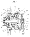
- Fig. 1 is a sectional view showing an overall structure of a first embodiment of a vehicular alternator according to the present invention.
- the vehicular alternator of this embodiment mainly comprises a rotor 1 and a stator 2.
- the rotor 1 comprises a shaft (rotary shaft) 3; a yoke 4 having the center of rotation through which the shaft 3 is inserted; a pair of claw-type magnetic poles 5A, 5B each made of a magnetic substance and having the center of rotation through which the shaft 3 is inserted, the claw-type magnetic poles 5A, 5B being arranged in an opposed relation through the yoke 4 with a predetermined spacing held between them in the axial direction of the rotor 1 (left-and-right direction in Fig. 1); and field windings 6 coiled over the yoke 4.
- the claw-type magnetic poles 5A, 5B are provided with a plurality of claws 5Aa, 5Ba, respectively. Looking in the circumferential direction of the rotor 1, as shown in Fig. 1, the claws 5Aa, 5Ba are disposed to project alternately in the axial direction of the rotor 1 (left-and-right direction in Fig. 1) in an overlapped relation.
- a permanent magnet 7 for auxiliary excitation is interposed between two adjacent claws 5Aa, 5Ba in the circumferential direction of the rotor 1.
- the field windings 6 coiled over the yoke 4 are positioned inward of the claws 5Aa, 5Ba in the radial direction of the rotor 1 with a predetermined space gap left therebetween.
- the shaft 3 is rotatably supported with respect to an alternator body, which comprises end brackets 8A, 8B, by a bearing 9A at a position near an end on one side (left side in Fig. 1) and a bearing 9B at a position near an end on the other side (right side in Fig. 1).
- a pulley 10 is fixed by a bolt 11 to the end of the shaft 3 on one side (left side in Fig. 1), and slip rings 12a, 12b are provided near the end of the shaft 3 on the other side (right side in Fig. 1).
- the pulley 10 is coupled by a belt or the like to, for example, a crank pulley of an engine (not shown).
- brushes 13a, 13b are provided in slide contact with outer circumferences of the slip rings 12a, 12b.
- a current is supplied to the field windings 6 of the rotor 1 during rotation thereof through the brushes 13a, 13b and the slip rings 12a, 12b.
- the claw-type magnetic pole 5A of the rotor 1 is magnetized to an S pole and the claw-type magnetic pole 5B is magnetized to an N pole.
- the stator 2 comprises a stator core 14 sandwiched between the end brackets 8A, 8B and positioned outward of the claws 5Aa, 5Ba in the radial direction of the rotor 1 (on the upper and lower sides in Fig. 1) with small gaps left relative to the claws 5Aa, 5Ba; and three-phase stator windings 15 coiled over the stator core 14 for outputting an AC induced voltage from them.
- the rotor 1 is rotated relative to the stator 2.
- a magnetic circuit is formed in which the magnetic flux outgoing from the claw-type magnetic pole 5B magnetized to an N pole returns to the claw-type magnetic pole 5A magnetized to an S pole through the stator core 14.
- the magnetic flux of the magnetic circuit is in an interlinkage relation to the stator windings 15, while the rotor 1 rotates relative to the stator 2.
- an AC induced voltage is generated in the stator windings 15.
- a rectifying circuit 16 and a voltage adjuster 17 are provided inside the end bracket 8B.
- the rectifying circuit 16 has a battery terminal 18 connected to a positive electrode of a battery (not shown) and a grounding terminal 19 connected to a negative electrode of the battery (not shown).
- the rectifying circuit 16 rectifies the AC induced voltage, which is generated in the stator windings 15 as described above, for conversion into a DC voltage.
- the voltage adjuster 17 controls the current supplied to the field windings 6 depending on a load current and the number of revolutions of the rotor 1 so that the DC voltage rectified by the rectifying circuit 16 is kept at a constant voltage of, e.g., about 14.5 V, for thereby charging the battery (not shown).
- Cooling fans 20a, 20b for air-cooling the stator 2 and the rectifying circuit 16 are provided on both sides of the rotor 1 in the axial direction thereof (left-and-right direction in Fig. 1).
- the cooling fans 20a, 20b produces cooling air at a flow rate in proportion to the number of revolutions of the rotor 1.
- the most important feature of the present invention resides in that,the claws 5Aa, 5Ba of the rotor 1 are each formed to have a shape coming into contact with the whole of the lateral surface (i.e., magnetic pole surface) of the permanent magnet 7 in the circumferential direction of the rotor 1.
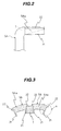
- Fig. 2 is a side view showing a detailed structure of the claw 5Aa
- Fig. 3 is a sectional view, taken along line III-III in Fig. 1, showing the positional relationship between the claws 5Aa, 5Ba and the permanent magnet 7.
- Fig. 3 shows only one pole constituted by each of the claws 5Aa, 5Ba.
- the claws 5Aa, 5Ba are each formed into a substantially triangular shape in section taken along the axial direction of the rotor 1 (left-and-right direction in Fig. 2), as indicated by dotted line in Fig. 2 similarly to the related art, such that the claw 5Aa, for example, is tapered toward its tip (to the right in Fig. 2), except for both lateral ends of each claw in the circumferential direction of the rotor 1.
- the permanent magnet 7 is formed to have substantially rectangular lateral surfaces (i.e., magnetic pole surfaces) in the circumferential direction of the rotor 1 (left-and-right direction in Fig. 3). Then, as described above, the permanent magnet 7 is interposed between the claws 5Aa, 5Ba overlapping with each other in the axial direction of the rotor 1 (left-and-right direction in Fig. 2).
- auxiliary magnetic pole portions 21 are provided at both the lateral ends of each of the claws 5Aa, 5Ba (end surfaces of the claws 5Aa, 5Ba facing each other in an overlapped relation) in the circumferential direction of the rotor 1 (left-and-right direction in Fig. 3) so as to project inward for contact with the whole of the magnetic pole surfaces of the permanent magnet 7.
- each auxiliary magnetic pole portion 21 is formed into substantially the same shape as the corresponding magnetic pole surface of the permanent magnet 7 so that the auxiliary magnetic pole portion 21 is brought into close contact with the permanent magnet 7.
- projecting flanges 22 are provided at both the lateral ends of each of the claws 5Aa, 5Ba in the circumferential direction of the rotor 1 (left-and-right direction in Fig. 3) so as to project circumferentially from outermost portions of both the lateral ends of each claw in the radial direction of the rotor 1 (upper side in Fig. 3).
- the flanges 22 serve to prevent the permanent magnet 7 from ejecting outward due to the rotation of the rotor 1.
- a current is supplied through the brushes 13a, 13b and the slip rings 12a, 12b to the field windings 6 of the rotor 1 that is rotated upon receiving motive power from, e.g., the engine (not shown).
- the claw-type magnetic pole 5A of the rotor 1 is magnetized to an S pole and the claw-type magnetic pole 5B is magnetized to an N pole.
- a magnetic circuit is thereby formed in which the magnetic flux outgoing from the claw-type magnetic pole 5B magnetized to an N pole returns to the claw-type magnetic pole 5A magnetized to an S pole through the stator core 14 in the stator 2.
- the magnetic flux of the magnetic circuit formed by the field windings 6 is intensified by addition of the magnetic flux of the permanent magnet 7 for auxiliary magnetization. Furthermore, the magnetic flux of the magnetic circuit is in an interlinkage relation to the stator windings 15. As a result, with the rotation of the rotor 1 an AC induced voltage is generated in the 3-phase stator windings 15 coiled over the stator core 14.
- the generated voltage is rectified by the rectifying circuit 16 for conversion into a DC voltage, and then finally charged in the battery (not shown).
- the voltage adjuster 17 controls the current supplied to the field windings 6 depending on a load current and the number of revolutions of the rotor 1 so that the generated voltage is kept at a constant voltage of, e.g., about 14.5 V.
- claws of a claw-type magnetic pole are each formed into a substantially triangular shape in section taken along the axial direction of a rotor such that the claw is tapered toward its tip. Therefore, when a permanent magnet having a relatively large thickness in the radial direction of the rotor is disposed between the adjacent claws of the claw-type magnetic poles, a part of each magnetic pole surface of the permanent magnet does not contact the claw. Thus, the resistance against a flow of magnetic flux (i.e., magnetic loss) in a magnetic circuit formed by the permanent magnet is increased and the magnetic flux of the permanent magnet is not effectively utilized.
- the claws 5Aa, 5Ba of the claw-type magnetic poles 5A, 5B are each formed to have a shape coming into contact with the whole of the magnetic pole surface of the permanent magnet 7 in the circumferential direction of the rotor 1, thereby enabling almost all of the magnetic flux outgoing from the permanent magnet 7 to flow into the claws 5Aa, 5Ba. It is hence possible to reduce the resistance against a flow of the magnetic flux (i.e., magnetic loss) in the magnetic circuit formed by the permanent magnet 7 and to effectively utilize the magnetic flux of the permanent magnet. As a result, the output of the vehicular alternator can be increased.
- the magnetic flux of the permanent magnet 7 can be effectively utilized and the output of the vehicular alternator can be increased because of the advantage of above (1). Consequently, the production cost of the vehicular alternator can be reduced.
- a neodymium magnet is employed as the permanent magnet for auxiliary excitation.
- the inflection point of an irreversible demagnetization characteristic of such a permanent magnet varies when temperature rises. If the permeance factor is low, therefore, the magnetic density may reduce at high temperatures (called demagnetization at high temperatures).
- demagnetization at high temperatures when the conventional claw-type magnetic pole is employed which has the claw not contacting the whole of the magnetic pole surface of the permanent magnet, the resistance against a flow of the magnetic flux is increased in the part of the magnetic pole surface of the permanent magnet not contacting the claw of the claw-type magnetic pole, and hence the permeance factor is partly lowered.
- a process of manufacturing the vehicular alternator generally comprises the steps of arranging each permanent magnet for auxiliary excitation, which is in a not yet magnetized state, between the adjacent claws of the claw-type magnetic poles, adjusting a balance in rotation of a rotor, and magnetizing the permanent magnet through an external magnetizing yoke (not shown), for example, in a final stage of the process for manufacturing the rotor.
- the auxiliary magnetic pole portion 21 provided on each of the claws 5Aa, 5Ba is formed to have a substantially uniform thickness (width in the left-and-right direction in Fig. 3).
- the auxiliary magnetic pole portion 21 may be modified as shown in Fig. 4.
- an auxiliary magnetic pole portion 21' shown in Fig. 4 has a width W2 on the proximal side (on the upper side in Fig. 4, i.e., the outer side in the radial direction of the rotor 1) slightly thicker than a width W1 on the distal side (on the lower side in Fig. 4, i.e., the inner side in the radial direction of the rotor 1).
- the auxiliary magnetic pole portion 21' having such a shape contributes to increasing the mechanical strength of the auxiliary magnetic pole portion itself and smoothing a flow of the magnetic flux incoming from the permanent magnet 7.
- the flange 22 is replaced by a flange 22' that is beveled at its outermost corner.
- the beveled flange 22' makes smoother magnetic coupling and decoupling between the claws 5Aa, 5Ba and the stator core 14 during the rotation of the rotor 1. Accordingly, pulsations of the magnetic flux in the space gaps between the stator 2 and the claws 5Aa, 5Ba are reduced. It is hence possible to suppress magnetic vibration and reduce noise.
- Fig. 4 is a partial enlarged view showing a detailed structure of the modification corresponding to a part A in Fig. 3 of the first embodiment.
- Fig. 5 is a sectional view corresponding to Fig. 3, showing the positional relationship between claws 5Aa 1 , 5Ba 1 of the claw-type magnetic poles 5A, 5B and the permanent magnet 7 provided in the second embodiment of the vehicular alternator according to the present invention.
- similar components to those in Fig. 3 are denoted by the same reference characters and a description thereof is omitted herein.
- other drawings are also referred to, as an occasion requires.
- Fig. 5 shows only one pole constituted by each of the claws 5Aa 1 , 5Ba 1 as with Fig. 3.
- the claws 5Aa 1 , 5Ba 1 are each formed into a substantially triangular shape in section taken along the axial direction of the rotor 1 (direction perpendicular to the drawing sheet of Fig. 5) such that the claw is tapered toward its tip, similarly to the related art, except for the flanges 22.
- an auxiliary magnetic pole plate 23 made of a magnetic substance is interposed between each of the claws 5Aa 1 , 5Ba 1 having the shape described above and the permanent magnet 7 such that the plate 23 contacts the whole of a corresponding magnetic pole surface of the permanent magnet 7.
- the remaining construction is the same as that of the first embodiment.
- the auxiliary magnetic pole plate 23 contacting the whole of the magnetic pole surface of the permanent magnet 7 is interposed between each of the claws 5Aa 1 , 5Ba 1 and the permanent magnet 7, almost all of the magnetic flux outgoing from the permanent magnet 7 is rendered to flow into the claw-type magnetic poles 5A, 5B through the auxiliary magnetic pole plates 23. It is hence possible to reduce the resistance against a flow of the magnetic flux (i.e., magnetic loss) in the magnetic circuit formed by the permanent magnet 7. As with the first embodiment, therefore, the magnetic flux of-the permanent magnet 7 disposed between the adjacent claws 5Aa 1 , 5Ba 1 of the claw-type magnetic poles 5A, 5B can be effectively utilized, and the output of the vehicular alternator can be increased.
- the auxiliary magnetic pole plates 23 are previously bonded to the surfaces (both left and right side surfaces in Fig. 5) of the permanent magnet 7, which are to be magnetized.
- the permanent magnet 7 including the auxiliary magnetic pole plates 23 is disposed between two adjacent claws 5Aa 1 , 5Ba 1 , and then magnetized through an external magnetizing yoke (not shown).
- the permanent magnet 7 is preferably magnetized in a final stage of the process for manufacturing the rotor 1 after attaching the cooling fans 20a, 20b (see Fig. 1) and adjusting a balance in rotation of the rotor.
- metal dust such as iron powder
- Fig. 6 is a sectional view corresponding to Fig. 3, showing the positional relationship between claws 5Aa 2 , 5Ba 2 of the claw-type magnetic poles 5A, 5B and the permanent magnet 7 provided in the third embodiment of the vehicular alternator according to the present invention.
- similar components to those in Fig. 3 are denoted by the same reference characters and a description thereof is omitted herein.
- other drawings are also referred to, as an occasion requires.
- Fig. 6 shows only one pole constituted by each of the claws 5Aa 2 , 5Ba 2 as with Fig. 3.
- each of the claws 5Aa 2 , 5Ba 2 are each formed such that an inner surface (lower side in Fig. 6) of each claw in the radial direction of the rotor 1 is substantially parallel to an outer surface (upper side in Fig. 6) thereof in the radial direction of the rotor 1.
- each of the claws 5Aa 2 , 5Ba 2 is formed to have a thickness substantially uniform throughout from the distal end to the proximal end, and hence to have a substantially rectangular shape in section taken along the axial direction of the rotor 1 (direction perpendicular to the drawing sheet of Fig. 6).
- both the lateral surfaces (magnetic pole surfaces) of the permanent magnet 7 in the circumferential direction (left-and-right direction in Fig. 6) of the rotor 1 are entirely held in close contact with the claws 5Aa 1 , 5Ba 1 made of a magnetic substance.
- the remaining construction is the same as that of the first embodiment. Accordingly, this embodiment can also provide similar advantages to those in the first embodiment.
- this embodiment is particularly suitable for a vehicular alternator used in, e.g., construction machines or the likes. Since the claws 5Aa 2 , 5Ba 2 are each formed to have a thickness substantially uniform throughout from the distal end to the proximal end, the distal end of each claw 5Aa 2 , 5Ba 2 has greater weight than those of the claws 5Aa, 5Ba, 5Aa 1 and 5Ba 1 used in the first and second embodiments. Hence, there is a possibility in this embodiment that the claw distal end may rise outward (upward in Fig. 6) due to the rotation of the rotor 1 (see Fig. 1).
- a vehicular alternator used in, e.g., construction machines or the likes rotates at constant speed with the relatively small number of revolutions in the range of 3000 to 4000 rpm. Therefore, the stresses acting upon root portions of the claws 5Aa 2 , 5Ba 2 attributable to centrifugal forces are relatively small, thus resulting in a small possibility that the distal ends of the claws 5Aa 2 , 5Ba 2 rise as mentioned above.
- the claws 5Aa 2 , 5Ba 2 each having the above-described shape in this embodiment enable the magnetic flux smoothly to flow into each claw from the permanent magnet 7.
- This embodiment is hence suitable for the vehicular alternator used in, e.g., construction machines or the likes, which is required to have a higher output.
- the claws 5Aa 2 , 5Ba 2 may be interconnected by a coupling ring 24, which is substantially in the form of a ring and fitted to the claws from the inner side in the radial direction of the rotor 1.
- the coupling ring 24 is fixed to each of the claws 5Aa 2 , 5Ba 2 by a screw 25 (the fixing method is not limited to the use of screws, and the coupling ring 24 may be fixed by welding, for example).
- the coupling ring 24 is made of a nonmagnetic substance and the screw 25 is made of a magnetic substance.
- the permanent magnet 7 is omitted from Fig. 7.
- the coupling ring 24 constitutes a substantially ring-shaped coupling member set forth in Claim 5.
- a magnet cover may be disposed as a protective member at least on the outer side of the permanent magnet 7 in the radial direction of the rotor 1.
- the magnetic cover serves to prevent fragments of the permanent magnet 7 from ejecting outward of the rotor 1 due to the rotation of the rotor 1 in the event the permanent magnet 7 is broken for some reason.
- Fig. 8 is a sectional view corresponding to Fig. 3, showing the positional relationship between the claws 5Aa, 5Ba of the claw-type magnetic poles 5A, 5B and the permanent magnet 7 provided in a modification of the above-described first embodiment of the vehicular alternator according to the present invention, in which a magnet cover is provided.
- other drawings are also referred to, as an occasion requires.
- Fig. 8 shows only one pole constituted by each of the claws 5Aa, 5Ba as with Fig. 3.
- an outer surface of the permanent magnet 7 in the radial direction of the rotor 1 closely contacts a magnetic cover 26 having substantially the same rectangular shape as the outer surface of the permanent magnet 7.
- the magnetic cover 26 is preferably made of a nonmagnetic substance having superior rust resistance, such as stainless steel, so that the magnetic flux of the permanent magnet 7 disposed between the adjacent claws 5Aa, 5Ba of the claw-type magnetic poles 5A, 5B acts effectively. In this modification, the magnetic cover 26 is retained in place by the flanges 22.
- both the magnetic pole surfaces of the permanent magnet 7 are entirely held in contact with the claws 5Aa, 5Ba (exactly speaking, the auxiliary magnetic pole portions 21) of the claw-type magnetic poles 5A, 5B.
- Fig. 9 is a sectional view corresponding to Fig. 6, showing the positional relationship between the claws 5Aa 2 , 5Ba 2 of the claw-type magnetic poles 5A, 5B and the permanent magnet 7 provided in a modification of the above-described third embodiment of the vehicular alternator according to the present invention, in which a magnet cover is provided.
- similar components to those in Fig. 6 are denoted by the same reference characters and a description thereof is omitted herein.
- other drawings are also referred to, as an occasion requires.
- Fig. 9 shows only one pole constituted by each of the claws 5Aa 2 , 5Ba 2 as with Fig. 6.
- an outer surface of the permanent magnet 7 in the radial direction of the rotor 1 closely contacts a magnetic cover 26 having substantially the same rectangular shape as the outer surface of the permanent magnet 7.
- the magnetic cover 26 is made of a nonmagnetic substance having superior rust resistance, e.g., stainless steel, so that the magnetic flux of the permanent magnet 7 disposed between the adjacent claws 5Aa 2 , 5Ba 2 of the claw-type magnetic poles 5A, 5B acts effectively.
- the magnetic cover 26 is likewise retained in place by the flanges 22. While the magnetic cover 26 is provided in this modification, both the magnetic pole surfaces of the permanent magnet 7 are entirely held in contact with the claw-type magnetic poles 5A, 5B (exactly speaking, the claws 5Aa 2 , 5Ba 2 ).
- This modification is also adaptable for the case of rotating the rotor 1 at high speeds by interconnecting the claws 5Aa 2 , 5Ba 2 by the coupling ring 24 described above with reference to Fig. 7.
- the magnetic cover 26 is bonded to the outer surface of the permanent magnet 7 in the radial direction of the rotor 1 beforehand.
- the permanent magnet 7 including the magnetic cover 26 is disposed between the adjacent claws of the claw-type magnetic poles 5A, 5B, and then magnetized through an external magnetizing yoke (not shown).
- the permanent magnet 7 is preferably magnetized in a final stage of the process for manufacturing the rotor 1.
- the present invention is not limited to such a structure. Because surfaces of the permanent magnet 7 other than the magnetic pole surfaces thereof impose no effects upon the magnetic characteristics, the magnetic cover may have, for example, a shape surrounding surfaces of the permanent magnet 7 other than the magnetic pole surfaces thereof. In other words, the magnetic cover may have various shapes within the scope not departing from the technical concept of the magnetic cover.
- modifications of the vehicular alternator according to the present invention in which a magnetic cover is provided to surround four surfaces of the permanent magnet 7 other than the magnetic pole surfaces thereof, with reference to Figs. 10 and 11.
- Fig. 10 is a sectional view corresponding to Fig. 5, showing the positional relationship between the claws 5Aa 1 , 5Ba 1 of the claw-type magnetic poles 5A, 5B and the permanent magnet 7 provided in a modification of the above-described second embodiment of the vehicular alternator according to the present invention, in which a magnet cover is provided.
- Fig. 11 is a perspective view showing an overall structure of the magnet cover shown in Fig. 10.
- similar components to those in Fig. 5 are denoted by the same reference characters and a description thereof is omitted herein.
- other drawings are also referred to, as an occasion requires.
- Fig. 10 shows only one pole constituted by each of the claws 5Aa 1 , 5Ba 1 as with Fig. 5.
- a magnetic cover 26A has a frame-like shape surrounding the four surfaces of the permanent magnet 7 other than the magnetic pole surfaces thereof. Inner peripheral wall surfaces of the magnetic cover 26A are finished with such a high degree of accuracy as enabling those wall surfaces to come into a very close contact with the four surfaces of the permanent magnet 7 other than the magnetic pole surfaces thereof.
- the magnetic cover 26A is also made of a nonmagnetic substance having superior rust resistance, e.g., stainless steel, so that the magnetic flux of the permanent magnet 7 disposed between the adjacent claws 5Aa 1 , 5Ba 1 of the claw-type magnetic poles 5A, 5B acts effectively. In this modification, the magnetic cover 26A is likewise retained in place by the flanges 22.
- both the magnetic pole surfaces of the permanent magnet 7 are entirely held in contact with the claws 5Aa 1 , 5Ba 1 of the claw-type magnetic poles 5A, 5B (exactly speaking, the auxiliary magnetic pole plates 23).
- each of the auxiliary magnetic pole plates 23 has substantially the same dimensions as a lateral surface of the magnetic cover 26A in the circumferential direction (left-and-right direction in Fig. 10) of the rotor 1.
- the auxiliary magnetic pole plates 23 are fixedly joined to the magnetic cover 26A by, e.g., welding-to form a box, and the permanent magnet 7 is held in close contact with inner wall surfaces of the box.
- the unit After assembling the magnetic cover 26A, the two auxiliary magnetic pole plates 23, and the permanent magnet 7 into an integral unit as described above, the unit is disposed between the adjacent claws 5Aa 1 , 5Ba 1 of the claw-type magnetic poles 5A, 5B such that the auxiliary magnetic pole plates 23 closely contact the claws 5Aa 1 , 5Ba 1 .
- the permanent magnet 7 is then magnetized through an external magnetizing yoke (not shown).
- the permanent magnet 7 is preferably magnetized in a final stage of the process for manufacturing the rotor 1. By employing such a magnetizing process, it is possible to prevent metal dust, such as iron powder, from adhering to the permanent magnet, and to realize a vehicular alternator with high reliability.
- the magnetic covers 26, 26A each constitute a protective member set forth in Claim 9.
- the magnetic covers 26, 26A may be optionally combined with any of the first to third embodiments described above.
- the permanent magnet in a not yet magnetized state can be prevented from slipping off from the position between the claws of the claw-type magnetic poles, thus resulting in an improvement of the efficiency in works of, for example, assembling the rotor and magnetizing the permanent magnet.
- Fig. 12 is a sectional view corresponding to Fig. 3, showing the positional relationship between claws 5Aa 3 , 5Ba 3 of the claw-type magnetic poles 5A, 5B and the permanent magnet 7 provided in a modification of the above-described first embodiment of the vehicular alternator according to the present invention, in which a magnet holding portion is provided.
- Fig. 12 similar components to those in Fig. 3 are denoted by the same reference characters and a description thereof is omitted herein.
- other drawings are also referred to, as an occasion requires.
- Fig. 12 shows only one pole constituted by each of the claws 5Aa 3 , 5Ba 3 as with Fig. 3.
- a magnet holding portion 21Aa is provided at an inner end (on the lower side in Fig. 12) of each of auxiliary magnetic pole portions 21A in the radial direction of the rotor 1 so as to grip the permanent magnet 7 between the magnet holding portion 21Aa and the flange 22. While the magnet holding portions 21Aa are provided in this modification, both the magnetic pole surfaces of the permanent magnet 7 are entirely held in contact with the claws 5Aa 3 , 5Ba 3 of the claw-type magnetic poles 5A, 5B (exactly speaking, the auxiliary magnetic pole portions 21A). The remaining construction is the same as that of the first embodiment. It is needless to say that the magnet holding portion 21Aa is also applicable to the third embodiment.
- Fig. 13 is a sectional view corresponding to Fig. 5, showing the positional relationship between the claws 5Aa 1 , 5Ba 1 of the claw-type magnetic poles 5A, 5B and the permanent magnet 7 provided in a modification of the above-described second embodiment of the vehicular alternator according to the present invention, in which a magnet holding portion is provided.
- Fig. 13 similar components to those in Fig. 5 are denoted by the same reference characters and a description thereof is omitted herein. In the following description, other drawings are also referred to, as an occasion requires.
- Fig. 13 shows only one pole constituted by each of the claws 5Aa 1 , 5Ba 1 as with Fig. 5.
- a magnet holding portion 23Aa is provided at an inner end (on the lower side in Fig. 13) of each of auxiliary magnetic pole plates 23A in the radial direction of the rotor 1 so as to grip the permanent magnet 7 between the magnet holding portion 23Aa and the flange 22. While the magnet holding portions 23Aa are provided in this modification, both the magnetic pole surfaces of the permanent magnet 7 are entirely held in contact with the auxiliary magnetic pole plates 23A. The remaining construction is the same as that of the second embodiment.
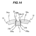
- Fig. 14 is a sectional view corresponding to Fig. 5, showing the positional relationship between the claws 5Aa 1 , 5Ba 1 of the claw-type magnetic poles 5A, 5B and the permanent magnet 7 provided in another modification of the above-described second embodiment of the vehicular alternator according to the present invention, in which a magnet holding portion is provided.
- Fig. 14 similar components to those in Fig. 5 are denoted by the same reference characters and a description thereof is omitted herein. In the following description, other drawings are also referred to, as an occasion requires.
- Fig. 14 shows only one pole constituted by each of the claws 5Aa 1 , 5Ba 1 as with Fig. 5.
- magnet holding portions 23Ba, 23Bb are provided respectively at an inner end (on the lower side in Fig. 14) and outer end (on the upper side in Fig. 14) of each of auxiliary magnetic pole plates 23B in the radial direction of the rotor 1 so as to grip the permanent magnet 7 between them. While the magnet holding portions 23Ba, 23Bb are provided in this modification, both the magnetic pole surfaces of the permanent magnet 7 are entirely held in contact with the auxiliary magnetic pole plates 23B. The remaining construction is the same as that of the second embodiment.
- the auxiliary magnetic pole plates 23A or 23B are previously bonded to the surfaces of the permanent magnet 7 (both the left and right lateral surfaces in Figs. 13 and 14), which are to be magnetized.
- the permanent magnet 7 including the auxiliary magnetic pole plates is disposed between the adjacent claws 5Aa 1 , 5Ba 1 of the claw-type magnetic poles 5A, 5B, and then magnetized through an external magnetizing yoke (not shown).
- the permanent magnet 7 is preferably magnetized in a final stage of the process for manufacturing the rotor 1.
- auxiliary magnetic pole plate 23B has substantially the same shape in a vertical section as viewed in Fig. 14.
- that shape of the auxiliary magnetic pole plate 23B eliminates the necessity of due care for checking which side is above when assembling the permanent magnet 7 including the auxiliary magnetic pole plates 23B, which have been bonded to the magnetized surfaces of the permanent magnet 7, between the adjacent claws 5Aa 1 , 5Ba 1 of the claw-type magnetic poles 5A, 5B.
- the permanent magnet 7 in a not yet magnetized state can be prevented from slipping off from the position between the claws of the claw-type magnetic poles 5A, 5B toward the side of the field windings 6, and the efficiency in works of, for example, assembling the rotor 1 and magnetizing the permanent magnet 7 can be improved.
- auxiliary magnetic pole portion 21' being effective to realize reinforcement of the strength and a smoother flow of the magnetic flux
- flange 22' being effective to reduce noise
- the present invention can also be applied to, e.g., a brushless vehicular alternator in which field windings are kept fixed.
- a brushless vehicular alternator in which field windings are kept fixed.
- the flanges 22, 22' are provided in the above embodiments as a structure for preventing the permanent magnet 7 from ejecting outward of the rotor 1 due to the rotation of the rotor 1, the present invention is not limited to such a structure.
- each claw is formed to have a greater width in the circumferential direction of the rotor on the outer side than on the inner side in the radial direction of the rotor, and a trapezoidal permanent magnet is formed to have a greater width in the circumferential direction of the rotor on the inner side than on the outer side in the radial direction of the rotor, the permanent magnet being disposed between adjacent claws.
- each claw of claw-type magnetic poles is formed to have a shape coming into contact with the whole of a magnetic pole surface of a permanent magnet, almost all of the magnetic flux outgoing from the permanent magnet is rendered to flow into the claw, whereby the resistance against a flow of the magnetic flux (i.e., magnetic loss) in the magnetic circuit formed by the permanent magnet can be reduced. It is therefore possible to effectively utilize the magnetic flux of the permanent magnet disposed between the adjacent claws of the claw-type magnetic poles, and to increase the output of the vehicular alternator.
- the second aspect of the present invention since an auxiliary magnetic pole plate contacting the whole of the magnetic pole surface of the permanent magnet is interposed between each claw and the permanent magnet, almost all of the magnetic flux outgoing from the permanent magnet is rendered to flow into the claw-type magnetic poles through the auxiliary magnetic pole plates, whereby the resistance against a flow of the magnetic flux (i.e., magnetic loss) in the magnetic circuit formed by the permanent magnet can be reduced. It is therefore possible to effectively utilize the magnetic flux of the permanent magnet disposed between the adjacent claws of the claw-type magnetic poles, and to increase the output of the vehicular alternator.
Landscapes
- Engineering & Computer Science (AREA)
- Power Engineering (AREA)
- Synchronous Machinery (AREA)
- Permanent Field Magnets Of Synchronous Machinery (AREA)
- Permanent Magnet Type Synchronous Machine (AREA)
Applications Claiming Priority (2)
| Application Number | Priority Date | Filing Date | Title |
|---|---|---|---|
| JP2001053017 | 2001-01-28 | ||
| JP2001053017A JP3740375B2 (ja) | 2001-02-27 | 2001-02-27 | 車両用交流発電機 |
Publications (3)
| Publication Number | Publication Date |
|---|---|
| EP1227566A2 true EP1227566A2 (de) | 2002-07-31 |
| EP1227566A3 EP1227566A3 (de) | 2004-06-16 |
| EP1227566B1 EP1227566B1 (de) | 2006-04-05 |
Family
ID=18913550
Family Applications (1)
| Application Number | Title | Priority Date | Filing Date |
|---|---|---|---|
| EP01119779A Expired - Lifetime EP1227566B1 (de) | 2001-02-27 | 2001-08-28 | Klauenpolgenerator mit Permanentmagneten |
Country Status (5)
| Country | Link |
|---|---|
| US (1) | US7057327B2 (de) |
| EP (1) | EP1227566B1 (de) |
| JP (1) | JP3740375B2 (de) |
| KR (1) | KR20020070068A (de) |
| DE (1) | DE60118515T2 (de) |
Cited By (7)
| Publication number | Priority date | Publication date | Assignee | Title |
|---|---|---|---|---|
| FR2865322A1 (fr) * | 2004-01-19 | 2005-07-22 | Mitsubishi Electric Corp | Machine dynamoelectrique a courant alternatif |
| EP1501169A3 (de) * | 2003-04-22 | 2006-08-30 | Delphi Technologies, Inc. | Elektrische Maschine in Hybridbauweise mit System und Verfahren zu ihrer Regelung |
| FR2901428A1 (fr) * | 2006-05-16 | 2007-11-23 | Valeo Equip Electr Moteur | Procede de realisation d'un rotor comportant une etape d'usinage de gorges dans les dents des poles et rotor obtenu par le procede |
| FR2932324A1 (fr) * | 2008-06-06 | 2009-12-11 | Valeo Equip Electr Moteur | Rotor de machine electrique tournante avec inserts magnetiques interpolaires |
| FR2932325A1 (fr) * | 2008-06-06 | 2009-12-11 | Valeo Equip Electr Moteur | Rotor de machine electrique tournante avec structures interpolaires a masse reduite |
| CN106655678A (zh) * | 2016-11-09 | 2017-05-10 | 陈元臣 | 新型高效双励磁无刷发电机 |
| EP2557661A3 (de) * | 2011-08-10 | 2017-11-22 | LG Innotek Co., Ltd. | Rotorkern für Motor |
Families Citing this family (45)
| Publication number | Priority date | Publication date | Assignee | Title |
|---|---|---|---|---|
| JP3882725B2 (ja) * | 2002-03-12 | 2007-02-21 | 株式会社デンソー | 車両用回転電機 |
| US6707227B1 (en) | 2002-12-11 | 2004-03-16 | Visteon Global Technologies, Inc. | High power alternator field coil |
| JP3821101B2 (ja) * | 2003-02-04 | 2006-09-13 | 株式会社日立製作所 | 直線駆動装置、その制御方法及びxyテーブル |
| JP4186759B2 (ja) * | 2003-09-03 | 2008-11-26 | 株式会社日立製作所 | 車両用交流発電機 |
| US7135784B2 (en) * | 2004-07-26 | 2006-11-14 | General Motors Corporation | Fast torque control of a belted alternator starter |
| JP4291235B2 (ja) | 2004-08-20 | 2009-07-08 | 株式会社日立製作所 | 車両用電源装置 |
| JP4396471B2 (ja) | 2004-10-01 | 2010-01-13 | 株式会社デンソー | 車両用回転電機およびその製造方法 |
| JP4410159B2 (ja) * | 2005-06-24 | 2010-02-03 | 三菱電機株式会社 | 交流回転電機 |
| JP4380652B2 (ja) * | 2005-08-26 | 2009-12-09 | 株式会社デンソー | 回転電機の回転子 |
| JP4524657B2 (ja) | 2005-09-01 | 2010-08-18 | 株式会社デンソー | 回転子の磁石保護構造及び磁石保護方法 |
| JP4692428B2 (ja) * | 2006-07-21 | 2011-06-01 | 株式会社デンソー | 車両用回転電機の回転子とその製造方法 |
| JP4735980B2 (ja) | 2006-08-23 | 2011-07-27 | 株式会社デンソー | 車両用交流発電機及びその製造方法 |
| US7989084B2 (en) | 2007-05-09 | 2011-08-02 | Motor Excellence, Llc | Powdered metal manufacturing method and devices |
| WO2008141214A1 (en) | 2007-05-09 | 2008-11-20 | Motor Excellence, Llc. | Electrical output generating devices and driven electrical devices with reduced flux leakage using permanent magnet components, and methods of making and using the same |
| JP4558008B2 (ja) * | 2007-06-19 | 2010-10-06 | 日立オートモティブシステムズ株式会社 | 回転電機 |
| FR2918220B1 (fr) * | 2007-06-27 | 2009-09-25 | Valeo Equip Electr Moteur | Ensemble interpolaire pour machine electrique tournante. |
| FR2929772B1 (fr) * | 2008-04-08 | 2016-01-15 | Leroy Somer Moteurs | Machine electrique comportant un ventilateur a canaux multiples |
| WO2010000996A2 (fr) * | 2008-06-06 | 2010-01-07 | Valeo Equipements Electriques Moteur | Rotor de machine electrique tournante avec structures interpolaires a masse reduite |
| JP2010016958A (ja) | 2008-07-02 | 2010-01-21 | Hitachi Ltd | 回転電機 |
| JP4858505B2 (ja) | 2008-07-29 | 2012-01-18 | 株式会社デンソー | 車両用回転電機 |
| DE102008043144B4 (de) * | 2008-10-24 | 2017-08-17 | Robert Bosch Gmbh | Vorrichtung zur Fixierung von Magneten |
| JP4743257B2 (ja) * | 2008-10-31 | 2011-08-10 | 株式会社デンソー | 回転電機の回転子およびその製造方法 |
| EP2182613B1 (de) | 2008-10-31 | 2018-02-28 | Denso Corporation | Rotor für eine rotierende elektrische Maschine |
| JP2012508549A (ja) | 2008-11-03 | 2012-04-05 | モーター エクセレンス, エルエルシー | 横方向および/またはコンミュテート式磁束システムの固定子の概念 |
| US20100301695A1 (en) | 2009-04-03 | 2010-12-02 | Asmo Co., Ltd. | Rotor and Motor |
| JP2010252554A (ja) * | 2009-04-16 | 2010-11-04 | Asmo Co Ltd | ロータ及びモータ |
| DE102009025929A1 (de) | 2009-06-05 | 2010-12-09 | Ulrich Spevacek | Läuferaufbau für eine permanentmagneterregte, rotierende elektrische Maschine |
| WO2011115633A1 (en) | 2010-03-15 | 2011-09-22 | Motor Excellence Llc | Transverse and/or commutated flux system for electric bicycles |
| WO2011115632A1 (en) | 2010-03-15 | 2011-09-22 | Motor Excellence Llc | Transverse and/or commutated flux systems configured to provide reduced flux leakage, hysteresis loss reduction, and phase matching |
| CN102959832B (zh) | 2010-03-15 | 2016-11-16 | 电扭矩机器股份有限公司 | 具有相偏移的横向和/或换向通量系统 |
| EP2385247B2 (de) | 2010-05-06 | 2025-06-18 | The Switch Engineering Oy | Elektromechanische Vorrichtung |
| ES2503736T3 (es) | 2010-05-06 | 2014-10-07 | Moventas Gears Oy | Un dispositivo electromecánico |
| ES2415505T3 (es) * | 2010-05-06 | 2013-07-25 | The Switch Drive Systems Oy | Una máquina eléctrica y un procedimiento para el montaje de ésta |
| DK2385611T3 (da) | 2010-05-06 | 2013-05-27 | Moventas Gears Oy | Elektromekanisk apparat |
| EP2641316B1 (de) | 2010-11-17 | 2019-02-13 | Motor Excellence, LLC | Quer- oder mischflusssysteme mit segmentierten statorlamellen |
| WO2012067896A2 (en) | 2010-11-17 | 2012-05-24 | Motor Excellence, Llc | Transverse and/or commutated flux systems having laminated and powdered metal portions |
| WO2012067895A2 (en) | 2010-11-17 | 2012-05-24 | Motor Excellence, Llc | Transverse and/or commutated flux system coil concepts |
| US9178396B2 (en) * | 2012-06-11 | 2015-11-03 | Tai-Her Yang | Cross-interlocked switch type DC electric machine having auxiliary excitation winding and conduction ring and brush |
| US9419547B2 (en) * | 2012-06-11 | 2016-08-16 | Tai-Her Yang | Switch type DC electric machine having auxiliary excitation winding and conduction ring and brush |
| US9000649B2 (en) * | 2012-06-11 | 2015-04-07 | Tai-Her Yang | Cross-interlocked multi-set switch type DC brushless electric machine system having auxiliary excitation winding set |
| US9035524B2 (en) * | 2012-06-11 | 2015-05-19 | Tai-Her Yang | Switch type DC brushless electric machine having auxiliary excitation winding set |
| US9214880B2 (en) * | 2012-06-11 | 2015-12-15 | Tai-Her Yang | Switch type DC electric machine having auxiliary excitation winding and conduction ring and brush |
| US9543797B2 (en) * | 2012-06-11 | 2017-01-10 | Tai-Her Yang | Cross-interlocked switch type DC electric machine having auxiliary excitation winding and conduction ring and brush |
| DE102012223711A1 (de) * | 2012-12-19 | 2014-06-26 | Robert Bosch Gmbh | Elektrische Maschine |
| JP6589931B2 (ja) * | 2016-06-03 | 2019-10-16 | 株式会社デンソー | 回転電機駆動システム |
Family Cites Families (31)
| Publication number | Priority date | Publication date | Assignee | Title |
|---|---|---|---|---|
| JPS6185045A (ja) * | 1984-03-08 | 1986-04-30 | Nippon Denso Co Ltd | 車両用交流発電機 |
| JP2946604B2 (ja) * | 1990-02-26 | 1999-09-06 | 株式会社デンソー | 交流発電機 |
| JP2890159B2 (ja) | 1993-04-13 | 1999-05-10 | ミネベア株式会社 | Oa機器用スピンドルモータ |
| JP3446313B2 (ja) * | 1993-08-30 | 2003-09-16 | 株式会社デンソー | 回転電機の回転子 |
| US5793144A (en) * | 1993-08-30 | 1998-08-11 | Nippondenso Co., Ltd. | Rotor for a rotating electric machine |
| JP3239630B2 (ja) | 1993-11-29 | 2001-12-17 | 株式会社デンソー | 車両用交流発電機 |
| US5780953A (en) * | 1993-12-07 | 1998-07-14 | Nippondenso Co., Ltd. | Alternator |
| JP3340259B2 (ja) * | 1994-03-23 | 2002-11-05 | 株式会社日立製作所 | 自動車用オルタネータ |
| JP2573163B2 (ja) | 1994-10-25 | 1997-01-22 | 下西技研工業株式会社 | マグネットキャッチ |
| JP3709582B2 (ja) * | 1995-08-11 | 2005-10-26 | 株式会社デンソー | 車両用交流発電機 |
| JP3709590B2 (ja) * | 1995-11-02 | 2005-10-26 | 株式会社デンソー | 車両用交流発電機 |
| JPH09163700A (ja) * | 1995-12-08 | 1997-06-20 | Mitsubishi Electric Corp | 交流発電機 |
| IL125761A (en) | 1996-02-15 | 2005-05-17 | Biosense Inc | Independently positionable transducers for location system |
| JPH09322451A (ja) | 1996-05-31 | 1997-12-12 | Toshiba Corp | モータ |
| DE19642784A1 (de) * | 1996-10-17 | 1998-04-23 | Bosch Gmbh Robert | Klauenpolgenerator |
| JP3530347B2 (ja) * | 1997-07-15 | 2004-05-24 | 新日本製鐵株式会社 | 動的変形特性に優れた高強度鋼板の選定方法 |
| JP3743113B2 (ja) * | 1997-05-07 | 2006-02-08 | 株式会社デンソー | 回転電機 |
| FR2764386B1 (fr) * | 1997-06-06 | 1999-07-16 | Commissariat Energie Atomique | Support d'electrodes comportant au moins une electrode recouverte par un depot et systeme de lecture de ce support |
| JPH11127561A (ja) * | 1997-10-22 | 1999-05-11 | Denso Corp | 磁石併用型回転電機の回転子及びその製造方法 |
| JP3767136B2 (ja) * | 1997-11-13 | 2006-04-19 | 三菱電機株式会社 | 回転電機の回転子及びその製造方法 |
| DE19802786A1 (de) * | 1998-01-26 | 1999-07-29 | Bosch Gmbh Robert | Synchronmaschine, insbesondere Generator oder Motor für ein Kraftfahrzeug |
| DE19806667A1 (de) * | 1998-02-18 | 1999-08-19 | Bosch Gmbh Robert | Synchronmaschine, insbesondere Generator für ein Kraftfahrzeug |
| JP3663958B2 (ja) * | 1998-03-05 | 2005-06-22 | 株式会社日立製作所 | 車両用交流発電機 |
| KR19990077581A (ko) * | 1998-03-05 | 1999-10-25 | 가나이 쓰도무 | 차량용교류발전기 |
| FR2784248B1 (fr) * | 1998-10-02 | 2000-12-22 | Valeo Equip Electr Moteur | Alternateur pour vehicule avec rattrapage de jeu sur les aimants interpolaires |
| JP3913933B2 (ja) * | 1999-05-24 | 2007-05-09 | 三菱電機株式会社 | 回転電機の回転子、その磁性体の着磁方法 |
| US6172441B1 (en) * | 1999-06-28 | 2001-01-09 | Visteon Global Technologies, Inc. | Rotor assembly |
| JP3155533B1 (ja) * | 1999-12-14 | 2001-04-09 | 三菱電機株式会社 | 車両用交流発電機 |
| JP3541934B2 (ja) * | 2000-01-11 | 2004-07-14 | 三菱電機株式会社 | 交流発電機の回転子 |
| JP3974315B2 (ja) * | 2000-07-25 | 2007-09-12 | 三菱電機株式会社 | 交流発電機 |
| JP3696062B2 (ja) * | 2000-08-10 | 2005-09-14 | 三菱電機株式会社 | 車両用交流発電機 |
-
2001
- 2001-02-27 JP JP2001053017A patent/JP3740375B2/ja not_active Expired - Fee Related
- 2001-08-28 EP EP01119779A patent/EP1227566B1/de not_active Expired - Lifetime
- 2001-08-28 DE DE60118515T patent/DE60118515T2/de not_active Expired - Fee Related
- 2001-08-30 US US09/941,655 patent/US7057327B2/en not_active Expired - Fee Related
- 2001-08-30 KR KR1020010052912A patent/KR20020070068A/ko not_active Ceased
Cited By (10)
| Publication number | Priority date | Publication date | Assignee | Title |
|---|---|---|---|---|
| EP1501169A3 (de) * | 2003-04-22 | 2006-08-30 | Delphi Technologies, Inc. | Elektrische Maschine in Hybridbauweise mit System und Verfahren zu ihrer Regelung |
| FR2865322A1 (fr) * | 2004-01-19 | 2005-07-22 | Mitsubishi Electric Corp | Machine dynamoelectrique a courant alternatif |
| US7847463B2 (en) | 2004-01-19 | 2010-12-07 | Mitsubishi Denki Kabushiki Kaisha | Alternating-current dynamoelectric machine |
| FR2901428A1 (fr) * | 2006-05-16 | 2007-11-23 | Valeo Equip Electr Moteur | Procede de realisation d'un rotor comportant une etape d'usinage de gorges dans les dents des poles et rotor obtenu par le procede |
| WO2007132105A3 (fr) * | 2006-05-16 | 2008-03-27 | Valeo Equip Electr Moteur | Procede de realisation d'un rotor comportant une etape d'usinage de gorges dans les dents des poles et rotor obtenu par le procede |
| US7969061B2 (en) | 2006-05-16 | 2011-06-28 | Valeo Equipments Electriques Moteur | Method for producing a rotor comprising a step of machining grooves in the teeth of the poles, and rotor obtained by said method |
| FR2932324A1 (fr) * | 2008-06-06 | 2009-12-11 | Valeo Equip Electr Moteur | Rotor de machine electrique tournante avec inserts magnetiques interpolaires |
| FR2932325A1 (fr) * | 2008-06-06 | 2009-12-11 | Valeo Equip Electr Moteur | Rotor de machine electrique tournante avec structures interpolaires a masse reduite |
| EP2557661A3 (de) * | 2011-08-10 | 2017-11-22 | LG Innotek Co., Ltd. | Rotorkern für Motor |
| CN106655678A (zh) * | 2016-11-09 | 2017-05-10 | 陈元臣 | 新型高效双励磁无刷发电机 |
Also Published As
| Publication number | Publication date |
|---|---|
| EP1227566B1 (de) | 2006-04-05 |
| US20020117934A1 (en) | 2002-08-29 |
| JP3740375B2 (ja) | 2006-02-01 |
| JP2002262530A (ja) | 2002-09-13 |
| KR20020070068A (ko) | 2002-09-05 |
| DE60118515T2 (de) | 2006-11-30 |
| EP1227566A3 (de) | 2004-06-16 |
| US7057327B2 (en) | 2006-06-06 |
| DE60118515D1 (de) | 2006-05-18 |
Similar Documents
| Publication | Publication Date | Title |
|---|---|---|
| EP1227566B1 (de) | Klauenpolgenerator mit Permanentmagneten | |
| EP2073361B1 (de) | Dynamoelektrische maschine | |
| US6333582B1 (en) | Rotor for an alternator | |
| US8749105B2 (en) | Magnetic inductor rotary machine and fluid transfer apparatus that uses the same | |
| EP2244362B1 (de) | Dynamoelektrische maschine | |
| JP3646446B2 (ja) | ランデルコア型回転電機 | |
| JP5047294B2 (ja) | 回転電機 | |
| JP3709590B2 (ja) | 車両用交流発電機 | |
| US8368274B2 (en) | Dynamoelectric machine and method for manufacturing a rotor therefor | |
| JP3819386B2 (ja) | 磁石発電機 | |
| US7211922B2 (en) | Rotor for rotating electric machine | |
| US8304951B2 (en) | Dynamoelectric machine | |
| US8546994B2 (en) | Dynamoelectric machine | |
| EP0156606B1 (de) | Generatorvorrichtung | |
| US8324780B2 (en) | Automotive dynamoelectric machine | |
| US20050116581A1 (en) | Rotor for dynamo-electric machine | |
| JP5157291B2 (ja) | 回転電機 | |
| JP2001086685A (ja) | 回転電機の回転子 | |
| JPH08317618A (ja) | 車両用交流発電機 | |
| JP2001178094A (ja) | 回転電機 |
Legal Events
| Date | Code | Title | Description |
|---|---|---|---|
| PUAI | Public reference made under article 153(3) epc to a published international application that has entered the european phase |
Free format text: ORIGINAL CODE: 0009012 |
|
| AK | Designated contracting states |
Kind code of ref document: A2 Designated state(s): AT BE CH CY DE DK ES FI FR GB GR IE IT LI LU MC NL PT SE TR |
|
| AX | Request for extension of the european patent |
Free format text: AL;LT;LV;MK;RO;SI |
|
| PUAL | Search report despatched |
Free format text: ORIGINAL CODE: 0009013 |
|
| AK | Designated contracting states |
Kind code of ref document: A3 Designated state(s): AT BE CH CY DE DK ES FI FR GB GR IE IT LI LU MC NL PT SE TR |
|
| AX | Request for extension of the european patent |
Extension state: AL LT LV MK RO SI |
|
| 17P | Request for examination filed |
Effective date: 20041007 |
|
| 17Q | First examination report despatched |
Effective date: 20050125 |
|
| AKX | Designation fees paid |
Designated state(s): DE FR GB IT |
|
| GRAP | Despatch of communication of intention to grant a patent |
Free format text: ORIGINAL CODE: EPIDOSNIGR1 |
|
| GRAS | Grant fee paid |
Free format text: ORIGINAL CODE: EPIDOSNIGR3 |
|
| GRAA | (expected) grant |
Free format text: ORIGINAL CODE: 0009210 |
|
| RIN1 | Information on inventor provided before grant (corrected) |
Inventor name: TAHARA, KAZUO,H Inventor name: KANAZAWA, HIROSHI,H Inventor name: SASAKI, SUSUMU,H Inventor name: TAKAHATA, RYOICHI,H Inventor name: MIYATA, KENJI,H Inventor name: KAWABATA, KAORU,H Inventor name: MAKI, KOHJI,H |
|
| RAP1 | Party data changed (applicant data changed or rights of an application transferred) |
Owner name: HITACHI, LTD. |
|
| AK | Designated contracting states |
Kind code of ref document: B1 Designated state(s): DE FR GB IT |
|
| REG | Reference to a national code |
Ref country code: GB Ref legal event code: FG4D |
|
| REF | Corresponds to: |
Ref document number: 60118515 Country of ref document: DE Date of ref document: 20060518 Kind code of ref document: P |
|
| PGFP | Annual fee paid to national office [announced via postgrant information from national office to epo] |
Ref country code: FR Payment date: 20060731 Year of fee payment: 6 |
|
| PGFP | Annual fee paid to national office [announced via postgrant information from national office to epo] |
Ref country code: GB Payment date: 20060818 Year of fee payment: 6 |
|
| PGFP | Annual fee paid to national office [announced via postgrant information from national office to epo] |
Ref country code: DE Payment date: 20060831 Year of fee payment: 6 Ref country code: IT Payment date: 20060831 Year of fee payment: 6 |
|
| ET | Fr: translation filed | ||
| PLBE | No opposition filed within time limit |
Free format text: ORIGINAL CODE: 0009261 |
|
| STAA | Information on the status of an ep patent application or granted ep patent |
Free format text: STATUS: NO OPPOSITION FILED WITHIN TIME LIMIT |
|
| 26N | No opposition filed |
Effective date: 20070108 |
|
| GBPC | Gb: european patent ceased through non-payment of renewal fee |
Effective date: 20070828 |
|
| REG | Reference to a national code |
Ref country code: FR Ref legal event code: ST Effective date: 20080430 |
|
| PG25 | Lapsed in a contracting state [announced via postgrant information from national office to epo] |
Ref country code: DE Free format text: LAPSE BECAUSE OF NON-PAYMENT OF DUE FEES Effective date: 20080301 |
|
| PG25 | Lapsed in a contracting state [announced via postgrant information from national office to epo] |
Ref country code: FR Free format text: LAPSE BECAUSE OF NON-PAYMENT OF DUE FEES Effective date: 20070831 |
|
| PG25 | Lapsed in a contracting state [announced via postgrant information from national office to epo] |
Ref country code: GB Free format text: LAPSE BECAUSE OF NON-PAYMENT OF DUE FEES Effective date: 20070828 |
|
| PG25 | Lapsed in a contracting state [announced via postgrant information from national office to epo] |
Ref country code: IT Free format text: LAPSE BECAUSE OF NON-PAYMENT OF DUE FEES Effective date: 20070828 |