EP1227678A2 - Technik zum Beseitigen von Bildartefakten mit einer effizienten Speicherverwaltung für Flüssigkristallprojektoren - Google Patents
Technik zum Beseitigen von Bildartefakten mit einer effizienten Speicherverwaltung für Flüssigkristallprojektoren Download PDFInfo
- Publication number
- EP1227678A2 EP1227678A2 EP02001352A EP02001352A EP1227678A2 EP 1227678 A2 EP1227678 A2 EP 1227678A2 EP 02001352 A EP02001352 A EP 02001352A EP 02001352 A EP02001352 A EP 02001352A EP 1227678 A2 EP1227678 A2 EP 1227678A2
- Authority
- EP
- European Patent Office
- Prior art keywords
- pixel
- image
- mask
- screen
- pixels
- Prior art date
- Legal status (The legal status is an assumption and is not a legal conclusion. Google has not performed a legal analysis and makes no representation as to the accuracy of the status listed.)
- Withdrawn
Links
Images


Classifications
-
- H—ELECTRICITY
- H04—ELECTRIC COMMUNICATION TECHNIQUE
- H04N—PICTORIAL COMMUNICATION, e.g. TELEVISION
- H04N5/00—Details of television systems
- H04N5/74—Projection arrangements for image reproduction, e.g. using eidophor
-
- G—PHYSICS
- G09—EDUCATION; CRYPTOGRAPHY; DISPLAY; ADVERTISING; SEALS
- G09G—ARRANGEMENTS OR CIRCUITS FOR CONTROL OF INDICATING DEVICES USING STATIC MEANS TO PRESENT VARIABLE INFORMATION
- G09G3/00—Control arrangements or circuits, of interest only in connection with visual indicators other than cathode-ray tubes
- G09G3/001—Control arrangements or circuits, of interest only in connection with visual indicators other than cathode-ray tubes using specific devices not provided for in groups G09G3/02 - G09G3/36, e.g. using an intermediate record carrier such as a film slide; Projection systems; Display of non-alphanumerical information, solely or in combination with alphanumerical information, e.g. digital display on projected diapositive as background
- G09G3/002—Control arrangements or circuits, of interest only in connection with visual indicators other than cathode-ray tubes using specific devices not provided for in groups G09G3/02 - G09G3/36, e.g. using an intermediate record carrier such as a film slide; Projection systems; Display of non-alphanumerical information, solely or in combination with alphanumerical information, e.g. digital display on projected diapositive as background to project the image of a two-dimensional display, such as an array of light emitting or modulating elements or a CRT
-
- G—PHYSICS
- G06—COMPUTING OR CALCULATING; COUNTING
- G06T—IMAGE DATA PROCESSING OR GENERATION, IN GENERAL
- G06T5/00—Image enhancement or restoration
- G06T5/20—Image enhancement or restoration using local operators
-
- G—PHYSICS
- G06—COMPUTING OR CALCULATING; COUNTING
- G06T—IMAGE DATA PROCESSING OR GENERATION, IN GENERAL
- G06T5/00—Image enhancement or restoration
- G06T5/73—Deblurring; Sharpening
- G06T5/75—Unsharp masking
-
- G—PHYSICS
- G09—EDUCATION; CRYPTOGRAPHY; DISPLAY; ADVERTISING; SEALS
- G09G—ARRANGEMENTS OR CIRCUITS FOR CONTROL OF INDICATING DEVICES USING STATIC MEANS TO PRESENT VARIABLE INFORMATION
- G09G5/00—Control arrangements or circuits for visual indicators common to cathode-ray tube indicators and other visual indicators
- G09G5/10—Intensity circuits
-
- H—ELECTRICITY
- H04—ELECTRIC COMMUNICATION TECHNIQUE
- H04N—PICTORIAL COMMUNICATION, e.g. TELEVISION
- H04N5/00—Details of television systems
- H04N5/14—Picture signal circuitry for video frequency region
- H04N5/21—Circuitry for suppressing or minimising disturbance, e.g. moiré or halo
-
- H—ELECTRICITY
- H04—ELECTRIC COMMUNICATION TECHNIQUE
- H04N—PICTORIAL COMMUNICATION, e.g. TELEVISION
- H04N5/00—Details of television systems
- H04N5/74—Projection arrangements for image reproduction, e.g. using eidophor
- H04N5/7416—Projection arrangements for image reproduction, e.g. using eidophor involving the use of a spatial light modulator, e.g. a light valve, controlled by a video signal
- H04N5/7441—Projection arrangements for image reproduction, e.g. using eidophor involving the use of a spatial light modulator, e.g. a light valve, controlled by a video signal the modulator being an array of liquid crystal cells
-
- H—ELECTRICITY
- H04—ELECTRIC COMMUNICATION TECHNIQUE
- H04N—PICTORIAL COMMUNICATION, e.g. TELEVISION
- H04N9/00—Details of colour television systems
- H04N9/12—Picture reproducers
- H04N9/31—Projection devices for colour picture display, e.g. using electronic spatial light modulators [ESLM]
- H04N9/3179—Video signal processing therefor
-
- G—PHYSICS
- G06—COMPUTING OR CALCULATING; COUNTING
- G06T—IMAGE DATA PROCESSING OR GENERATION, IN GENERAL
- G06T2207/00—Indexing scheme for image analysis or image enhancement
- G06T2207/20—Special algorithmic details
- G06T2207/20004—Adaptive image processing
- G06T2207/20012—Locally adaptive
-
- G—PHYSICS
- G09—EDUCATION; CRYPTOGRAPHY; DISPLAY; ADVERTISING; SEALS
- G09G—ARRANGEMENTS OR CIRCUITS FOR CONTROL OF INDICATING DEVICES USING STATIC MEANS TO PRESENT VARIABLE INFORMATION
- G09G2320/00—Control of display operating conditions
- G09G2320/02—Improving the quality of display appearance
-
- H—ELECTRICITY
- H04—ELECTRIC COMMUNICATION TECHNIQUE
- H04N—PICTORIAL COMMUNICATION, e.g. TELEVISION
- H04N5/00—Details of television systems
- H04N5/74—Projection arrangements for image reproduction, e.g. using eidophor
- H04N5/7416—Projection arrangements for image reproduction, e.g. using eidophor involving the use of a spatial light modulator, e.g. a light valve, controlled by a video signal
- H04N5/7441—Projection arrangements for image reproduction, e.g. using eidophor involving the use of a spatial light modulator, e.g. a light valve, controlled by a video signal the modulator being an array of liquid crystal cells
- H04N2005/745—Control circuits therefor
Definitions
- This invention relates to a memory efficient method and apparatus for removing image artifacts including moiré from screen images, particularly images generated by liquid crystal projectors (LCPs).
- the invention also relates to a program of instructions for implementing various aspects of the image artifact removal technique.
- Moiré artifacts may result whenever two geometrically-regular patterns are superimposed and often manifests itself as a ripple-like pattern in the image representations. Such artifacts degrade image quality and are therefore undesirable.
- the image-generating projection device may employ a technique known as a "keystone correction" which alters the shape of the projected image to compensate for the angle of projection. While the keystone correction improves certain characteristics of the projected image, it has a disadvantage in that it is usually not able to maintain equal spacing between screen line/dot patterns. Consequently, the unequal spacing at different locations in the image results in moiré artifacts.
- LPF low pass filter
- a memory efficient method for removing image artifacts from an image representation comprises the steps of (a) obtaining a pixel representation of the image; (b) classifying each pixel in the image as a screen or non-screen pixel; (c) examining pixels in a predetermined surrounding area of each pixel to check the classification of that pixel as determined in step (b); and (d) selectively applying a low pass filter to pixels in the image, such that, when the low pass filter is applied, one or more pixels covered by the low pass filter are respectively replaced by one or more other pixels covered by the low pass filter based on the examining in step (c).
- the classifying step (b) comprises applying a first mask of a predetermined size centered on the pixel being classified to determine if the center pixel is in an area having a predetermined periodic pattern.
- the first mask is divided into a plurality of overlapping areas, the center pixel being in each of the first mask areas.
- the examining step (c) comprises applying a second mask of a predetermined size centered on the pixel being checked.
- the second mask is divided into a plurality of overlapping areas, the center pixel being in each of the second mask areas.
- the predetermined periodic pattern is a periodic line or dot pattern having a period of 2 or 3.
- the selectively applying step (e) comprises selectively applying the low pass filter based on which of the plurality of second mask areas contains screen pixels.
- the above-described method may further comprise the steps of (f) determining a feature indicator for at least one portion of the image; and (g) adaptively sharpening or softening the at least one portion of the image based on the determined feature indicator.
- Such apparatus comprises a device for obtaining a pixel representation of the image; a screen pixel identifier, in communication with the device, for classifying each pixel in the image as a screen or non-screen pixel; a screen region verifier, in communication with the screen pixel identifier, for examining pixels in a predetermined surrounding area of each pixel to check the classification of that pixel as determined by screen pixel identifier; and a low pass filter, in communication with the screen region verifier, that is selectively applied to the pixels in the image, such that, when the low pass filter is applied, one or more pixels covered by the low pass filter are respectively replaced by one or more other pixels covered by the low pass filter based on the examining.
- the screen pixel identifier comprises a first mask of a predetermined size that is applied by centering the first mask on the pixel being classified to determine if the center pixel is in an area having a predetermined periodic pattern.
- the first mask is divided into a plurality of overlapping areas, the center pixel being in each of the first mask areas.
- the screen region verifier comprises a second mask of a predetermined size that is applied by centering the second mask on the pixel being checked.
- the second mask is divided into a plurality of overlapping areas, the center pixel being in each of the second mask areas.
- the predetermined periodic pattern is a periodic line or dot pattern having a period of 2 or 3.
- the low pass filter is selectively applied based on which of the plurality of second mask areas contains screen pixels.
- the apparatus described above may further comprise a frequency classifier that determines a feature indicator for at least one portion of the image; and an image processor for adaptively sharpening or softening the at least one portion of the image based on the determined feature indicator.
- the above-described method or steps thereof may be embodied in a program of instructions (e.g., software) which may be stored on, or conveyed to, a computer or other processor-controlled device for execution.
- a program of instructions e.g., software
- the method or steps thereof may be implemented using hardware or a combination of software and hardware.
- Fig. 1 illustrates components in a typical image projection system 10 in which the techniques of the present invention can be employed.
- a computer system 12 stores digital images that are electrically transmitted along a suitable transmission path 14 to a projecting device 16, such as a liquid crystal projector (LCP) which projects such images onto a screen, wall or other display area.
- a projecting device 16 such as a liquid crystal projector (LCP) which projects such images onto a screen, wall or other display area.
- LCP liquid crystal projector
- Fig. 1 represents just one of many alternatives available for obtaining digital images and projecting them.
- the present invention concerns certain processing applied to the digital images before they are displayed or projected, and for the purpose of this invention, it is not important how or where the images are stored or digitized.
- Digital images to be processed in accordance with the invention may, be obtained from scanners, digital cameras, etc., stored in a memory, and transmitted to the projecting device. Such digital images may also be computer generated. Moreover, the special processing which is the subject of the present invention may occur either in the projecting device itself, or in a computer or other device capable of performing the processing of the invention prior to transmission of the processed image data to the projecting device.
- computer 12 In the case where digitized images are obtained, stored and processed by computer 12, such computer may be of any suitable type, including a personal computer or workstation. As illustrated in Fig. 2, the computer typically includes a central processing unit (CPU) 21 that provides computing resources and controls the computer. CPU 21 may be implemented with a microprocessor or the like, and may also include a graphics processor and/or a floating point coprocessor for mathematical computations. Computer 12 further includes system memory 22 which may be in the form of random-access memory (RAM) and read-only memory (ROM).
- RAM random-access memory
- ROM read-only memory
- Input controllers 23 represents an interface to one or more input devices 24, such as a keyboard, mouse or stylus.
- Computer system 12 may also have input controllers for connecting an input device such as a scanner and/or digital camera from which digital images may be obtained.
- a storage controller 25 is an interface to a storage device 26 that includes a storage medium such as magnetic tape or disk, or an optical medium that may be used to record programs of instructions for operating systems, utilities and applications which may include embodiments of programs that implement various aspects of the present invention.
- Storage device 26 may also be used to store image data to be processed in accordance with the invention.
- Output controllers 27 provide interfaces to output devices 28 such as a display device which may be a cathode ray tube (CRT) or thin film transistor (TFT) display. An output controller is also provided for connecting projecting device 16 to computer 12. Communications controller 29 interfaces with communication device 31 which may be a modem or other network connection. Programs that implement various aspects of this invention and/or processed or to be processed image data may be transmitted to computer 12 from a remote location (e.g., a server) over a network.
- a remote location e.g., a server
- bus 32 which may represent more than one physical bus.
- ISA Industry Standard Architecture
- Other computers incorporate an ISA bus as well as a higher bandwidth bus.
- Fig. 3 illustrates a processor 100, which may be embodied in computer 12, in the projecting device 16, or other suitable device, for performing various functions, including keystone image artifact removal (KIAR) 35, adaptive field-based video enhancement (AFBVE) 36, which KIAR is designed to support, and keystone morphing 37.
- KIAR keystone image artifact removal
- AFBVE adaptive field-based video enhancement
- keystone morphing The relationship between KIAR, AFBVE and keystone morphing is illustrated in the figure.
- the input image (I/P) is transmitted to the KIAR block where it is processed in accordance with the KIAR technique.
- the KIAR processed image is then transmitted to the AFBVE block where it may be further processed in accordance with the AFBVE technique.
- Keystone morphing may then be applied to AFBVE processed image to generate an output image (O/P) that is displayed by LCP 16.
- the KIAR, AFBVE and keystone morphing operations may be implemented in processor 100 in a variety of ways including by software, hardware, or combination thereof.
- Such software may be stored on computer 12 in system memory 22 or in storage device 26, and fetched by CPU 21 for execution. More broadly, such software may be conveyed by any of a variety of machine-readable medium including magnetic tape or disk, optical disc, signals transmitted through network paths including the Internet, as well as other suitable carrier signals throughout the electromagnetic spectrum including infrared signals.
- Processor 100 may also be implemented with discrete logic circuits, one or more application specific integrated circuits (ASICs), digital signal processors, program-controlled processors, or the like.
- ASICs application specific integrated circuits
- Fig. 4 is a functional block diagram of the KIAR technique in accordance with embodiments of the invention.
- KIAR 35 is implemented with a screen pixel identifier (SPI) 41, a screen region verifier (SRV) 42 and a filter 43 such as a low pass filter (LPF).
- SPI 41 examines each pixel of a digital image input to KIAR block 35 and classifies that pixel as either a screen or non-screen pixel.
- SRV 42 examines surrounding area pixels to check if the initial classification was correct and to reclassify any pixels misclassified by SPI 41.
- a LPF is then applied to screen region pixels, as described below, while keeping the non-screen region pixels unchanged.
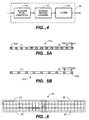
- SPI 41 employs a one-dimensional mask, one embodiment of which is schematically illustrated in Fig. 5A and another of which is shown in Fig. 5B, to perform its classification function.
- Masks 51a and 51b each have a size of 25 x 1 pixels and is centered on the pixel currently being examined.
- the mask elements 52a and 52b are spaced so as to check if the center pixel is in a periodic line or dot pattern area, where the period or distance (dist) between pixels corresponding to adjacent mask elements is equal to some predetermined number.
- elements 52a are spaced so that the predetermined number is 2. That is, there is one pixel between each pixel that corresponds to a mask element and that is examined.
- elements 52b are spaced so that the predetermined number is 3. That is, there are two pixels between each pixel that corresponds to a mask element and that is examined.
- each mask 51a and 51b is divided into overlapping areas (1) and (2) with one pixel overlap in the center. Such division is done to facilitate the identification of screen pixels on borders and in corners.
- Each area (1) and (2) corresponds to 5 or 7 pixel locations, with spacing denoted by "dist" as 2 or 3 pixels.
- Mask 51a examines 7 pixels in each area with a spacing of 2 pixels
- mask 51b examines 5 pixels in each area with a spacing of 3 pixels.
- any pixel misclassifications are corrected by SRV 42 which also employs a mask.
- the SPI mask is 25 x 1
- the SRV mask 61 is preferably 25 x 3 pixels and is divided into quadrants denoted [1], [2], [3] and [4], as illustrated in Fig. 6.
- Each quadrant is preferably 13 x 2 pixels with one horizontal and vertical line overlap between adjacent quadrants. That is, the right-most column in quadrant [1] overlaps with the left-most column in quadrant [2], and the lower-most row of quadrant [1] overlaps with the upper-most row of quadrant [3].
- a filter kernel of LPF 43 is applied based on the processing with the SRV mask.
- the filter kernel is preferably a 3 x 3 Gaussian LPF kernel whose coefficients are shown in Fig. 7.
- the manner in which the LPF kernel is applied depends on which combination of quadrants of the SRV mask 61 contain screen pixels. If all of the pixels in each of the four quadrants of SRV mask 61 are screen pixels, then the LPF kernel is applied to smooth the center pixel, which is the darkened pixel in Fig. 6. However, if only some quadrants contain screen pixels, the corresponding pixels are replaced by "mirror" pixels, as described below with reference to Fig. 8 which denotes the numbering of the pixels covered by the LPF kernel.
- pixel 9 is replaced by pixel 1. If only quadrants [1], [2] and [4] contain screen pixels, pixel 7 is replaced by pixel 3. If only quadrants [1], [3] and [4] contain screen pixels, pixel 3 is replaced by pixel 7. If only quadrants [2], [3], and [4] contain screen pixels, pixel 1 is replaced by pixel 9. If only quadrants [1] and [2] contain screen pixels, pixels 7, 8, and 9 are replaced by pixels 1, 2, and 3, respectively. If only quadrants [1] and [3] contain screen pixels, pixels 3, 6, and 9 are replaced by pixels 1, 4, and 7, respectively.
- pixels 1, 4, and 7 are replaced by pixels 3, 6, and 9, respectively. If only quadrants [3] and [4] contain screen pixels, pixels 1, 2, and 3 are replaced by pixels 7, 8, and 9, respectively. If only quadrant [1] contains screen pixels, pixels 3, 6, 9, 8, and 7 are replaced by pixels 1, 2, 1, 4, and 1, respectively. If only quadrant [2] contains screen pixels, pixels 1, 4, 7, 8, and 9 are replaced by pixels 3, 2, 3, 6, and 3, respectively. If only quadrant [3] contains screen pixels, pixels 1, 2, 3, 6, and 9 are replaced by pixels 7, 4, 7, 8, and 7, respectively. If only quadrant [4] contains screen pixels, pixels 3, 2, 1, 4, and 7 are replaced by pixels 9, 6, 9, 8, and 9, respectively. In all other cases, the pixel being examined is left unchanged. That is, the LPF is not applied.
- the KIAR technique may be employed with another technique known as Adaptive Field-Based Video Enhancement (AFBVE).
- AFBVE is an adaptive process that is used to smooth or sharpen edges or boundaries, as needed, to remove blurring caused by interlaced video input, which is the separate input to the LCP of odd and even image pixel lines.
- interlaced video input usually the odd pixel lines are input first, followed by the even pixel lines. Either way, such an input results in each video frame being comprised of two fields: an odd line field and an even line field. These interaction between these two fields tends to cause blurring in the resulting image.
- AFBVE is designed to correct this type of blurring.
- Fig. 9 is a functional block diagram of the AFBVE technique which adaptively applies sharpening and smoothing to the digital output of the KIAR block 35.
- the output of KIAR 35 forms the input image, which is interlaced or progressive data, to AFBVE 36.
- This input image is transmitted to LPF 91, a first summing function 92, and a frequency classifier 93.
- LPF 91 low-pass filters the input image to obtain a smooth (i.e., softened image).
- LPF 91 preferably uses the same 3 x 3 Gaussian kernel illustrated in Fig. 7.
- the smoothened image is subtracted from the input image to obtain the high pass frequency components of the image which forms the other input to first summing function 92.
- Element 92 combines the input image and the high pass frequency components and transmits the result to a scale factor determiner 94 which generates a scaling factor for magnifying the high frequency components of the image.
- a scaling factor of 1 means that the output image of the AFBVE function is to be the same as the function's input image; a scaling factor greater than 1 means the output image is to be sharpened; and a scaling factor of less than 1 means the output image is to be softened.
- the frequency classifier 93 of the present invention produces a feature indicator, denoted by " f " in Fig. 9, to modulate the scaling factor to achieve adaptive sharpening and softening enhancement.
- Frequency classifier 93 determines which image areas are to be sharpened and which are to be softened and also determines the magnitude of the sharpening or softening factor to be applied at each pixel location in the image. That is, frequency classifier 93 detects image spatial frequency information in order to separate primary edges from noisy micro-edges (or non-edges) to produce the feature indicator, f .
- frequency classifier 93 uses 3 x 3 Sobel edge detectors to detect spatial frequency components of the image and classify each component into one of the three regions illustrated in Fig. 10.
- the three regions are: a softening region which is below a predetermined lower threshold frequency (thr_low), a sharpening region above a predetermined upper threshold (thr_high), and a transition region between the softening and sharpening regions.
- the transition region provides a smooth transition between softening and sharpening enhancement.
- f is linear in the transition region to avoid discontinuity artifacts between the softening and sharpening regions.
- feature indicator, f is a function of the output of the Sobel edge detectors, which has a range of 0 - 255.
- the thr_low and thr_high will vary depending on the type of image, personal visual preferences and system hardware characteristics. Such thresholds can be experimentally determined. However, the inventors have determined that for many images a thr_low of about 20 and thr_high of about 40 yields good results.
- the feature indicator f which is number from 0 to 1 (expressed as a percentage between 0 and 100% in Fig. 10), is input to a multiplier 95 where it is multiplied with the scaling factor of scale factor determiner 94 to produce a modulated scaling factor which is applied by summer 96 to the smoothed image produced by LPF 91.
- a modulated scaling factor of 1 means that no change is applied to output of LPF 91; a scaling factor greater than 1 means that such output is sharpened; and a scaling factor of less than 1 means that such output is softened or smoothed.
- the resulting image from summer 96 is the output (O/P) image of the AFBVE process.
- Fig. 11A is a graphical representation of an interlaced video image which may be input to an LCP.
- each frame contains two fields: a first field which contains, say, all of the odd scan lines and a second field which contains, say, all of the even scan lines.
- Each image data field is processed separately, for example, the first field is processed followed by the second field.
- a filter kernel is applied to elements from either the first or the second fields, as schematically illustrated in Fig. 11B.
- the interlaced video format is only one type of video input for an LCP.
- a progressive format an image of which has a line-by-line raster format, may also be used.
- the present invention provides a technique (KIAR) for smoothing non-screen image regions to remove moiré therefrom while maintaining sharpness in the non-screen regions.
- the KIAR process may be followed by an AFBVE process, each of which may be conveniently implemented in a personal computer or other processing device using software, hardware, or combination thereof.
Landscapes
- Engineering & Computer Science (AREA)
- Physics & Mathematics (AREA)
- General Physics & Mathematics (AREA)
- Theoretical Computer Science (AREA)
- Signal Processing (AREA)
- Multimedia (AREA)
- Computer Hardware Design (AREA)
- Chemical & Material Sciences (AREA)
- Crystallography & Structural Chemistry (AREA)
- Image Processing (AREA)
- Facsimile Image Signal Circuits (AREA)
- Image Analysis (AREA)
- Apparatus For Radiation Diagnosis (AREA)
Applications Claiming Priority (2)
| Application Number | Priority Date | Filing Date | Title |
|---|---|---|---|
| US766123 | 1985-08-15 | ||
| US09/766,123 US6879734B2 (en) | 2001-01-18 | 2001-01-18 | Memory efficient image artifact removal technique for LCP |
Publications (2)
| Publication Number | Publication Date |
|---|---|
| EP1227678A2 true EP1227678A2 (de) | 2002-07-31 |
| EP1227678A3 EP1227678A3 (de) | 2003-08-27 |
Family
ID=25075472
Family Applications (1)
| Application Number | Title | Priority Date | Filing Date |
|---|---|---|---|
| EP02001352A Withdrawn EP1227678A3 (de) | 2001-01-18 | 2002-01-18 | Technik zum Beseitigen von Bildartefakten mit einer effizienten Speicherverwaltung für Flüssigkristallprojektoren |
Country Status (5)
| Country | Link |
|---|---|
| US (1) | US6879734B2 (de) |
| EP (1) | EP1227678A3 (de) |
| JP (1) | JP4123780B2 (de) |
| KR (1) | KR100521962B1 (de) |
| CN (1) | CN1258745C (de) |
Families Citing this family (9)
| Publication number | Priority date | Publication date | Assignee | Title |
|---|---|---|---|---|
| US7599576B2 (en) * | 2004-01-23 | 2009-10-06 | Electro Scientific Industries, Inc. | Image subtraction of illumination artifacts |
| US7483059B2 (en) * | 2004-04-30 | 2009-01-27 | Hewlett-Packard Development Company, L.P. | Systems and methods for sampling an image sensor |
| US7783117B2 (en) * | 2005-08-12 | 2010-08-24 | Seiko Epson Corporation | Systems and methods for generating background and foreground images for document compression |
| US7899258B2 (en) * | 2005-08-12 | 2011-03-01 | Seiko Epson Corporation | Systems and methods to convert images into high-quality compressed documents |
| WO2007029235A2 (en) * | 2005-09-05 | 2007-03-15 | Algosoft Limited | Automatic digital film and video restoration |
| JP4215038B2 (ja) * | 2005-09-16 | 2009-01-28 | セイコーエプソン株式会社 | 画像処理装置、画像処理方法、およびプログラム |
| US7894689B2 (en) * | 2007-05-31 | 2011-02-22 | Seiko Epson Corporation | Image stitching |
| JP5736652B2 (ja) * | 2010-03-09 | 2015-06-17 | セイコーエプソン株式会社 | 画像表示装置および画像表示方法 |
| US11109005B2 (en) * | 2019-04-18 | 2021-08-31 | Christie Digital Systems Usa, Inc. | Device, system and method for enhancing one or more of high contrast regions and text regions in projected images |
Family Cites Families (9)
| Publication number | Priority date | Publication date | Assignee | Title |
|---|---|---|---|---|
| US4194221A (en) * | 1978-12-26 | 1980-03-18 | Xerox Corporation | Automatic multimode continuous halftone line copy reproduction |
| GB2170373B (en) | 1984-12-28 | 1989-03-15 | Canon Kk | Image processing apparatus |
| JPH0683374B2 (ja) * | 1986-02-14 | 1994-10-19 | 富士写真フイルム株式会社 | 網点画像の形成方法 |
| JPS6460087A (en) | 1987-08-31 | 1989-03-07 | Canon Kk | Signal processing circuit |
| JP3050282B2 (ja) | 1996-03-06 | 2000-06-12 | 日本電気株式会社 | 液晶プロジェクタの歪み補正装置 |
| US5798846A (en) * | 1996-05-28 | 1998-08-25 | Hewlett-Packard Company | Apparatus and method for selectively processing a scanned image |
| US6160913A (en) * | 1998-03-25 | 2000-12-12 | Eastman Kodak Company | Method and apparatus for digital halftone dots detection and removal in business documents |
| US6633411B1 (en) * | 1998-04-01 | 2003-10-14 | International Business Machines Corporation | Method and apparatus for repurposing binary images |
| EP1079601B1 (de) | 1999-03-05 | 2008-06-18 | Seiko Epson Corporation | Korrigiervorrichtung für bilddaten, korrigierverfahren für bilddaten, träger auf welchem ein bilddatenkorrigierprogramm aufgezeichnet ist. |
-
2001
- 2001-01-18 US US09/766,123 patent/US6879734B2/en not_active Expired - Fee Related
- 2001-12-29 KR KR10-2001-0087969A patent/KR100521962B1/ko not_active Expired - Fee Related
-
2002
- 2002-01-18 JP JP2002010696A patent/JP4123780B2/ja not_active Expired - Fee Related
- 2002-01-18 EP EP02001352A patent/EP1227678A3/de not_active Withdrawn
- 2002-01-18 CN CNB021018006A patent/CN1258745C/zh not_active Expired - Fee Related
Also Published As
| Publication number | Publication date |
|---|---|
| EP1227678A3 (de) | 2003-08-27 |
| KR100521962B1 (ko) | 2005-10-17 |
| US20020094129A1 (en) | 2002-07-18 |
| KR20020061494A (ko) | 2002-07-24 |
| JP4123780B2 (ja) | 2008-07-23 |
| US6879734B2 (en) | 2005-04-12 |
| CN1366275A (zh) | 2002-08-28 |
| JP2002259963A (ja) | 2002-09-13 |
| CN1258745C (zh) | 2006-06-07 |
Similar Documents
| Publication | Publication Date | Title |
|---|---|---|
| US6879733B2 (en) | Image artifact removal technique for LCP | |
| US20030053692A1 (en) | Method of and apparatus for segmenting a pixellated image | |
| US7796139B1 (en) | Methods and apparatus for displaying a frame with contrasting text | |
| US7783130B2 (en) | Spatial standard observer | |
| US20250095158A1 (en) | Methods and Systems for Automatically Generating Backdrop Imagery for a Graphical User Interface | |
| JPH1115947A (ja) | 画像処理装置 | |
| US6600518B1 (en) | Adaptive clipping prevention for picture sharpness enhancement | |
| JP5781370B2 (ja) | 画像処理装置、画像処理方法、画像処理装置を備える画像表示装置、プログラムおよび記録媒体 | |
| US6879734B2 (en) | Memory efficient image artifact removal technique for LCP | |
| KR100560027B1 (ko) | 압축 에지 적응형 비디오 및 화상의 샤프닝 및 스캐일링 | |
| US20150248221A1 (en) | Image processing device, image processing method, image processing system, and non-transitory computer readable medium | |
| US6862366B2 (en) | Techniques for scratch and date removal from scanned film | |
| JPWO2014102876A1 (ja) | 画像処理装置、および、画像処理方法 | |
| JP4366634B2 (ja) | ノイズ画素マップ作成方法とその方法を実施する装置とプログラム及び写真プリント装置 | |
| JP2001160142A (ja) | 画像の鮮鋭度判断方法、画像の鮮鋭度を判断する処理を行うためのプログラムを記録した記録媒体、画像処理装置および写真焼付装置 | |
| JP2000022939A (ja) | 画像縮小装置及び画像縮小プログラムを記録した記録媒体 | |
| CN111340736B (zh) | 图像处理方法、装置、存储介质及电子设备 | |
| JPH0348980A (ja) | 輪郭強調処理方式 | |
| CN112449073A (zh) | 图像检查装置、图像形成装置以及图像检查方法 | |
| JP3912063B2 (ja) | 画像濃淡ムラの検出方法 | |
| JP4930638B2 (ja) | 画像補正装置および画像補正方法 | |
| CN107231551A (zh) | 一种图像检测方法及装置 |
Legal Events
| Date | Code | Title | Description |
|---|---|---|---|
| PUAI | Public reference made under article 153(3) epc to a published international application that has entered the european phase |
Free format text: ORIGINAL CODE: 0009012 |
|
| AK | Designated contracting states |
Kind code of ref document: A2 Designated state(s): AT BE CH CY DE DK ES FI FR GB GR IE IT LI LU MC NL PT SE TR |
|
| AX | Request for extension of the european patent |
Free format text: AL;LT;LV;MK;RO;SI |
|
| PUAL | Search report despatched |
Free format text: ORIGINAL CODE: 0009013 |
|
| AK | Designated contracting states |
Designated state(s): AT BE CH CY DE DK ES FI FR GB GR IE IT LI LU MC NL PT SE TR |
|
| AX | Request for extension of the european patent |
Extension state: AL LT LV MK RO SI |
|
| 17P | Request for examination filed |
Effective date: 20040204 |
|
| AKX | Designation fees paid |
Designated state(s): DE FR GB |
|
| 17Q | First examination report despatched |
Effective date: 20080226 |
|
| STAA | Information on the status of an ep patent application or granted ep patent |
Free format text: STATUS: THE APPLICATION IS DEEMED TO BE WITHDRAWN |
|
| 18D | Application deemed to be withdrawn |
Effective date: 20110802 |