EP1228501B1 - System und verfahren zur ultraschall-laseruntersuchung mit einem laser abstimmbarer wellenlänge zur ultraschallerzeugung - Google Patents
System und verfahren zur ultraschall-laseruntersuchung mit einem laser abstimmbarer wellenlänge zur ultraschallerzeugung Download PDFInfo
- Publication number
- EP1228501B1 EP1228501B1 EP00968312A EP00968312A EP1228501B1 EP 1228501 B1 EP1228501 B1 EP 1228501B1 EP 00968312 A EP00968312 A EP 00968312A EP 00968312 A EP00968312 A EP 00968312A EP 1228501 B1 EP1228501 B1 EP 1228501B1
- Authority
- EP
- European Patent Office
- Prior art keywords
- laser
- wavelength
- laser beam
- ultrasonic
- remote target
- Prior art date
- Legal status (The legal status is an assumption and is not a legal conclusion. Google has not performed a legal analysis and makes no representation as to the accuracy of the status listed.)
- Expired - Lifetime
Links
- 238000000034 method Methods 0.000 title claims abstract description 46
- 238000012360 testing method Methods 0.000 title description 12
- 238000002604 ultrasonography Methods 0.000 title description 11
- 238000006073 displacement reaction Methods 0.000 claims abstract description 56
- 230000003287 optical effect Effects 0.000 claims description 24
- 230000007246 mechanism Effects 0.000 claims description 4
- RTAQQCXQSZGOHL-UHFFFAOYSA-N Titanium Chemical compound [Ti] RTAQQCXQSZGOHL-UHFFFAOYSA-N 0.000 claims description 3
- 229910052719 titanium Inorganic materials 0.000 claims description 3
- 239000010936 titanium Substances 0.000 claims description 3
- 230000004044 response Effects 0.000 claims description 2
- 238000001914 filtration Methods 0.000 claims 1
- 238000001514 detection method Methods 0.000 abstract description 8
- 230000008569 process Effects 0.000 abstract description 3
- 238000012545 processing Methods 0.000 abstract description 2
- 239000000463 material Substances 0.000 description 20
- 230000002123 temporal effect Effects 0.000 description 14
- 238000007689 inspection Methods 0.000 description 13
- 239000002131 composite material Substances 0.000 description 12
- 238000011156 evaluation Methods 0.000 description 6
- 230000001066 destructive effect Effects 0.000 description 5
- 239000013307 optical fiber Substances 0.000 description 5
- 230000005855 radiation Effects 0.000 description 5
- 230000008901 benefit Effects 0.000 description 4
- 230000007547 defect Effects 0.000 description 4
- 239000000203 mixture Substances 0.000 description 3
- 239000005371 ZBLAN Substances 0.000 description 2
- 238000002679 ablation Methods 0.000 description 2
- 230000002411 adverse Effects 0.000 description 2
- 238000013459 approach Methods 0.000 description 2
- 238000010586 diagram Methods 0.000 description 2
- 238000009501 film coating Methods 0.000 description 2
- 239000011521 glass Substances 0.000 description 2
- 238000004519 manufacturing process Methods 0.000 description 2
- 229920001721 polyimide Polymers 0.000 description 2
- 239000010409 thin film Substances 0.000 description 2
- 230000001052 transient effect Effects 0.000 description 2
- 229910052779 Neodymium Inorganic materials 0.000 description 1
- 239000004642 Polyimide Substances 0.000 description 1
- 238000001069 Raman spectroscopy Methods 0.000 description 1
- XUIMIQQOPSSXEZ-UHFFFAOYSA-N Silicon Chemical compound [Si] XUIMIQQOPSSXEZ-UHFFFAOYSA-N 0.000 description 1
- 229910021607 Silver chloride Inorganic materials 0.000 description 1
- 239000011157 advanced composite material Substances 0.000 description 1
- 238000012512 characterization method Methods 0.000 description 1
- 230000003247 decreasing effect Effects 0.000 description 1
- 230000007812 deficiency Effects 0.000 description 1
- 230000032798 delamination Effects 0.000 description 1
- 238000000605 extraction Methods 0.000 description 1
- 239000000835 fiber Substances 0.000 description 1
- 230000010365 information processing Effects 0.000 description 1
- 230000003993 interaction Effects 0.000 description 1
- 230000004048 modification Effects 0.000 description 1
- 238000012986 modification Methods 0.000 description 1
- QEFYFXOXNSNQGX-UHFFFAOYSA-N neodymium atom Chemical compound [Nd] QEFYFXOXNSNQGX-UHFFFAOYSA-N 0.000 description 1
- 238000000059 patterning Methods 0.000 description 1
- 230000035515 penetration Effects 0.000 description 1
- 229920000642 polymer Polymers 0.000 description 1
- 238000003908 quality control method Methods 0.000 description 1
- 238000005070 sampling Methods 0.000 description 1
- 229910052710 silicon Inorganic materials 0.000 description 1
- 239000010703 silicon Substances 0.000 description 1
- ADZWSOLPGZMUMY-UHFFFAOYSA-M silver bromide Chemical compound [Ag]Br ADZWSOLPGZMUMY-UHFFFAOYSA-M 0.000 description 1
- HKZLPVFGJNLROG-UHFFFAOYSA-M silver monochloride Chemical compound [Cl-].[Ag+] HKZLPVFGJNLROG-UHFFFAOYSA-M 0.000 description 1
- 230000003595 spectral effect Effects 0.000 description 1
- 239000000758 substrate Substances 0.000 description 1
- 239000013077 target material Substances 0.000 description 1
- 238000004154 testing of material Methods 0.000 description 1
- 238000012956 testing procedure Methods 0.000 description 1
Images


Classifications
-
- G—PHYSICS
- G01—MEASURING; TESTING
- G01B—MEASURING LENGTH, THICKNESS OR SIMILAR LINEAR DIMENSIONS; MEASURING ANGLES; MEASURING AREAS; MEASURING IRREGULARITIES OF SURFACES OR CONTOURS
- G01B11/00—Measuring arrangements characterised by the use of optical techniques
-
- G—PHYSICS
- G01—MEASURING; TESTING
- G01N—INVESTIGATING OR ANALYSING MATERIALS BY DETERMINING THEIR CHEMICAL OR PHYSICAL PROPERTIES
- G01N29/00—Investigating or analysing materials by the use of ultrasonic, sonic or infrasonic waves; Visualisation of the interior of objects by transmitting ultrasonic or sonic waves through the object
- G01N29/34—Generating the ultrasonic, sonic or infrasonic waves, e.g. electronic circuits specially adapted therefor
- G01N29/348—Generating the ultrasonic, sonic or infrasonic waves, e.g. electronic circuits specially adapted therefor with frequency characteristics, e.g. single frequency signals, chirp signals
-
- G—PHYSICS
- G01—MEASURING; TESTING
- G01N—INVESTIGATING OR ANALYSING MATERIALS BY DETERMINING THEIR CHEMICAL OR PHYSICAL PROPERTIES
- G01N29/00—Investigating or analysing materials by the use of ultrasonic, sonic or infrasonic waves; Visualisation of the interior of objects by transmitting ultrasonic or sonic waves through the object
- G01N29/22—Details, e.g. general constructional or apparatus details
- G01N29/24—Probes
- G01N29/2418—Probes using optoacoustic interaction with the material, e.g. laser radiation, photoacoustics
-
- G—PHYSICS
- G01—MEASURING; TESTING
- G01N—INVESTIGATING OR ANALYSING MATERIALS BY DETERMINING THEIR CHEMICAL OR PHYSICAL PROPERTIES
- G01N29/00—Investigating or analysing materials by the use of ultrasonic, sonic or infrasonic waves; Visualisation of the interior of objects by transmitting ultrasonic or sonic waves through the object
- G01N29/34—Generating the ultrasonic, sonic or infrasonic waves, e.g. electronic circuits specially adapted therefor
- G01N29/346—Generating the ultrasonic, sonic or infrasonic waves, e.g. electronic circuits specially adapted therefor with amplitude characteristics, e.g. modulated signal
-
- G—PHYSICS
- G01—MEASURING; TESTING
- G01N—INVESTIGATING OR ANALYSING MATERIALS BY DETERMINING THEIR CHEMICAL OR PHYSICAL PROPERTIES
- G01N29/00—Investigating or analysing materials by the use of ultrasonic, sonic or infrasonic waves; Visualisation of the interior of objects by transmitting ultrasonic or sonic waves through the object
- G01N29/44—Processing the detected response signal, e.g. electronic circuits specially adapted therefor
- G01N29/50—Processing the detected response signal, e.g. electronic circuits specially adapted therefor using auto-correlation techniques or cross-correlation techniques
-
- G—PHYSICS
- G10—MUSICAL INSTRUMENTS; ACOUSTICS
- G10K—SOUND-PRODUCING DEVICES; METHODS OR DEVICES FOR PROTECTING AGAINST, OR FOR DAMPING, NOISE OR OTHER ACOUSTIC WAVES IN GENERAL; ACOUSTICS NOT OTHERWISE PROVIDED FOR
- G10K15/00—Acoustics not otherwise provided for
- G10K15/04—Sound-producing devices
- G10K15/046—Sound-producing devices using optical excitation, e.g. laser bundle
-
- G—PHYSICS
- G01—MEASURING; TESTING
- G01N—INVESTIGATING OR ANALYSING MATERIALS BY DETERMINING THEIR CHEMICAL OR PHYSICAL PROPERTIES
- G01N2291/00—Indexing codes associated with group G01N29/00
- G01N2291/01—Indexing codes associated with the measuring variable
- G01N2291/015—Attenuation, scattering
-
- G—PHYSICS
- G01—MEASURING; TESTING
- G01N—INVESTIGATING OR ANALYSING MATERIALS BY DETERMINING THEIR CHEMICAL OR PHYSICAL PROPERTIES
- G01N2291/00—Indexing codes associated with group G01N29/00
- G01N2291/02—Indexing codes associated with the analysed material
- G01N2291/028—Material parameters
- G01N2291/02854—Length, thickness
Definitions
- This invention relates generally to the field of optical information processing and more particularly to a method and apparatus for ultrasonic laser testing. More specifically, the present invention provides an improved laser source for generation of ultrasound. Even more particularly, the laser source of the present invention can significantly improve the characteristics of the ultrasound generated by modulating the optical and temporal characteristics of the generation laser to optimize the characteristics of the generated ultrasound.
- NDE non-destructive evaluation
- Conventional NDE methods are very slow, labor-intensive, and costly.
- testing procedures adversely increase the manufacturing costs associated with composite structures.
- Various methods and apparatuses have been proposed to assess the structural integrity of composite structures.
- One method as disclosed in US Patent No. 5,608,166 describes the use of a pulsed laser beam for generating ultrasound on a work piece and a second pulsed laser beam for detecting the ultrasound. Phase modulated light from the second laser beam is then demodulated to obtain a signal representative of the ultrasonic motion at the surface of the work piece.
- a disadvantage associated with this approach is that the first pulsed laser beam is not optimized for the generation of ultrasound in the workplace.
- Known techniques provide the ability to perform common mode noise cancellation. By using a single laser signal, the known techniques cannot perform differential mode operation. An adverse consequence of this characteristic is the inability to use known ultrasonic systems in factory or industrial settings where ambient light noise levels exceed certain threshold levels. This problem prevents the proper detection of scatter signals from the composite materials.
- Another limitation associated with the known systems relates to their ability to process ultrasonic data in real-time. This limitation makes such systems only marginally useful for testing and evaluating composite materials.
- the invention provides a method for generating ultrasonic displacements at a remote target, comprising the steps of generating a laser beam of pulses having a first known wavelength, directing said laser beam to a point on the remote target for producing ultrasonic displacements on the remote target, sensing the ultrasonic displacements on the remote target, and controllably shifting the first known wavelength of said laser beam to a second wavelength in the 1000nm to 4000nm range for altering the ultrasonic displacement occurring at the remote target in response to said laser beam, to generate optimal resolution of said ultrasonic displacements during said sensing.
- the invention provides a system for generating ultrasonic displacements at a remote target, the system comprising a laser for generating a pulsed laser beam having a first known wavelength, a laser beam directing mechanism for directing said laser beam to a point on the remote target, an ultrasonic displacement sensor for sensing ultrasonic displacements at the remote target, a wavelength shifting device for controllably shifting the first known wavelength of said laser beam to a second wavelength in the 1000nm to 4000nm range for generating optimal resolution of said ultrasonic displacements for said ultrasonic displacement sensor.
- a laser-generated ultrasonic wave can be formed with a desired frequency content and temporal shape.
- an optimal set of ultrasonic displacements can be determined.
- the wavelength shifting device is used to shift the first wavelength to a wavelength, which generates the optimal laser pulse to produce the desired range of acoustical energy in the ultrasonic wave. Therefore, depending on the thickness or composition of the materials, the desired ultrasonic displacements can be generated to produce the best resolution for inspection.
- the attenuation of the ultrasound can be controlled, allowing a user to optimize the inspection techniques for the defects to be searched for. Furthermore, by understanding the attenuation characteristics of the ultrasound generated in the target, the scanning technique can be optimized based on these characteristics to reduce or eliminate over sampling and therefore increase the speed and efficiency of the inspection which decreasing cost.
- the present invention provides another technical advantage in that a system is provided for flexible, accurate, and cost-effective methods for inspecting complex composite structures.
- the present invention is able to optimize a scan and test a large size composite structure based on empirical data associated with the composite structure or data modeled on the composition of the structure.
- FIGUREs Preferred embodiments of the present invention are illustrated in the FIGUREs, like numerals being used to refer to like and corresponding parts of various drawings.
- the present invention provides a system and method for generating laser radiation with a tunable wavelength and temporal shape that substantially eliminates or reduces disadvantages and problems associated with previously developed systems and methods for laser inspection.
- the present invention provides a system for generating laser radiation with a tunable wavelength and temporal shape.
- This system includes a first pulsed laser to generate a first pulse laser beam.
- the first pulse laser beam is produced having a first wavelength.
- a wavelength shifting device shifts the first wavelength of the first laser beam to a second wavelength.
- a modulator may then modulate the laser beam having the second wavelength.
- FIGURE 1 shows in a block diagram the basic components of system 100 for generating laser radiation with a tunable wavelength and temporal shape.
- System 100 comprises a pulsed laser 10 which will generate a laser beam 12 having a first wavelength ⁇ 0.
- the first laser beam 12 will have a path of propagation to a wavelength shifting device 14.
- This wavelength shifting device will shift the first wavelength ⁇ 0 to a second wavelength ⁇ 1, producing a laser beam 16 having a second wavelength ⁇ 1.
- Laser beam 16 may then be modulated by an optical modulator 18 to produce a laser beam 20 having a tunable temporal shape.
- wavelength shifting device 14 may be an optical parametric oscillator, RAMAN cell, difference frequency generators, or a device combining a second laser beam with the first to generate a laser having wavelength ⁇ 1.
- Pulsed laser 10 may be a CO2 laser, neodymium YAG laser (Nd:Yag laser), alexandrite laser, titanium sapphire laser, diode pumped laser, lamp pumped laser, or other laser known by those skilled in the art.
- the second wavelength chosen may be chosen in order to be compatible with an optical carrier used to transmit the laser to a remote target, or may be selected to an optical wavelength ⁇ 1.
- a second wavelength may be chosen in order to optimize characteristics of the interaction of the laser beam with a target material, such as in the generation of ultrasound in a material for NDE inspection.
- a laser-generated ultrasonic wave can be generated by the laser with a desired frequency content and penetration depth, and wherein the ultrasonic displacements have a desired frequency content. Therefore, depending on the thickness of the material or material composition to be tested, the desired frequencies and ultrasonic displacements can be generated to produce the best resolution for the specific NDE inspection at hand.
- This second wavelength may be an optimal wavelength that is determined from either material-specific data or empirically calculated data associated with the material to be tested. This data may vary for different materials and thicknesses of these materials.
- a specific embodiment of the present invention uses a diode pumped laser with an OPO for operation at 3.5 microns.
- the first wavelength may be 1064 nm and the second wavelength may be 3500 nm, or the second wavelength may be chosen between 1000 nm and 4000 nm.
- the first laser may be transmitted to the wavelength shifting device by an optical fiber mechanism.
- This optical fiber mechanism may deliver CO2 laser radiation operating at 10 microns.
- a modulator 18 may be used to encode a long-source laser pulse such as a tone burst, chirp, more complex modulation schemes to control the generated ultrasonic displacements spectral or content, or provide a basis for match filter detection.
- FIGURE 2 shows an additional embodiment of the present invention wherein a computer control system 22 is coupled to the wavelength shifting device 14 and modulator 18.
- This control system 22 may be utilized to dynamically control the wavelength shifting device 14 and modulator 18 such that an optimal second wavelength ⁇ 1 and the temporal shape of the laser 20 can be dynamically altered during an inspection to optimize an NDE test.
- FIGURE 3 is similar to FIGURE 1.
- the wavelength shifting device may combine a second laser 24 with first laser 12 to produce a new laser beam 16 having a second wavelength ⁇ 1.
- FIGURE 4 again is similar to FIGURE 1, however FIGURE 4 incorporates a filter to filter laser beam 12 prior to shifting the wavelength of laser beam 12 to ⁇ 1 in order to improve a signal-to-noise ratio of the first laser beam.
- a specific embodiment of the present invention may utilize a solid-state laser such as a Nd:YAG laser.
- the optical wavelength may be shifted to match the optical attenuation properties of the material under test.
- a preferred embodiment produces laser pulses between 2.5 and 4 microns in optical wavelength and even more specifically between 3.5 and 3.8 microns in optical wavelength.
- an optical fiber of silver chloride/silver bromide (Ag:Br) glass may be used to deliver a laser pulse. More specifically, this optical fiber may be used to deliver a 10 micron CO2 laser pulse, or other far IR laser pulse for ultrasonic purposes. This optical fiber has more far IR applications than previous materials such as ZBLAN.
- FIGURE 5 presents a method of the present invention wherein laser radiation having a tunable wavelength and temporal shape is used to generate ultrasonic displacements at a remote target for NDE.
- a first laser have a first wavelength is generated.
- this first laser is shifted in wavelength to a second wavelength.
- This second wavelength may be chosen in order to generate desirable characteristics in the ultrasonic displacements.
- This shifting the wavelength of the first laser may be accomplished using an optical parametric oscillator, combining the first laser with a second laser to produce a laser beam having a second wavelength, or other method as known to those skilled in the art.
- the laser beam having the second wavelength may be modulated to alter the temporal shape or frequency content of the laser. This modulated laser may then be applied to a remote target in or to generate ultrasonic displacements. This is accomplished in step 56.
- the ultrasonic displacements generated at the target may be detected to determine flaws, porosities, or other defects (as known by those skilled in the art) in a remote target.
- One such method may involve using a pulsed laser beam applied coaxially with the ultrasound generating laser to detect the ultrasonic displacements at the remote target.
- the ultrasonic displacements at the remote target will create phase-modulated light that is scattered and reflected from the coaxially applied laser. This phase-modulated light may be processed in order to obtain data representative of the ultrasonic displacements at the remote target.
- the data associated with the ultrasonic displacements may be processed to discover flaws, defects, or other porosities in the material under test of the remote target.
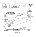
- FIGURE 6 describes a system for generating ultrasonic displacements at a remote target utilizing a laser with tunable wavelength in temporal shape.
- System 100 or other embodiments of the present invention as illustrated in FIGUREs 2, 3 and 4, may be utilized to generate a laser having tunable wavelength and temporal shape.
- This laser may be applied by a fiber optic carrier 21 to a remote target 102.
- a material such as ZBLAN, or Ag:Br glass may be selected for optical carrier 21.
- a long pulse may be encoded into laser 20 by encoding the long pulse prior to shifting from a first wavelength of laser 12 to a second wavelength of laser 16.
- This long pulse may be dynamically controlled by a computer system 26 in order to alter an inspection acoustic frequency or a depth of inspection.
- These encoded pulses may include a tome burst or chirp to control the inspection acoustic frequency. The need to dynamically control this long pulse might arise from different polymers in a composite or different thicknesses in different regions of remote
- a detection laser 104 may be applied to the remote target 102. In one embodiment (not shown), this detection laser 104 may be applied coaxially with generation laser 20.
- Generation laser 20 produces a compressional ultrasonic displacement in the material of target 102. The ultrasonic displacement is a result of thermo-elastic expansion of the material of target 102 as it absorbs generation laser 20.
- Generation laser 20 must be of a frequency that is readily absorbed at the desired depth in remote target 102 without causing ablation or damage to the material of target 102. Furthermore, generation laser 20 must be of a long enough pulse to induce ultrasonic deformations. Generation laser 20 should be absorbed into remote target 102 as heat, thereby causing thermo-elastic expansion without ablation.
- Detection laser 104 must be of a frequency that does not induce further ultrasonic displacements at remote target 102.
- Detection laser 104 interacts with ultrasonic displacements at remote target 102 and produces phase-modulated light 106. Some of the phase-modulated light 106 may be captured by collection optics 108.
- Methods for detecting such ultrasonic displacements are disclosed in U.S. Patent Application Serial No. 09/345,558, entitled “Method and Apparatus For Detecting Ultrasonic Surface Displacements Using Post-Collection Optical Implementation,” filed on June 29, 1999, to Thomas E. Drake, and U.S. Patent Application Serial No. 09/343,920, entitled “Method and Apparatus For Ultrasonic Laser Testing,” filed on June 29, 1999, to Thomas E. Drake. These patent applications are hereby incorporated by reference.
- the present invention provides an important technical advantage in that a laser-generated ultrasonic wave can be generated with a desired frequency content and temporal shape.
- optimal ultrasonic displacements may be generated by a laser having optimal optical characteristics.
- An optimal wavelength ⁇ 1 for generation laser 20 may be determined.
- generation laser 20 may be used to generate the desired ultrasonic displacements at a remote target to be inspected.
- the desired ultrasonic displacements can be generated and in turn produce increased resolution for target inspection.
- inspection scanning of a remote target can be optimized based on the attenuation characteristics of the ultrasonic displacements generated at the remote target. Although this enhances and optimizes the efficiency of the non-destructive evaluation testing of materials, this reduces costs and inspection time associated with these materials.
Landscapes
- Physics & Mathematics (AREA)
- General Physics & Mathematics (AREA)
- Immunology (AREA)
- General Health & Medical Sciences (AREA)
- Pathology (AREA)
- Health & Medical Sciences (AREA)
- Life Sciences & Earth Sciences (AREA)
- Chemical & Material Sciences (AREA)
- Analytical Chemistry (AREA)
- Biochemistry (AREA)
- Engineering & Computer Science (AREA)
- Optics & Photonics (AREA)
- Acoustics & Sound (AREA)
- Multimedia (AREA)
- Signal Processing (AREA)
- Investigating Or Analyzing Materials By The Use Of Ultrasonic Waves (AREA)
- Optical Modulation, Optical Deflection, Nonlinear Optics, Optical Demodulation, Optical Logic Elements (AREA)
- Lasers (AREA)
- Optical Radar Systems And Details Thereof (AREA)
Claims (22)
- Verfahren zur Erzeugung von Ultraschallverlagerungen an einem entfernten Ziel (102), das folgende Schritte enthält: Erzeugen eines Laserstrahls (12) von Pulsen mit einer ersten bekannten Wellenlänge (λ0), Richten des Laserstrahls (12) auf einen Punkt auf dem entfernten Ziel (102) zur Erzeugung von Ultraschallverlagerungen auf dem entfernten Ziel (102), Erfassen der Ultraschallverlagerungen auf dem entfernten Ziel (102) gekennzeichnet durch gesteuertes Verschieben der ersten bekannten Wellenlänge (λ0) des Laserstrahls (12) zu einer zweiten Wellenlänge (λ1) im Bereich von 1000 - 4000 nm zur Änderung der Ultraschallverschiebung, die an dem entfernten Ziel (102) durch den Laserstrahl (12) auftritt, um eine optimale Auflösung der Ultraschallverschiebung während der Erfassung zu erreichen.
- Verfahren nach Anspruch 1, das ferner den Schritt der Modulation der zweiten Wellenlänge (λ1) des Laserstrahls (12) enthält, um die Charakteristika der Ultraschallverlagerungen zu ändern.
- Verfahren nach Anspruch 2, das weiter den Schritt der Filterung des Laserstrahls (12) vor der Modulation der zweiten Wellenlänge (λ1) des Laserstrahls enthält, um ein Signal-Rausch-Verhältnis des Laserstrahls zu verbessern.
- Verfahren nach einem der Ansprüche 1 - 3, das weiter den Schritt der Modulation der Amplitude des Laserstrahls (12) aufweist, um die Charakteristika der Ultraschallverlagerungen zu ändern.
- Verfahren nach einem der Ansprüche 1 - 4, bei dem der Schritt der gesteuerten Verschiebung der ersten bekannten Wellenlänge (λ0) des Laserstrahls (12) auf eine zweite Wellenlänge (λ1) durch einen optischen parametrischen Oszillator realisiert wird.
- Verfahren nach einem der Ansprüche 1 - 4, bei dem der Schritt der gesteuerten Verschiebung der ersten bekannten Wellenlänge (λ0) des Laserstrahls (12) auf die zweite Wellenlänge (λ1) durch eine Kombination des Laserstrahls (12) mit einem zweiten Laserstrahl (24) realisiert wird, um einen neuen Laserstrahl an der zweiten Wellenlänge (λ1) zu erzeugen.
- Verfahren nach einem der vorhergehenden Ansprüche, bei dem die zweite Wellenlänge (λ1) kompatibel mit einer flexiblen optischen Leitung (21) ist.
- Verfahren nach einem der vorhergehenden Ansprüche, das weiter den Schritt der Encodierung eines langen Quelllaserpulses enthält, bevor die erste Wellenlänge (λ0) des Laserstrahls (12) zur zweiten Wellenlänge (λ1) gesteuert verschoben wird.
- Verfahren nach Anspruch 8, bei dem der Schritt des Encodierens des langen Quelllaserpulses durch ein Computersystem (26) dynamisch gesteuert wird.
- Verfahren nach Anspruch 9, bei dem der lange Quelllaserpuls mit einer Tonsignalfolge encodiert wird.
- Verfahren nach einem der vorhergehenden Ansprüche, bei dem der Laserstrahl (12) eine Wiederholungsrate von > als 400 Hz aufweist.
- Verfahren nach einem der vorhergehenden Ansprüche, bei dem der Laserstrahl (12) durch einen Laser (10) erzeugt wird, der aus der Gruppe ausgewählt wird, die aus CO2-Laser, Nd:YAG-Laser. Alexandrite-Laser, Titanium-Saphir-Laser, lampengepumpter Laser und diodengepumpter Laser besteht.
- System zur Erzeugung von Ultraschallverlagerungen auf einem entfernten Ziel (102), bei dem das System Folgendes enthält: einen Laser (10) zur Erzeugung eines gepulsten Laserstrahls (12) mit einer ersten bekannten Wellenlänge (λ0), eine Laserstrahlrichteinrichtung zur Leitung des Laserstrahls (12) auf einen Punkt auf einem entfernten Ziel (102), einem Ultraschallverlagerungssensor (104) zur Erfassung von Ultraschallverlagerungen auf dem entfernten Ziel (102), gekennzeichnet durch eine Wellenlängeverschiebeeinheit (14) zur gesteuerten Verschiebung der ersten bekannten Wellenlänge (λ0) des Laserstrahls (12) auf eine zweite Wellenlänge (λ1) im Bereich von 1000 - 4000 nm zur Erzeugung einer optimalen Auflösung der Ultraschallverlagerungen für den Ultraschallverlagerungssensor (104).
- System nach Anspruch 13, das ferner einen Modulator enthält zur Modulation der zweiten Wellenlänge (λ1) des Laserstrahls (12) zur Änderung der Charakteristika der Ultraschallverlagerungen.
- System nach Anspruch 14, das ferner einen optischen Filter zur Filterung des Laserstrahls (12) vor der Modulation der zweiten Wellenlänge (λ1) des Laserstrahls (12) enthält, um ein Signal/Rausch-Verhältnis des Laserstrahls (12) zu verbessern.
- System nach einem der Ansprüche 13 - 15, das ferner einen Modulator zur Modulation der Amplitude des Laserstrahls (12) zur Änderung der Charakteristika der Ultraschallverlagerungen enthält.
- System nach einem der Ansprüche 13 - 16, bei dem die Einrichtung zur Verschiebung der Wellenlänge (40) ein optischer parametrischer Oszillator ist.
- System nach einem der Ansprüche 13 - 16, bei dem die Einrichtung (14) zur Verschiebung der Wellenlänge den Laserstrahl (12) mit einem zweiten Laserstrahl (24) kombiniert, um einen neuen Laserstrahl bei der zweiten Wellenlänge (λ1) zu erzeugen.
- System nach einem der Ansprüche 13 - 18, bei dem die zweite Wellenlänge (λ1) mit einer flexiblen optischen Leitung kompatibel ist.
- System nach einem der Ansprüche 13 - 19, das ferner einen Encoder aufweist, um einen langen Quelllaserpuls vor der gesteuerte Verschiebung der ersten Wellenlänge (λ0) des Laserstrahls (12) zur zweiten Wellenlänge (λ1) zur encodieren.
- System nach Anspruch 20, das ferner ein Computersystem (26) zur dynamischen Steuerung des Encoders enthält
- System nach einem der Ansprüche 13 - 21, bei dem der Laser (10) aus der Gruppe ausgewählt ist, die aus CO2-Laser, Nd:YAG-Laser, Alexandrite-Laser, Titanium-Saphir-Laser, gepumpte Dioden- und lampengepumpter Laser besteht.
Applications Claiming Priority (3)
| Application Number | Priority Date | Filing Date | Title |
|---|---|---|---|
| US09/361,769 US6335943B1 (en) | 1999-07-27 | 1999-07-27 | System and method for ultrasonic laser testing using a laser source to generate ultrasound having a tunable wavelength |
| US361769 | 1999-07-27 | ||
| PCT/US2000/020403 WO2001007865A2 (en) | 1999-07-27 | 2000-07-27 | System and method for ultrasonic laser testing using a laser source to generate ultrasound having a tunable wavelength |
Publications (2)
| Publication Number | Publication Date |
|---|---|
| EP1228501A2 EP1228501A2 (de) | 2002-08-07 |
| EP1228501B1 true EP1228501B1 (de) | 2005-12-14 |
Family
ID=23423381
Family Applications (1)
| Application Number | Title | Priority Date | Filing Date |
|---|---|---|---|
| EP00968312A Expired - Lifetime EP1228501B1 (de) | 1999-07-27 | 2000-07-27 | System und verfahren zur ultraschall-laseruntersuchung mit einem laser abstimmbarer wellenlänge zur ultraschallerzeugung |
Country Status (10)
| Country | Link |
|---|---|
| US (1) | US6335943B1 (de) |
| EP (1) | EP1228501B1 (de) |
| JP (1) | JP2003508771A (de) |
| KR (1) | KR20020034995A (de) |
| AT (1) | ATE313144T1 (de) |
| AU (1) | AU768188B2 (de) |
| CA (1) | CA2363928C (de) |
| DE (1) | DE60024863T2 (de) |
| TW (1) | TW451055B (de) |
| WO (1) | WO2001007865A2 (de) |
Cited By (2)
| Publication number | Priority date | Publication date | Assignee | Title |
|---|---|---|---|---|
| TWI468663B (zh) * | 2008-05-15 | 2015-01-11 | Lockheed Corp | 使用co2雷射及諧波產生以產生超音波之改良中紅外線雷射及超音波偵測系統 |
| WO2018208886A1 (en) * | 2017-05-10 | 2018-11-15 | General Electric Company | Ultrasonic inspection methods and systems |
Families Citing this family (44)
| Publication number | Priority date | Publication date | Assignee | Title |
|---|---|---|---|---|
| US6813951B2 (en) * | 2000-07-13 | 2004-11-09 | National Research Council Of Canada | Laser-ultrasonic testing system |
| AU2007200013B2 (en) * | 2000-07-14 | 2010-01-21 | Lockheed Martin Corporation | System and method for locating and positioning an ultrasonic signal generator for testing purposes |
| EP1311874B1 (de) * | 2000-07-14 | 2012-05-23 | Lockheed Martin Corporation | Laser-Ultraschall-Prüfungssystem und Lokalisierungsmechanismus dafür |
| US6668654B2 (en) * | 2001-08-15 | 2003-12-30 | Lockheed Martin Corporation | Method and apparatus for generating specific frequency response for ultrasound testing |
| US7117134B2 (en) * | 2001-10-18 | 2006-10-03 | Lockheed Martin Corporation | Method to optimize generation of ultrasound using mathematical modeling for laser ultrasound inspection |
| US7370532B2 (en) * | 2002-01-11 | 2008-05-13 | Lockheed Martin Corporation | RF communications method and system for laser ultrasonic testing |
| US6945114B2 (en) | 2002-11-25 | 2005-09-20 | The Johns Hopkins University | Laser-air, hybrid, ultrasonic testing of railroad tracks |
| US6862936B2 (en) * | 2002-11-27 | 2005-03-08 | The Johns Hopkins University | Laser-air, hybrid, ultrasonic testing of railroad wheels |
| US20060187533A1 (en) * | 2003-03-07 | 2006-08-24 | Tim Nielsen | Method and device for time-gated amplification of photons |
| US7791739B2 (en) * | 2004-04-20 | 2010-09-07 | Lockheed Martin Corporation | System and method to enable eye-safe laser ultrasound detection |
| US7612894B2 (en) * | 2006-07-18 | 2009-11-03 | Lockheed Martin Corporation | Fiber laser for ultrasonic testing |
| US7800762B2 (en) * | 2006-09-20 | 2010-09-21 | Lockheed Martin Corporation | Fiber-based mid-infrared generation laser for laser ultrasound inspection |
| KR100943710B1 (ko) * | 2007-11-15 | 2010-02-23 | 한국표준과학연구원 | 다중화 광섬유 브래그 격자 센싱 시스템 및 그 방법 |
| US8054470B2 (en) * | 2008-05-15 | 2011-11-08 | Lockheed Martin Corporation | Method and apparatus for spectroscopic characterization of samples using a laser-ultrasound system |
| US8064488B2 (en) * | 2008-05-15 | 2011-11-22 | Lockheed Martin Corporation | Mid-IR laser for generation of ultrasound |
| US7821646B2 (en) * | 2008-05-15 | 2010-10-26 | Lockheed Martin Corporation | Method and apparatus for generating mid-IR laser beam for ultrasound inspection |
| US20090287427A1 (en) * | 2008-05-16 | 2009-11-19 | Lockheed Martin Corporation | Vision system and method for mapping of ultrasonic data into cad space |
| US8243280B2 (en) * | 2008-05-20 | 2012-08-14 | Iphoton Solutions, Llc | Laser ultrasonic measurement system with movable beam delivery |
| KR101091566B1 (ko) | 2009-04-29 | 2011-12-13 | 한국원자력연구원 | 고반복 극초단 레이저를 이용한 초음파 측정장치 |
| JP5570451B2 (ja) * | 2010-02-16 | 2014-08-13 | パナソニック株式会社 | レーザ溶接装置およびレーザ溶接方法 |
| JP5249975B2 (ja) * | 2010-02-26 | 2013-07-31 | 三菱重工業株式会社 | レーザ超音波探傷装置 |
| WO2012019189A2 (en) | 2010-08-06 | 2012-02-09 | Par Systems, Inc. | Containerized systems |
| US9999354B2 (en) * | 2011-01-21 | 2018-06-19 | National Research Council Of Canada | Biological tissue inspection method and system |
| US8661874B2 (en) * | 2011-04-28 | 2014-03-04 | Honeywell International Inc. | Photoacoustic detector with background signal correction |
| EP2565673B1 (de) * | 2011-09-05 | 2013-11-13 | ALLTEC Angewandte Laserlicht Technologie Gesellschaft mit beschränkter Haftung | Vorrichtung und Verfahren zum Markieren eines Objekts mit Hilfe eines Laserstrahls |
| EP2565998A1 (de) | 2011-09-05 | 2013-03-06 | ALLTEC Angewandte Laserlicht Technologie Gesellschaft mit beschränkter Haftung | Gasringlaservorrichtung |
| EP2564970B1 (de) | 2011-09-05 | 2015-08-26 | ALLTEC Angewandte Laserlicht Technologie Gesellschaft mit beschränkter Haftung | Markierungsvorrichtung zum Markieren eines Gegenstands mit einem Markierungslicht mit verschiedenen Licht-Modulen von unterschiedlichen Technologien |
| EP2565995B1 (de) | 2011-09-05 | 2013-12-18 | ALLTEC Angewandte Laserlicht Technologie Gesellschaft mit beschränkter Haftung | Gaslaservorrichtung mit Gasreservoir |
| ES2452529T3 (es) | 2011-09-05 | 2014-04-01 | ALLTEC Angewandte Laserlicht Technologie Gesellschaft mit beschränkter Haftung | Dispositivo láser y procedimiento para marcar un objeto |
| ES2450467T3 (es) | 2011-09-05 | 2014-03-24 | ALLTEC Angewandte Laserlicht Technologie Gesellschaft mit beschränkter Haftung | Dispositivo láser y procedimiento de generación de luz láser |
| EP2564974B1 (de) | 2011-09-05 | 2015-06-17 | ALLTEC Angewandte Laserlicht Technologie Gesellschaft mit beschränkter Haftung | Markierungsvorrichtung mit mehreren Resonatorröhren aufweisenden Gas-Lasern und einzel justierbaren Deflektoren |
| DK2564973T3 (en) | 2011-09-05 | 2015-01-12 | Alltec Angewandte Laserlicht Technologie Ges Mit Beschränkter Haftung | Marking apparatus having a plurality of lasers and a kombineringsafbøjningsindretning |
| ES2530070T3 (es) | 2011-09-05 | 2015-02-26 | ALLTEC Angewandte Laserlicht Technologie Gesellschaft mit beschränkter Haftung | Aparato de marcado con una pluralidad de láseres y conjuntos ajustables individualmente de medios de desviación |
| EP2564971B1 (de) | 2011-09-05 | 2015-08-26 | ALLTEC Angewandte Laserlicht Technologie Gesellschaft mit beschränkter Haftung | Markierungsvorrichtung mit mehreren Lasern und einem Satz von Reflektoren |
| EP2565996B1 (de) | 2011-09-05 | 2013-12-11 | ALLTEC Angewandte Laserlicht Technologie Gesellschaft mit beschränkter Haftung | Lasergerät mit Lasereinheit und Flüssigkeitsbehälter für eine Kühlvorrichtung dieser Lasereinheit |
| EP2564976B1 (de) | 2011-09-05 | 2015-06-10 | ALLTEC Angewandte Laserlicht Technologie Gesellschaft mit beschränkter Haftung | Markierungsvorrichtung mit mindestens einem Gaslaser und einer Kühleinrichtung |
| EP2564972B1 (de) | 2011-09-05 | 2015-08-26 | ALLTEC Angewandte Laserlicht Technologie Gesellschaft mit beschränkter Haftung | Markierungsvorrichtung mith mehreren Lasern, Deflektionmitteln und Telescopikmitteln für jeden Laserstrahl |
| US8976446B2 (en) | 2012-06-19 | 2015-03-10 | Bae Systems Information And Electronic Systems Integration Inc. | Efficient extended shift monolithic raman fiber laser |
| KR101700139B1 (ko) | 2014-02-27 | 2017-02-13 | 한국원자력연구원 | 레이저 기반 비선형인자 측정 장치 및 방법 |
| CN106338423B (zh) | 2015-07-10 | 2020-07-14 | 三斯坎公司 | 组织学染色的空间复用 |
| US10942152B2 (en) * | 2016-06-21 | 2021-03-09 | Shimadzu Corporation | Defect inspection device and method |
| CN115997324B (zh) | 2020-08-31 | 2025-03-21 | 极光先进雷射株式会社 | 激光装置、波长控制方法和电子器件的制造方法 |
| CN113628607B (zh) * | 2021-08-05 | 2023-07-18 | 青岛大学 | 一种声学天线及其应用 |
| KR102813892B1 (ko) * | 2021-11-05 | 2025-05-28 | 한국전자기술연구원 | 셀의 기공 구조 분석 장치, 시스템 및 방법 |
Family Cites Families (4)
| Publication number | Priority date | Publication date | Assignee | Title |
|---|---|---|---|---|
| JPH0731112B2 (ja) | 1986-08-11 | 1995-04-10 | 株式会社日立製作所 | 粒子状物質の検出方法およびその装置 |
| US5900533A (en) | 1995-08-03 | 1999-05-04 | Trw Inc. | System and method for isotope ratio analysis and gas detection by photoacoustics |
| US5608166A (en) | 1995-10-12 | 1997-03-04 | National Research Council Of Canada | Generation and detection of ultrasound with long pulse lasers |
| US6122060A (en) * | 1998-06-30 | 2000-09-19 | Lockheed Martin Corporation | Method and apparatus for detecting ultrasonic surface displacements using post-collection optical amplification |
-
1999
- 1999-07-27 US US09/361,769 patent/US6335943B1/en not_active Expired - Lifetime
-
2000
- 2000-07-26 TW TW089114965A patent/TW451055B/zh not_active IP Right Cessation
- 2000-07-27 WO PCT/US2000/020403 patent/WO2001007865A2/en not_active Ceased
- 2000-07-27 EP EP00968312A patent/EP1228501B1/de not_active Expired - Lifetime
- 2000-07-27 AU AU78248/00A patent/AU768188B2/en not_active Ceased
- 2000-07-27 DE DE60024863T patent/DE60024863T2/de not_active Expired - Lifetime
- 2000-07-27 CA CA002363928A patent/CA2363928C/en not_active Expired - Fee Related
- 2000-07-27 JP JP2001521962A patent/JP2003508771A/ja active Pending
- 2000-07-27 KR KR1020017014797A patent/KR20020034995A/ko not_active Ceased
- 2000-07-27 AT AT00968312T patent/ATE313144T1/de not_active IP Right Cessation
Cited By (3)
| Publication number | Priority date | Publication date | Assignee | Title |
|---|---|---|---|---|
| TWI468663B (zh) * | 2008-05-15 | 2015-01-11 | Lockheed Corp | 使用co2雷射及諧波產生以產生超音波之改良中紅外線雷射及超音波偵測系統 |
| WO2018208886A1 (en) * | 2017-05-10 | 2018-11-15 | General Electric Company | Ultrasonic inspection methods and systems |
| US10620162B2 (en) | 2017-05-10 | 2020-04-14 | Baker Hughes, A Ge Company, Llc | Ultrasonic inspection methods and systems |
Also Published As
| Publication number | Publication date |
|---|---|
| AU768188B2 (en) | 2003-12-04 |
| WO2001007865A3 (en) | 2001-05-25 |
| DE60024863T2 (de) | 2006-08-24 |
| CA2363928C (en) | 2005-03-22 |
| EP1228501A2 (de) | 2002-08-07 |
| TW451055B (en) | 2001-08-21 |
| CA2363928A1 (en) | 2001-02-01 |
| ATE313144T1 (de) | 2005-12-15 |
| KR20020034995A (ko) | 2002-05-09 |
| US6335943B1 (en) | 2002-01-01 |
| JP2003508771A (ja) | 2003-03-04 |
| WO2001007865A2 (en) | 2001-02-01 |
| AU7824800A (en) | 2001-02-13 |
| DE60024863D1 (de) | 2006-01-19 |
Similar Documents
| Publication | Publication Date | Title |
|---|---|---|
| US6335943B1 (en) | System and method for ultrasonic laser testing using a laser source to generate ultrasound having a tunable wavelength | |
| US7684047B2 (en) | Apparatus and method for two wave mixing (TWM) based ultrasonic laser testing | |
| US6684701B2 (en) | System and method of determining porosity in composite materials using ultrasound | |
| JP4386709B2 (ja) | レーザ超音波による材料非破壊検査方法及び装置 | |
| WO1980001005A1 (en) | Photoacoustic or thermoacoustic microscopy | |
| McKie et al. | Practical considerations for the rapid inspection of composite materials using laser-based ultrasound | |
| CA2379279C (en) | Device and method for laser-ultrasonic frequency control using optimal wavelength tuning | |
| AU2002245195B2 (en) | Method and apparatus for improving the dynamic range of laser detected ultrasonic in attenuative materials | |
| US7561281B2 (en) | System and method for controlling tube thickness | |
| JP2001208729A (ja) | 欠陥検出装置 | |
| US7545509B2 (en) | System and method for online control of paper elasticity and thickness | |
| CA2489714C (en) | System and method for ultrasonic laser testing using a laser source to generate ultrasound having a tunable wavelength | |
| Caron et al. | Gas coupled laser acoustic detection for ultrasound inspection of composite materials | |
| JPH0933490A (ja) | 非接触非破壊材料評価方法及び装置 | |
| Caron et al. | Overview: Ultrasound sensing using gas-coupled laser acoustic detection | |
| CN121164436A (zh) | 基于光栅激光超声的增材制造过程在线检测系统及方法 | |
| Campagne et al. | Laser‐Ultrasonic Characterization of Fiber Reinforced Composites: Effect of the Generation Laser Transverse Modes | |
| Djordjevic et al. | Guided wave non-contact ultrasonic for NDE | |
| Blouin et al. | Laser ultrasonics: a new tool for the industry | |
| Ochiai et al. | Sizing of small surface-breaking tight cracks by using laser-ultrasonics | |
| Crostack et al. | Non-destructive testing of arc and plasma sprayed coatings by ultrasonic imaging technique | |
| Kessler | Introduction to Acoustic Microscopy Techniques |
Legal Events
| Date | Code | Title | Description |
|---|---|---|---|
| PUAI | Public reference made under article 153(3) epc to a published international application that has entered the european phase |
Free format text: ORIGINAL CODE: 0009012 |
|
| 17P | Request for examination filed |
Effective date: 20020108 |
|
| AK | Designated contracting states |
Kind code of ref document: A2 Designated state(s): AT BE CH CY DE DK ES FI FR GB GR IE IT LI LU MC NL PT SE |
|
| AX | Request for extension of the european patent |
Free format text: AL PAYMENT 20020108;LT PAYMENT 20020108;LV PAYMENT 20020108;MK PAYMENT 20020108;RO PAYMENT 20020108;SI PAYMENT 20020108 |
|
| RIN1 | Information on inventor provided before grant (corrected) |
Inventor name: LORRAINE, PETER, W. Inventor name: FILKINS, ROBERT, J. Inventor name: BIGIO, LAURENCE |
|
| 17Q | First examination report despatched |
Effective date: 20031017 |
|
| GRAP | Despatch of communication of intention to grant a patent |
Free format text: ORIGINAL CODE: EPIDOSNIGR1 |
|
| GRAS | Grant fee paid |
Free format text: ORIGINAL CODE: EPIDOSNIGR3 |
|
| GRAA | (expected) grant |
Free format text: ORIGINAL CODE: 0009210 |
|
| AK | Designated contracting states |
Kind code of ref document: B1 Designated state(s): AT BE CH CY DE DK ES FI FR GB GR IE IT LI LU MC NL PT SE |
|
| AX | Request for extension of the european patent |
Extension state: AL LT LV MK RO SI |
|
| PG25 | Lapsed in a contracting state [announced via postgrant information from national office to epo] |
Ref country code: AT Free format text: LAPSE BECAUSE OF FAILURE TO SUBMIT A TRANSLATION OF THE DESCRIPTION OR TO PAY THE FEE WITHIN THE PRESCRIBED TIME-LIMIT Effective date: 20051214 Ref country code: LI Free format text: LAPSE BECAUSE OF FAILURE TO SUBMIT A TRANSLATION OF THE DESCRIPTION OR TO PAY THE FEE WITHIN THE PRESCRIBED TIME-LIMIT Effective date: 20051214 Ref country code: NL Free format text: LAPSE BECAUSE OF FAILURE TO SUBMIT A TRANSLATION OF THE DESCRIPTION OR TO PAY THE FEE WITHIN THE PRESCRIBED TIME-LIMIT Effective date: 20051214 Ref country code: FI Free format text: LAPSE BECAUSE OF FAILURE TO SUBMIT A TRANSLATION OF THE DESCRIPTION OR TO PAY THE FEE WITHIN THE PRESCRIBED TIME-LIMIT Effective date: 20051214 Ref country code: CH Free format text: LAPSE BECAUSE OF FAILURE TO SUBMIT A TRANSLATION OF THE DESCRIPTION OR TO PAY THE FEE WITHIN THE PRESCRIBED TIME-LIMIT Effective date: 20051214 Ref country code: BE Free format text: LAPSE BECAUSE OF FAILURE TO SUBMIT A TRANSLATION OF THE DESCRIPTION OR TO PAY THE FEE WITHIN THE PRESCRIBED TIME-LIMIT Effective date: 20051214 |
|
| REG | Reference to a national code |
Ref country code: GB Ref legal event code: FG4D |
|
| REG | Reference to a national code |
Ref country code: CH Ref legal event code: EP |
|
| REG | Reference to a national code |
Ref country code: IE Ref legal event code: FG4D |
|
| REF | Corresponds to: |
Ref document number: 60024863 Country of ref document: DE Date of ref document: 20060119 Kind code of ref document: P |
|
| PG25 | Lapsed in a contracting state [announced via postgrant information from national office to epo] |
Ref country code: SE Free format text: LAPSE BECAUSE OF FAILURE TO SUBMIT A TRANSLATION OF THE DESCRIPTION OR TO PAY THE FEE WITHIN THE PRESCRIBED TIME-LIMIT Effective date: 20060314 Ref country code: GR Free format text: LAPSE BECAUSE OF FAILURE TO SUBMIT A TRANSLATION OF THE DESCRIPTION OR TO PAY THE FEE WITHIN THE PRESCRIBED TIME-LIMIT Effective date: 20060314 Ref country code: DK Free format text: LAPSE BECAUSE OF FAILURE TO SUBMIT A TRANSLATION OF THE DESCRIPTION OR TO PAY THE FEE WITHIN THE PRESCRIBED TIME-LIMIT Effective date: 20060314 |
|
| PG25 | Lapsed in a contracting state [announced via postgrant information from national office to epo] |
Ref country code: ES Free format text: LAPSE BECAUSE OF FAILURE TO SUBMIT A TRANSLATION OF THE DESCRIPTION OR TO PAY THE FEE WITHIN THE PRESCRIBED TIME-LIMIT Effective date: 20060325 |
|
| PG25 | Lapsed in a contracting state [announced via postgrant information from national office to epo] |
Ref country code: PT Free format text: LAPSE BECAUSE OF FAILURE TO SUBMIT A TRANSLATION OF THE DESCRIPTION OR TO PAY THE FEE WITHIN THE PRESCRIBED TIME-LIMIT Effective date: 20060515 |
|
| LTIE | Lt: invalidation of european patent or patent extension |
Effective date: 20051214 |
|
| NLV1 | Nl: lapsed or annulled due to failure to fulfill the requirements of art. 29p and 29m of the patents act | ||
| REG | Reference to a national code |
Ref country code: CH Ref legal event code: PL |
|
| PG25 | Lapsed in a contracting state [announced via postgrant information from national office to epo] |
Ref country code: IE Free format text: LAPSE BECAUSE OF NON-PAYMENT OF DUE FEES Effective date: 20060727 |
|
| PG25 | Lapsed in a contracting state [announced via postgrant information from national office to epo] |
Ref country code: MC Free format text: LAPSE BECAUSE OF NON-PAYMENT OF DUE FEES Effective date: 20060731 |
|
| ET | Fr: translation filed | ||
| PLBE | No opposition filed within time limit |
Free format text: ORIGINAL CODE: 0009261 |
|
| STAA | Information on the status of an ep patent application or granted ep patent |
Free format text: STATUS: NO OPPOSITION FILED WITHIN TIME LIMIT |
|
| 26N | No opposition filed |
Effective date: 20060915 |
|
| REG | Reference to a national code |
Ref country code: IE Ref legal event code: MM4A |
|
| PG25 | Lapsed in a contracting state [announced via postgrant information from national office to epo] |
Ref country code: LU Free format text: LAPSE BECAUSE OF NON-PAYMENT OF DUE FEES Effective date: 20060727 |
|
| PG25 | Lapsed in a contracting state [announced via postgrant information from national office to epo] |
Ref country code: CY Free format text: LAPSE BECAUSE OF FAILURE TO SUBMIT A TRANSLATION OF THE DESCRIPTION OR TO PAY THE FEE WITHIN THE PRESCRIBED TIME-LIMIT Effective date: 20051214 |
|
| REG | Reference to a national code |
Ref country code: FR Ref legal event code: PLFP Year of fee payment: 17 |
|
| PGFP | Annual fee paid to national office [announced via postgrant information from national office to epo] |
Ref country code: IT Payment date: 20160722 Year of fee payment: 17 Ref country code: GB Payment date: 20160727 Year of fee payment: 17 Ref country code: DE Payment date: 20160726 Year of fee payment: 17 |
|
| PGFP | Annual fee paid to national office [announced via postgrant information from national office to epo] |
Ref country code: FR Payment date: 20160726 Year of fee payment: 17 |
|
| REG | Reference to a national code |
Ref country code: DE Ref legal event code: R119 Ref document number: 60024863 Country of ref document: DE |
|
| GBPC | Gb: european patent ceased through non-payment of renewal fee |
Effective date: 20170727 |
|
| REG | Reference to a national code |
Ref country code: FR Ref legal event code: ST Effective date: 20180330 |
|
| PG25 | Lapsed in a contracting state [announced via postgrant information from national office to epo] |
Ref country code: GB Free format text: LAPSE BECAUSE OF NON-PAYMENT OF DUE FEES Effective date: 20170727 Ref country code: DE Free format text: LAPSE BECAUSE OF NON-PAYMENT OF DUE FEES Effective date: 20180201 |
|
| PG25 | Lapsed in a contracting state [announced via postgrant information from national office to epo] |
Ref country code: FR Free format text: LAPSE BECAUSE OF NON-PAYMENT OF DUE FEES Effective date: 20170731 |
|
| PG25 | Lapsed in a contracting state [announced via postgrant information from national office to epo] |
Ref country code: IT Free format text: LAPSE BECAUSE OF NON-PAYMENT OF DUE FEES Effective date: 20170727 |