EP1228683A2 - Moissoneuse batteuse avec un transporteur rotatif - Google Patents
Moissoneuse batteuse avec un transporteur rotatif Download PDFInfo
- Publication number
- EP1228683A2 EP1228683A2 EP02100451A EP02100451A EP1228683A2 EP 1228683 A2 EP1228683 A2 EP 1228683A2 EP 02100451 A EP02100451 A EP 02100451A EP 02100451 A EP02100451 A EP 02100451A EP 1228683 A2 EP1228683 A2 EP 1228683A2
- Authority
- EP
- European Patent Office
- Prior art keywords
- driver
- rotary body
- combine harvester
- rotating body
- drivers
- Prior art date
- Legal status (The legal status is an assumption and is not a legal conclusion. Google has not performed a legal analysis and makes no representation as to the accuracy of the status listed.)
- Granted
Links
- 239000002184 metal Substances 0.000 claims description 19
- 239000000969 carrier Substances 0.000 claims description 11
- 238000006243 chemical reaction Methods 0.000 claims 1
- 230000001960 triggered effect Effects 0.000 claims 1
- 239000000463 material Substances 0.000 description 11
- 238000003306 harvesting Methods 0.000 description 4
- 230000008901 benefit Effects 0.000 description 3
- 241001124569 Lycaenidae Species 0.000 description 2
- 238000012423 maintenance Methods 0.000 description 2
- 238000000926 separation method Methods 0.000 description 2
- 239000010902 straw Substances 0.000 description 2
- 238000004804 winding Methods 0.000 description 2
- 241000251169 Alopias vulpinus Species 0.000 description 1
- 241000282472 Canis lupus familiaris Species 0.000 description 1
- 210000001015 abdomen Anatomy 0.000 description 1
- 238000005299 abrasion Methods 0.000 description 1
- 238000005520 cutting process Methods 0.000 description 1
- 238000007373 indentation Methods 0.000 description 1
- 238000004519 manufacturing process Methods 0.000 description 1
- 238000000034 method Methods 0.000 description 1
- 238000002360 preparation method Methods 0.000 description 1
- 230000001737 promoting effect Effects 0.000 description 1
- 238000011084 recovery Methods 0.000 description 1
- 230000008439 repair process Effects 0.000 description 1
- 230000002441 reversible effect Effects 0.000 description 1
- 239000007787 solid Substances 0.000 description 1
- 230000009466 transformation Effects 0.000 description 1
Images

Classifications
-
- A—HUMAN NECESSITIES
- A01—AGRICULTURE; FORESTRY; ANIMAL HUSBANDRY; HUNTING; TRAPPING; FISHING
- A01F—PROCESSING OF HARVESTED PRODUCE; HAY OR STRAW PRESSES; DEVICES FOR STORING AGRICULTURAL OR HORTICULTURAL PRODUCE
- A01F12/00—Parts or details of threshing apparatus
- A01F12/30—Straw separators, i.e. straw walkers, for separating residual grain from the straw
- A01F12/305—Straw separators, i.e. straw walkers, for separating residual grain from the straw combined with additional grain extracting means
-
- A—HUMAN NECESSITIES
- A01—AGRICULTURE; FORESTRY; ANIMAL HUSBANDRY; HUNTING; TRAPPING; FISHING
- A01D—HARVESTING; MOWING
- A01D61/00—Elevators or conveyors for binders or combines
- A01D61/008—Elevators or conveyors for binders or combines for longitudinal conveying, especially for combines
Definitions
- the invention relates to a combine harvester and a rotary conveyor arranged above, which with a Rotational body and at least one driver is provided, the body of revolution being a substantially closed one Has outer surface and the driver inside the Rotational body eccentric with respect to its axis of rotation and is rotatably mounted and is radially movable by a Carrier guide extends attached to the rotating body is.
- the cross shaker can also be operated by a rotary conveyor with moveable and eccentrically mounted drivers replace, as is known from DE-C-1 904 406.
- a rotary conveyor with moveable and eccentrically mounted drivers replace, as is known from DE-C-1 904 406.
- the straw is used for thorough separation of the cases remaining grains loosened longer and more intensely. By tearing open the crop carpet can be heavier Escape crop parts through the gaps created.
- GB-A-612 962 there is one in a feeder Combine arranged rotary conveyor described that from a rotatable, circular-cylindrical body of rotation with eccentrically arranged carriers are built therein.
- the Fingers extend through driver guides on the Are arranged inside of the rotating body and penetrate slits in the rotating body.
- Rotary conveyors according to GB-A-612 962 may be the good caught between the slots and the driver guides.
- the rotary conveyor contains a rotary body at least one eccentrically mounted and radial to this movable carrier.
- the further description goes however from several carriers because this is the normal case. This comes in the radially inner position of the drivers free end of the driver under the outer surface of it area of the rotating body leading in the direction of rotation lie. That is, the drivers are behind the outer surface of the Rotary body retracted so that on the side of the Rotary conveyor at which the material to be conveyed is delivered, this is not taken as far. This will make it Material treated very gently. Lets be particularly advantageous such a rotary conveyor in a combine Use shakers.
- the rotation body preferably has in its transformation offset radially inwards and parallel to the longitudinal center axis running areas in which the driver guides are arranged. This eliminates the risk of winding Conveyed goods are reduced because the surface of the rotary conveyor has fewer protrusions. Between the radially inwards offset areas is the outer surface of the rotating body in a suitable manner, e.g. B. circular, curved and smooth.
- the shell of the rotating body is made of at least one Shaped metal cover that is curved so that the result in radially offset areas.
- the parallel to Edges of the metal cover running along the longitudinal center axis on the one located in the direction of rotation of the drum conveyor Shadow side of the inward shifted areas housed. This reduces the risk of the goods being conveyed to get caught. Is the surface of the rotating body with provided with several metal covers, it is in the case of Maintenance or repairs are sufficient, only the metal covers to solve that stand in the way of the maintenance process, so that the workload is reduced considerably.
- the drivers are rotatably mounted on stub shafts.
- a the stub shaft is in the drive flange of the rotating body stored. By screwing the drive flange with one of the end walls of the rotating body is the stub shaft thus automatically centered.
- the drivers are at intervals in the direction of the Rotation axis of the rotary conveyor arranged, in particular such that, starting with the first driver, three each Carriers form a group and successive carriers are offset from each other by 120 °.
- the distance consecutive carriers can, depending on the type of Use vary and, for example, when using above the shaker of a combine after the Straighten the width of the shaker.
- the rotary conveyor is installed above the shakers that a group of for example, three carriers.
- the drivers are eccentric and rotatable on one axis stored itself on stub shafts of the rotating body is stored. This causes the drivers to turn of the rotating body alternating about its longitudinal center axis retracted and extended and can thus convey the goods record and hand in, for example, underpowering above a combine harvester.
- a deflector plate to the Rotational body can be put.
- the Deflector plate can extend over the entire long side of the Rotate body or consist of strips that the material to be conveyed from the surface only between the carriers keep away from the rotating body. If the deflector plate is very is placed close to the drum, it can also tear off stalks, that get stuck on the drum. This advantage comes all the more the smaller the gap between Deflector plate and rotating body is.
- the deflector plate is pivotally mounted, e.g. B. in the frame of a harvesting vehicle, it can be caused by winding Material can be folded back and a switch actuate, which triggers a warning signal.
- the rotary conveyor can be arranged so that it both for overshot and undershot transportation of crop is suitable.
- the benefits come from sinking Projections such as B. the driver guides, equally effective as in the undershot Transport.
- FIG. 1 shows a harvesting machine 10 in the form of a Combine with front driven and rear steerable wheels 12 and 14 and a driver's cabin 16, of which from it can be operated by a driver.
- a combine could also be a stationary thresher, a trial threshing system or the like come into question.
- a grain tank closes to the rear of the driver's cab 16 18 to the goods delivered into it via an emptying pipe 20 can give up outside.
- the grain tank 18 is supported on a frame 22, in the supplied material on the way via a threshing drum 24, a concave 26 and a turning drum 28 in his large and small components is disassembled.
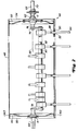
- shaker 30 is a transverse to the direction of travel arranged axis of rotation serving as an additional separator Rotary conveyor 42 with a rotating body 44 and Carriers 84, as shown in Figure 2, provided that There is metal or plastic.
- a deflector plate 8 is provided, which can be pivoted can.
- the rotation of the rotary conveyor 42 takes place with a view to Figure 1 counterclockwise, d. H. undershot promoting.
- This also includes drive means, not shown z. B. one with an end wall of the rotating body 44 non-rotatably connected pulley provided one of initiates an upcoming drive.
- the position of the rotary conveyor 42 is preferably - but not exclusively - above the Shaker 30 in the area of half its length. This position can be vertical as well by means of an appropriate guide be changed horizontally.
- the rotary conveyor 42 could also be used directly can be provided downstream of the turning drum 28.
- the drive means can be designed in a variety of ways be and z.
- the rotary conveyor 42 can both top and are also driven underpowering, whereby if necessary, the position of the driver 84 accordingly must be adjusted.
- Rotary conveyor 42 essentially the structure of the Center area of a screw conveyor of a cutting unit or corresponds to a pick-up that is well known.
- the rotary conveyor 42 contains one Rotating body 44, the outer surface of which is in the present Case composed of three metal covers 48.
- the Metal covers 48 are bent such that radially offset inside, parallel to the axis of rotation of the regions 46 extending in drum-shaped rotary conveyor 42 result in which in the embodiment shown eighteen radially inward extending plastic or Metal driver guides 50 and openings 52 are located.
- the parallel to the axis of rotation End edges of the metal covers 48 disappear into the radial inward offset areas 46.
- End walls 54 and 56 of the rotating body 44 are from Discs 58 and 60 formed, one with a Bearing flange 62 is provided, the hexagonal at six arranged points by means of screws 64 on the disk 58 is attached.
- the discs 58 and 60 are with the inside of two metal covers 48 of the rotating body 44 spot welded and have on the inside of the Rotating body 44 facing side pot-shaped indentations.
- the rotary body 44 is supported by stub shafts 66 and 68.
- the stub shaft 66 connected to the bearing flange 62 is provided with a keyway 70 for a gear.
- the rotating body 44 there is an eccentric and parallel to the axis of rotation of the rotating body 44 arranged bearing device, the two fixed stub shafts 68 and 74, two support arms 76 and 78 and an axis 80 contains. On the axis 80 are pivotable in two parts trained brackets 82 attached at intervals.
- the drivers 84 are solid as a straight and the same long bars with a circular cross-section in the example shown and predetermined breaking points 86 are formed, but can e.g. Belly be shaped and have to follow the direction of rotation not be massive in principle.
- the feet of the driver 84 are trained so that they in corresponding recesses of the Brackets 82 fit and are held there.
- the drivers 84 are arranged along the axis 80 so that them at a fixed angle, e.g. B. 120 °, offset from each other are and extend through the driver guides 50.
- the Drivers 84 are above openings 52 and Driver guides 50 in the rotating body 44 differ far beyond this to the outside.
- the axis 80 is by means of the support arms 76 and 78 with the Stub shafts 74 and 68 rigidly connected.
- the stub shaft 74 is rotatably mounted in the bearing flange 62 and the Stub shaft 68 becomes outside of the rotating body 44 set.
- Two roller bearings 4 and 6 are reached, that when rotating the rotating body 44 in one plane perpendicular to the longitudinal center axis 88, the discs 58 and 60 um the fixed stub shafts 68 and 74 rotate.
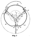
- the axis 80 maintains their position and the dogs 84 become during a revolution of the rotating body 44 over the Driver guides 50, which are laterally centered in the radial inwardly offset areas 46, one and extended.
- a driver 84 is located in the radial direction inside, then its free end is not radially offset under the outer surface of the jacket Area of the rotating body 44. The from the free ends of the Driver 84 described path is dashed in Figure 3 located.
- the driver guides 50 are in the offset Regions 46 of the rotating body 44 arranged and on two Places seen in the transverse direction to the longitudinal center axis 88 with the metal covers 48 on both sides of the openings 52 screwed or riveted.
- the metal covers 48 are next to each driver guide 50 with screws 90 together connected. Two of the three metal covers 48 are with the Washers 58 and 60 welded tight.
- the third Metal cover 48 can be removed by loosening screws 90 be completely removed.
- the screws 90 are on the lying in the direction of rotation of the rotating body 44 Shadow side of the radially inwardly offset regions 46 accommodated.
- metal covers 48 according to FIG. 2 and 3 has in addition to creating radially offset inwards Areas for the finger guides 50 and screw connections Advantage that the accessibility and assembly considerably simplified. For example, access to brackets 82 to enable, it is sufficient not to use the screw connections the washers 58 and 60 welded metal cover 48 in the Sink in which the finger guide 50 is located remove. The metal cover 48 then stands, as in the figure 3 shown using two settings, from the lateral surface from.
- the rotary body 44 can be inserted Set deflector plate 8, which is oriented so that at one Rotation of the rotating body 44 material to be conveyed, which is about the Has rotated body 44 is stripped.
- Combine harvesters 84 can be arranged so that they are in groups of three carriers 84 over one Shaker 30 are located, d. H. in a 5-shaker machine come fifteen and eighteen in a six-shaker machine Driver 84, as shown in Figure 2, for use.
- the three each in front of the end walls 54 and 56 of the Rotary body 44 located driver 84 have in this example a smaller distance from each other than that remaining carriers 84.
Landscapes
- Life Sciences & Earth Sciences (AREA)
- Environmental Sciences (AREA)
- Harvesting Machines For Root Crops (AREA)
- Threshing Machine Elements (AREA)
- Outside Dividers And Delivering Mechanisms For Harvesters (AREA)
- Harvester Elements (AREA)
Applications Claiming Priority (3)
| Application Number | Priority Date | Filing Date | Title |
|---|---|---|---|
| DE19803336A DE19803336A1 (de) | 1998-01-29 | 1998-01-29 | Rotationsförderer mit einem Rotationskörper und wenigstens einem Mitnehmer und Erntemaschine mit einem solchen Rotationsförderer |
| DE19803336 | 1998-01-29 | ||
| EP99100745A EP0933017B1 (fr) | 1998-01-29 | 1999-01-16 | Transporteur rotatif avec corps de rotation et au moins un entraíneur et récolteuse pourvue d'un tel transporteur rotatif |
Related Parent Applications (1)
| Application Number | Title | Priority Date | Filing Date |
|---|---|---|---|
| EP99100745A Division EP0933017B1 (fr) | 1998-01-29 | 1999-01-16 | Transporteur rotatif avec corps de rotation et au moins un entraíneur et récolteuse pourvue d'un tel transporteur rotatif |
Publications (3)
| Publication Number | Publication Date |
|---|---|
| EP1228683A2 true EP1228683A2 (fr) | 2002-08-07 |
| EP1228683A3 EP1228683A3 (fr) | 2002-09-18 |
| EP1228683B1 EP1228683B1 (fr) | 2004-08-18 |
Family
ID=7855961
Family Applications (2)
| Application Number | Title | Priority Date | Filing Date |
|---|---|---|---|
| EP02100451A Expired - Lifetime EP1228683B1 (fr) | 1998-01-29 | 1999-01-16 | Moissoneuse batteuse avec un transporteur rotatif |
| EP99100745A Expired - Lifetime EP0933017B1 (fr) | 1998-01-29 | 1999-01-16 | Transporteur rotatif avec corps de rotation et au moins un entraíneur et récolteuse pourvue d'un tel transporteur rotatif |
Family Applications After (1)
| Application Number | Title | Priority Date | Filing Date |
|---|---|---|---|
| EP99100745A Expired - Lifetime EP0933017B1 (fr) | 1998-01-29 | 1999-01-16 | Transporteur rotatif avec corps de rotation et au moins un entraíneur et récolteuse pourvue d'un tel transporteur rotatif |
Country Status (7)
| Country | Link |
|---|---|
| US (1) | US6244955B1 (fr) |
| EP (2) | EP1228683B1 (fr) |
| AR (1) | AR014520A1 (fr) |
| BR (1) | BR9900250A (fr) |
| CA (1) | CA2258300C (fr) |
| DE (4) | DE19803336A1 (fr) |
| DK (1) | DK0933017T3 (fr) |
Families Citing this family (24)
| Publication number | Priority date | Publication date | Assignee | Title |
|---|---|---|---|---|
| DE19920538A1 (de) * | 1999-05-05 | 2000-11-09 | Claas Selbstfahr Erntemasch | Erntemaschine |
| DE10042499A1 (de) * | 2000-08-30 | 2002-03-14 | Deere & Co | Rotationsförderer mit Fingern |
| US6668534B2 (en) | 2001-08-31 | 2003-12-30 | Deere & Company | Auger fingers for harvesting assemblies, and combines |
| FR2841378A1 (fr) | 2002-06-24 | 2003-12-26 | Thomson Plasma | Dalle de decharges coplanaires pour panneau de visualisation a plasma apportant une distribution de potentiel de surface adaptee |
| US7611445B2 (en) | 2004-01-05 | 2009-11-03 | Ab Coaster Holdings, Inc. | Abdominal exercise machine |
| DE102004013255B4 (de) * | 2004-03-18 | 2012-03-08 | Deere & Company | Mähdrescher mit einem Rotationsförderer |
| DE102004031054A1 (de) | 2004-06-25 | 2006-01-19 | Claas Selbstfahrende Erntemaschinen Gmbh | Schüttlerhilfe an einem Mähdrescher |
| DE102005016976A1 (de) * | 2005-04-13 | 2006-11-02 | Deere & Company, Moline | Mitnehmereinheit eines Rotationsförderers |
| US7401457B2 (en) * | 2005-08-01 | 2008-07-22 | Cnh America Llc | Auger finger with tether for retaining and retracting the finger when broken |
| US20070042822A1 (en) * | 2005-08-17 | 2007-02-22 | Lutz Bischoff | Combine with a rotary conveyor |
| US7426819B2 (en) * | 2006-10-06 | 2008-09-23 | Cnh America Llc | Auger finger with resilient elastomeric retainer retractor at breaking point |
| DE102007009313A1 (de) | 2007-02-22 | 2008-08-28 | Claas Selbstfahrende Erntemaschinen Gmbh | Landwirtschaftliche Arbeitsmaschine |
| US20080271427A1 (en) * | 2007-05-03 | 2008-11-06 | Stoffel Neal J | Horizontal rotary cutting system and method |
| EP2152058A1 (fr) * | 2007-06-04 | 2010-02-17 | Lord Corporation | Dispositif de rétention pour séparer des matériaux de doigt de vis haveuse de moissonneuse-batteuse et procédé d'enclenchement de matériau agricole |
| US20090056298A1 (en) * | 2007-08-28 | 2009-03-05 | Agco Corporation | Over-Retraction Limiter for the Fingers of a Retracting Finger Auger Mechanism |
| US20100212277A1 (en) * | 2009-02-20 | 2010-08-26 | Marrs William R | Crop harvester |
| BRPI0903650B1 (pt) * | 2009-09-17 | 2018-02-06 | Agco Do Brasil Máquinas E Equipamentos Agrícolas Ltda. | Dedo retrátil para montagem em um eixo principal de caracol de colheitadeiras de grãos |
| GB201319215D0 (en) * | 2013-10-31 | 2013-12-18 | Agco As | Grain seperating apparatus in a combine harvester |
| BE1022648B1 (nl) | 2015-03-24 | 2016-06-24 | Cnh Industrial Belgium Nv | Vijzelvingergeheel voor een oogstmachine |
| US9872436B2 (en) * | 2016-05-03 | 2018-01-23 | Deere & Company | Drum conveyor |
| CN107241971B (zh) * | 2017-07-14 | 2019-08-02 | 江苏大学 | 一种水稻联合收割机偏心切流初脱分离装置 |
| US20190200525A1 (en) * | 2017-12-29 | 2019-07-04 | Macdon Industries Ltd. | Retractable hollow finger for harvesting header |
| EP3603380A1 (fr) * | 2018-07-31 | 2020-02-05 | CNH Industrial Belgium N.V. | Trépan à doigts rétractables au dispositif d'alimentation d'une moissonneuse-batteuse |
| FR3090267B1 (fr) * | 2018-12-21 | 2021-04-09 | N V Depoortere | Roue de ramassage à doigts rétractables et déployables |
Family Cites Families (23)
| Publication number | Priority date | Publication date | Assignee | Title |
|---|---|---|---|---|
| DE8122977U1 (de) * | 1982-01-07 | Claas Ohg, 4834 Harsewinkel | Einzugswalze mit gesteuerten Einzugsfingern bei landwirtschaftlichen Erntemaschinen, insbesondere Mähdrescher | |
| US976306A (en) * | 1909-02-02 | 1910-11-22 | Gustave Sipler | Threshing-machine. |
| US1037248A (en) * | 1911-08-04 | 1912-09-03 | Paul Heinz | Grain-separator. |
| US1547476A (en) * | 1922-04-10 | 1925-07-28 | White Arthur William | Separating device for thrashing machines |
| DE567192C (de) | 1931-06-06 | 1932-12-29 | Buckau R Wolf Akt Ges Maschf | Reinigungsvorrichtung fuer die Rillen von Rillenwalzenrosten, bei der fuer jede Rille jeder Walze ein Raeumblatt vorgesehen ist und saemtliche Raeumblaetter auf einer zur Rostwelle parallelen Achse unterhalb derselben undrehbar angeordnet sind |
| GB612962A (en) * | 1946-06-11 | 1948-11-19 | Minneapolis Moline Power Co | Improvements in or relating to combine harvesters |
| US2557226A (en) * | 1949-03-15 | 1951-06-19 | Johnson John | Beater cylinder for combines and the like |
| US2670845A (en) * | 1950-06-30 | 1954-03-02 | Leonard W H Busack | Grain separating process and apparatus |
| DE1009842B (de) * | 1953-01-22 | 1957-06-06 | Fella Werke Gmbh | Foerdervorrichtung fuer Erntemaschinen |
| US2803505A (en) * | 1953-11-03 | 1957-08-20 | Allis Chalmers Mfg Co | Finger bearing retainer for feed cylinder |
| US2851144A (en) * | 1954-06-01 | 1958-09-09 | Massey Harris Ferguson Ltd | Conveyor for harvesters |
| DE1081711B (de) * | 1954-07-24 | 1960-05-12 | Massey Ferguson Gmbh | Zum Foerdern von halmartigem Erntegut bestimmte Foerderschnecke |
| US2849103A (en) * | 1955-07-25 | 1958-08-26 | Massey Ferguson Inc | Auger conveyor |
| NO116391B (fr) * | 1966-09-07 | 1969-03-17 | Claas Maschf Gmbh Geb | |
| DE2103981B2 (de) * | 1971-01-28 | 1974-02-28 | Deere & Co., Moline, Ill. (V.St.A.) | Oberhalb des Strohschüttlers von Dreschmaschinen und Mähdreschern angeordnete Vorrichtung zur Intensivierung der Restkörnerausscheidung |
| FR2315213A7 (fr) * | 1975-06-18 | 1977-01-14 | Taarup As Maskinfab | Machine pour ramasser et/ou recolter des produits agricoles, notamment le foin et les fourrages verts |
| FR2342022A1 (fr) * | 1976-02-24 | 1977-09-23 | Duris Sa Ets C | Dispositif recuperateur de grain dans une machine moissonneuse-batteuse |
| US4453375A (en) * | 1982-12-13 | 1984-06-12 | Field Robert D | Feed auger attachment |
| US4574815A (en) * | 1984-08-29 | 1986-03-11 | Deere & Company | Rotor for an axial flow rotary separator |
| GB8424395D0 (en) * | 1984-09-27 | 1984-10-31 | British Res Agricult Eng | Crop harvesting |
| US5021029A (en) * | 1989-11-01 | 1991-06-04 | Cliff Usick | Grain saver attachment for the straw walker of a combine |
| DE4127118A1 (de) * | 1991-08-16 | 1993-02-25 | Deere & Co | Abscheidevorrichtung |
| GB9208977D0 (en) * | 1992-04-24 | 1992-06-10 | Ford New Holland Inc | Auger finger reversing machine |
-
1998
- 1998-01-29 DE DE19803336A patent/DE19803336A1/de not_active Withdrawn
- 1998-01-29 DE DE19861245A patent/DE19861245B4/de not_active Expired - Fee Related
-
1999
- 1999-01-16 EP EP02100451A patent/EP1228683B1/fr not_active Expired - Lifetime
- 1999-01-16 EP EP99100745A patent/EP0933017B1/fr not_active Expired - Lifetime
- 1999-01-16 DK DK99100745T patent/DK0933017T3/da active
- 1999-01-16 DE DE59903130T patent/DE59903130D1/de not_active Expired - Fee Related
- 1999-01-16 DE DE59910313T patent/DE59910313D1/de not_active Expired - Fee Related
- 1999-01-19 US US09/232,979 patent/US6244955B1/en not_active Expired - Fee Related
- 1999-01-21 CA CA002258300A patent/CA2258300C/fr not_active Expired - Fee Related
- 1999-01-28 BR BR9900250-7A patent/BR9900250A/pt not_active IP Right Cessation
- 1999-01-29 AR ARP990100355A patent/AR014520A1/es unknown
Also Published As
| Publication number | Publication date |
|---|---|
| AR014520A1 (es) | 2001-02-28 |
| DE19861245B4 (de) | 2005-05-25 |
| DE59903130D1 (de) | 2002-11-28 |
| US6244955B1 (en) | 2001-06-12 |
| EP1228683B1 (fr) | 2004-08-18 |
| CA2258300C (fr) | 2002-07-23 |
| EP0933017B1 (fr) | 2002-10-23 |
| BR9900250A (pt) | 2000-04-18 |
| EP0933017A1 (fr) | 1999-08-04 |
| CA2258300A1 (fr) | 1999-07-29 |
| EP1228683A3 (fr) | 2002-09-18 |
| DE19803336A1 (de) | 1999-08-05 |
| DE59910313D1 (de) | 2004-09-23 |
| DK0933017T3 (da) | 2003-02-24 |
Similar Documents
| Publication | Publication Date | Title |
|---|---|---|
| EP1228683B1 (fr) | Moissoneuse batteuse avec un transporteur rotatif | |
| DE2628414C2 (fr) | ||
| DE2245602C2 (de) | Zwischen Mäh- und Dreschwerk eines Mähdreschers angeordnete Zuführungseinrichtung für Erntegut | |
| DE2000553C3 (fr) | ||
| EP1161857B1 (fr) | Dispositif d'introduction et de cueillage | |
| DE2433948A1 (de) | Ernte- und dreschmaschine | |
| DE2729012C2 (de) | Mähdrescher der Axialflußbauart | |
| DE2462568A1 (de) | Dreschmaschine, insbesondere maehdrescher | |
| DE2729033A1 (de) | Maehdrescher | |
| EP1721512B1 (fr) | Dispositif de coupe equipé d'un ensemble à bande transporteuse | |
| EP2014149B1 (fr) | Tambour rotatif de séparation pour une batteuse à plusieurs cylindres | |
| EP1428423B1 (fr) | Dispositif de prise et de cueillette | |
| DE1507384A1 (de) | Dreschmaschine | |
| DE2317048A1 (de) | Maehdrescher | |
| DE2652162A1 (de) | Maehdrescher der axialflussbauart | |
| EP1417879A1 (fr) | Ramasseur pour produits agricoles | |
| DE2503693C2 (de) | Kornabscheidevorrichtung für einen Drescher | |
| DE4218235A1 (de) | Strohverteilung am Mähdrescher | |
| DE3000946C2 (de) | Viehfutter-Erntemaschine für das Abernten und Verarbeiten von Erntegut | |
| EP0862849A1 (fr) | Dispositif pour le traitement de récolte | |
| DE102008048344A1 (de) | Mähdrescher und Verfahren zum Ernten | |
| DE10026495A1 (de) | Erntegerät | |
| EP0862848A1 (fr) | Moissonneuse-batteuse | |
| DE19615778A1 (de) | Dreschtrommel | |
| DE3878135T2 (de) | Zufuehreinrichtung von oben fuer einen auskoernrotor eines maehdreschers in axialdreschweise. |
Legal Events
| Date | Code | Title | Description |
|---|---|---|---|
| PUAI | Public reference made under article 153(3) epc to a published international application that has entered the european phase |
Free format text: ORIGINAL CODE: 0009012 |
|
| PUAL | Search report despatched |
Free format text: ORIGINAL CODE: 0009013 |
|
| AC | Divisional application: reference to earlier application |
Ref document number: 933017 Country of ref document: EP |
|
| AK | Designated contracting states |
Kind code of ref document: A2 Designated state(s): BE DE DK ES FI FR GB IT |
|
| AK | Designated contracting states |
Kind code of ref document: A3 Designated state(s): BE DE DK ES FI FR GB IT |
|
| 17P | Request for examination filed |
Effective date: 20030318 |
|
| AKX | Designation fees paid |
Designated state(s): BE DE DK ES FI FR GB IT |
|
| 17Q | First examination report despatched |
Effective date: 20030527 |
|
| GRAP | Despatch of communication of intention to grant a patent |
Free format text: ORIGINAL CODE: EPIDOSNIGR1 |
|
| GRAS | Grant fee paid |
Free format text: ORIGINAL CODE: EPIDOSNIGR3 |
|
| GRAA | (expected) grant |
Free format text: ORIGINAL CODE: 0009210 |
|
| AC | Divisional application: reference to earlier application |
Ref document number: 0933017 Country of ref document: EP Kind code of ref document: P |
|
| AK | Designated contracting states |
Kind code of ref document: B1 Designated state(s): BE DE DK ES FI FR GB IT |
|
| PG25 | Lapsed in a contracting state [announced via postgrant information from national office to epo] |
Ref country code: FR Free format text: LAPSE BECAUSE OF FAILURE TO SUBMIT A TRANSLATION OF THE DESCRIPTION OR TO PAY THE FEE WITHIN THE PRESCRIBED TIME-LIMIT Effective date: 20040818 |
|
| REG | Reference to a national code |
Ref country code: GB Ref legal event code: FG4D Free format text: NOT ENGLISH |
|
| GBT | Gb: translation of ep patent filed (gb section 77(6)(a)/1977) |
Effective date: 20040818 |
|
| REF | Corresponds to: |
Ref document number: 59910313 Country of ref document: DE Date of ref document: 20040923 Kind code of ref document: P |
|
| PG25 | Lapsed in a contracting state [announced via postgrant information from national office to epo] |
Ref country code: DK Free format text: LAPSE BECAUSE OF FAILURE TO SUBMIT A TRANSLATION OF THE DESCRIPTION OR TO PAY THE FEE WITHIN THE PRESCRIBED TIME-LIMIT Effective date: 20041118 |
|
| PG25 | Lapsed in a contracting state [announced via postgrant information from national office to epo] |
Ref country code: ES Free format text: LAPSE BECAUSE OF FAILURE TO SUBMIT A TRANSLATION OF THE DESCRIPTION OR TO PAY THE FEE WITHIN THE PRESCRIBED TIME-LIMIT Effective date: 20041129 |
|
| PLBE | No opposition filed within time limit |
Free format text: ORIGINAL CODE: 0009261 |
|
| STAA | Information on the status of an ep patent application or granted ep patent |
Free format text: STATUS: NO OPPOSITION FILED WITHIN TIME LIMIT |
|
| 26N | No opposition filed |
Effective date: 20050519 |
|
| EN | Fr: translation not filed | ||
| PGFP | Annual fee paid to national office [announced via postgrant information from national office to epo] |
Ref country code: FI Payment date: 20080130 Year of fee payment: 10 Ref country code: IT Payment date: 20080128 Year of fee payment: 10 |
|
| PGFP | Annual fee paid to national office [announced via postgrant information from national office to epo] |
Ref country code: DE Payment date: 20081222 Year of fee payment: 11 |
|
| PGFP | Annual fee paid to national office [announced via postgrant information from national office to epo] |
Ref country code: GB Payment date: 20090129 Year of fee payment: 11 |
|
| PGFP | Annual fee paid to national office [announced via postgrant information from national office to epo] |
Ref country code: BE Payment date: 20090219 Year of fee payment: 11 |
|
| PG25 | Lapsed in a contracting state [announced via postgrant information from national office to epo] |
Ref country code: FI Free format text: LAPSE BECAUSE OF NON-PAYMENT OF DUE FEES Effective date: 20090116 |
|
| BERE | Be: lapsed |
Owner name: *DEERE & CY Effective date: 20100131 |
|
| GBPC | Gb: european patent ceased through non-payment of renewal fee |
Effective date: 20100116 |
|
| PG25 | Lapsed in a contracting state [announced via postgrant information from national office to epo] |
Ref country code: DE Free format text: LAPSE BECAUSE OF NON-PAYMENT OF DUE FEES Effective date: 20100803 |
|
| PG25 | Lapsed in a contracting state [announced via postgrant information from national office to epo] |
Ref country code: GB Free format text: LAPSE BECAUSE OF NON-PAYMENT OF DUE FEES Effective date: 20100116 |
|
| PG25 | Lapsed in a contracting state [announced via postgrant information from national office to epo] |
Ref country code: BE Free format text: LAPSE BECAUSE OF NON-PAYMENT OF DUE FEES Effective date: 20100131 |
|
| PG25 | Lapsed in a contracting state [announced via postgrant information from national office to epo] |
Ref country code: IT Free format text: LAPSE BECAUSE OF NON-PAYMENT OF DUE FEES Effective date: 20090116 |