EP1228721B1 - Support d'étagère pour montage rapide, pour meubles et objets similaires - Google Patents
Support d'étagère pour montage rapide, pour meubles et objets similaires Download PDFInfo
- Publication number
- EP1228721B1 EP1228721B1 EP02000992A EP02000992A EP1228721B1 EP 1228721 B1 EP1228721 B1 EP 1228721B1 EP 02000992 A EP02000992 A EP 02000992A EP 02000992 A EP02000992 A EP 02000992A EP 1228721 B1 EP1228721 B1 EP 1228721B1
- Authority
- EP
- European Patent Office
- Prior art keywords
- pin
- case
- shelf
- relieves
- support device
- Prior art date
- Legal status (The legal status is an assumption and is not a legal conclusion. Google has not performed a legal analysis and makes no representation as to the accuracy of the status listed.)
- Expired - Lifetime
Links
- 239000002184 metal Substances 0.000 description 3
- 230000008878 coupling Effects 0.000 description 2
- 238000010168 coupling process Methods 0.000 description 2
- 238000005859 coupling reaction Methods 0.000 description 2
- 230000013011 mating Effects 0.000 description 2
- 230000004048 modification Effects 0.000 description 2
- 238000012986 modification Methods 0.000 description 2
- 230000006835 compression Effects 0.000 description 1
- 238000007906 compression Methods 0.000 description 1
- 238000003780 insertion Methods 0.000 description 1
- 239000000463 material Substances 0.000 description 1
- 230000000284 resting effect Effects 0.000 description 1
- 230000000717 retained effect Effects 0.000 description 1
Images


Classifications
-
- A—HUMAN NECESSITIES
- A47—FURNITURE; DOMESTIC ARTICLES OR APPLIANCES; COFFEE MILLS; SPICE MILLS; SUCTION CLEANERS IN GENERAL
- A47B—TABLES; DESKS; OFFICE FURNITURE; CABINETS; DRAWERS; GENERAL DETAILS OF FURNITURE
- A47B96/00—Details of cabinets, racks or shelf units not covered by a single one of groups A47B43/00 - A47B95/00; General details of furniture
- A47B96/06—Brackets or similar supporting means for cabinets, racks or shelves
- A47B96/066—Supporting means received within an edge of the shelf
Definitions
- the present invention refers to a support device that, when inserted in a shelf, enables the latter to be positioned in and secured to the walls of a furniture piece such as a cabinet or the like, in a rapid and automatic manner, as already disclosed e.g by US-A-2 252 570.
- the shelves for furniture pieces such as cabinets, racks, bookcases and the like, are normally inserted and secured between the vertical walls thereof with the aid of various means, such as brackets, pins, studs, screws and the like.
- securing means consist of elements that are normally separated from the shelf itself and must therefore be mounted and fastened thereto under utilization of appropriate tools. This of course requires a number of particular operations to be carried out, which, however simple as they may also be, are not necessarily so quick and convenient to perform, since they require various parts, even quite minute ones, to be handled and various tools to be used.
- a device which is inserted in the borders of the shelf, and which substantially consists of an elastic peg that is capable of engaging a corresponding receptacle provided in the wall of the cabinet.
- the peg when in resting conditions, is protruding from the device owing to the axial thrust of the spring associated thereto.
- the shelf is then inserted in the cabinet, the peg moves into interference with the wall of the cabinet and is pushed into entering in its seat against the force of the spring.
- the spring forces the peg to move outwards, thereby causing it to engage the same receptacle.
- a utility model application (no. PN2000 U 000017) covering a support device, adapted to be applied on to the side border of a shelf, which actually eliminates the drawbacks connected with prior-art devices.
- This device comprises a case that is inserted in the border of the shelf and contains an elastic peg, which is normally protruding from said border of the shelf and is adapted to move back into its case when the shelf is brought into interference with the wall of the cabinet.
- the device is characterized in that the case holding the elastic peg is provided with an open front portion, in which the peg is inserted and connected by a kind of slot-and-pin coupling, and a closed rear portion that has a smaller cross-section area than the front portion and accommodates the spring.
- the device according to this new solution can therefore be used also in conjunction with shelves having a reduced thickness, since the spring-loaded, ie. elastic pin may also have a smaller diameter and, as a result, require a correspondingly smaller bore to be drilled in the shelf.
- modifications have also been introduced both in the shape of the case, in which the elastic pin is accommodated, and the retaining system used for the same pin, in accordance with the characteristics that are more closely defined in the appended claims.
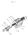
- the support device comprises a correspondingly shaped case 10, which is normally made of plastic material, and inside which there is mounted a metal pin 11 that is biased, ie. loaded by a compression spring 12, equally of metal.
- the case 10 is inserted in the thickness of a shelf 13 ( Figures 2, 3 and 4) with the front surface thereof lying flush with the border of the same shelf.
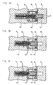
- the pin 11 is adapted to take three different operating positions, in which the first one ( Figures 2A and 3A) corresponds to the pin 11 being inserted in a receptacle 14 provided in a wall 15 of the cabinet, the second one ( Figures 2B and 3B) corresponds to a transitory condition of said pin 11 being released, ie. disengaged from the receptacle 14 in said wall 15, and the third one ( Figures 2C and 3C) corresponds to the condition in which the pin 11 is kept in a stable manner inside the case 10.
- the case 10 ( Figures 1 and 4) has a body featuring a front portion having a cross-sectional size that is greater than the corresponding size of the rear portion thereof.
- the front portion is formed to include a flat base-plate 16 provided with a longitudinal slot 17 and a plurality of longitudinal ribs 18, to the purpose of enabling the same case 10 to be firmly secured in a stable position inside the shelf 13.
- the base-plate 16 is further provided with a longitudinal bevel 19 (see in particular Figure 4), which is provided in a position that is diametrically opposed to the one of the base-plate or flat portion 16, in view of creating a strain-relief aimed at reducing the pressure exerted onto the shelf 13 when the latter is loaded.
- the case 10 is provided with a substantially constant-diameter bore extending longitudinally therethrough.
- the pin 11 is bored axially so as to be able to accommodate and guide the front end portion of the spring 12 ( Figures 2 and 3), which therefore is actually housed between the inner extremity of the case 10 and the corresponding extremity of the bore of the pin 11.
- the pin 11 is further provided with a concave tooth 20 and must be mounted inside the case 10 in such a manner as to enable this tooth 20 to lie facing the slot 17.
- the purpose of such a tooth 20 is in fact to enable the pin 11 to be operated with the aid of an appropriate tool (eg. a screwdriver), so as to cause it to slide within the case 10, when a need arises for the shelf 13 to be released from the wall 15.
- the pin 11 is provided with a couple of pairs of mutually opposing relieves 21, 22 ( Figures 3A-3C) that are adapted to cooperate with two diametrically opposed elastic tangs 23 extending inwards in an axial direction from the front edge of the case 10.
- the pin 11 is loaded, ie. biased by the spring 12 to extend out of the case 10 ( Figures 2A and 3A) in a locked position defined by the tangs 23 engaging, ie. abutting against the relieves 22.
- Such an abutment constitutes a positive and reliable stop contrivance in view of limiting the extent to which the pin is capable of sliding out of the case.
- the relieves 22 have such a right-angled sectional profile as to prove effective in providing a retaining means for the pin 11 to be retained against the tangs 23.
- the relieves 21 protrude from the body of the pin 11 to a lesser extent than the relieves 22 and have a sectional profile showing a plane with a reduced inclination so as to constitute an unstable abuttal for the free ends of the tangs 23.
- the aim of the present invention is therefore reached through the use of a pin 11 and a spring 12, both of them made of metal, which enable the respective diameters to be reduced, while however increasing their strength.
- the simplification in the shape of the pin 11 and the modification of the retaining system thereof allow for the overall size of the whole device to be reduced along with the mating or coupling allowances.
- the compactness of the case 10 makes the device adaptable also to shelves having a reduced thickness (eg. 16 mm), while anyway complying with the requirements of the applicable standard regulations.
Landscapes
- Assembled Shelves (AREA)
- Furniture Connections (AREA)
- Cabinets, Racks, Or The Like Of Rigid Construction (AREA)
- Supports Or Holders For Household Use (AREA)
- Display Racks (AREA)
- Casings For Electric Apparatus (AREA)
Claims (5)
- Dispositif de support destiné à être appliqué sur la bordure latérale d'une étagère, afin de permettre de positionner cette dernière dans les parois d'un meuble, tel qu'une armoire ou similaire, et de l'y fixer, d'une manière rapide et automatique, comprenant un étui (10) qui est inséré dans la bordure de l'étagère (13) et contient une broche élastique (11, 12) qui fait normalement saillie de la bordure de l'étagère et qui est adaptée pour glisser à nouveau dans ledit étui lorsque l'étagère est amenée en interférence avec la surface d'une paroi (15) de l'armoire, caractérisé en ce que la broche (11) comprend deux paires de détentes (21, 22) qui sont adaptées pour coopérer avec des tenons élastiques (23) s'étendant à l'intérieur de l'étui (10), dans lequel une première paire de détentes (21) constitue un engagement instable pour les extrémités libres des tenons (23), tandis que la seconde paire de détentes (22) constitue une butée pour limiter l'extension dans laquelle la broche (11) peut s'étendre hors de l'étui (10).
- Dispositif de support selon la revendication 1, caractérisé en ce que ladite seconde paire de détentes (22) présente un profil en coupe à angle droit, tandis que ladite première paire de détentes (21) fait moins saillie du corps de la broche (11) que les détentes (22) et présente un profil en coupe longitudinale montrant un plan à inclinaison réduite.
- Dispositif de support selon la revendication 1 ou 2, caractérisé en ce que la broche (11) comprend une dent concave (20) adaptée pour être actionnée, à travers une fente (17) prévue dans le corps de l'étui (10), au moyen d'un outil, afin de faire rétracter cette même broche à l'intérieur de l'étui et de permettre ainsi de retirer l'étagère (13) de la paroi (14) de l'armoire.
- Dispositif de support selon la revendication 3, caractérisé en ce que la fente (17) est prévue dans une plaque de base plate (16) de l'étui (10) constituant un élément de support pour l'ensemble du dispositif.
- Dispositif de support selon l'une quelconque des revendications précédentes, caractérisé en ce que la broche (11) est perforée dans le sens axial et le ressort (12) est logé entre l'extrémité intérieure de l'étui (10) et l'extrémité intérieure dudit alésage axial de la broche (11).
Applications Claiming Priority (2)
| Application Number | Priority Date | Filing Date | Title |
|---|---|---|---|
| ITPN010004U | 2001-02-05 | ||
| IT2001PN000004U ITPN20010004U1 (it) | 2001-02-05 | 2001-02-05 | Supporto per ripiani ad inserimento rapido per mobili e simili |
Publications (2)
| Publication Number | Publication Date |
|---|---|
| EP1228721A1 EP1228721A1 (fr) | 2002-08-07 |
| EP1228721B1 true EP1228721B1 (fr) | 2004-04-07 |
Family
ID=11453209
Family Applications (1)
| Application Number | Title | Priority Date | Filing Date |
|---|---|---|---|
| EP02000992A Expired - Lifetime EP1228721B1 (fr) | 2001-02-05 | 2002-01-17 | Support d'étagère pour montage rapide, pour meubles et objets similaires |
Country Status (5)
| Country | Link |
|---|---|
| EP (1) | EP1228721B1 (fr) |
| AT (1) | ATE263503T1 (fr) |
| DE (1) | DE60200329T2 (fr) |
| ES (1) | ES2219584T3 (fr) |
| IT (1) | ITPN20010004U1 (fr) |
Families Citing this family (13)
| Publication number | Priority date | Publication date | Assignee | Title |
|---|---|---|---|---|
| EP1454565A1 (fr) | 2003-02-12 | 2004-09-08 | Agostino Ferrari S.p.A. | Un dispositif rétractable pour un support d'étagère dans un meuble |
| EP2177129B1 (fr) | 2008-10-14 | 2011-05-18 | Ferramenta Livenza S.r.l. | Dispositif de fixation amélioré pour étagères de meubles |
| GB2494462B (en) * | 2011-09-12 | 2014-09-10 | Christopher Mark Wilkinson | Invisible support structure |
| ITPN20110085A1 (it) * | 2011-12-30 | 2013-07-01 | Livenza Ferramenta Srl | Reggi piano a scomparsa |
| ITAN20120057A1 (it) * | 2012-05-14 | 2013-11-15 | Euro Orvel Srl | Reggipiano con molla di montaggio automatico e relativo dispositivo di apertura rapida manuale |
| ITMI20130076A1 (it) | 2013-01-22 | 2014-07-23 | Agostino Ferrari Spa | Dispositivo reggipiano a scomparsa per supportare un ripiano di un mobile e ripiano di mobile comprendente tale dispositivo |
| IT201900005830A1 (it) * | 2019-04-16 | 2020-10-16 | Car S R L | Dispositivo per il sostegno di un pannello removibile rispetto ad una parete di un mobile e metodo per montare e smontare un pannello removibile trasversalmente ad una parete di un mobile |
| DE212020000339U1 (de) | 2019-07-31 | 2021-01-21 | Leonardo S.R.L. | Tragvorrichtung für Möbelfachböden |
| IT201900016343A1 (it) * | 2019-09-16 | 2021-03-16 | Leonardo Srl | Dispositivo di supporto perfezionato per ripiani di mobili |
| IT202000014326A1 (it) | 2020-06-16 | 2021-12-16 | Effegi Brevetti Srl | Dispositivo di supporto e di fissaggio di ripiani di mobili |
| IT202000026563A1 (it) * | 2020-11-06 | 2022-05-06 | Leonardo Srl | Reggiripiano magnetico per il collegamento amovibile di ripiani alle spalle di mobili |
| IT202200004823A1 (it) | 2022-03-14 | 2023-09-14 | Leonardo Srl | Dispositivo compatto di supporto e fissaggio per ripiani di mobili |
| IT202200004841A1 (it) | 2022-03-14 | 2023-09-14 | Leonardo Srl | Dispositivo rigido di supporto e fissaggio per ripiani di mobili |
Family Cites Families (5)
| Publication number | Priority date | Publication date | Assignee | Title |
|---|---|---|---|---|
| US2252570A (en) * | 1940-06-22 | 1941-08-12 | Modern Steel Equipment Company | Cabinet shelf supporting means |
| FR2040601A5 (fr) * | 1969-04-04 | 1971-01-22 | Dariosecq | |
| US3750238A (en) * | 1971-12-28 | 1973-08-07 | Arundale Mfg Inc | Plastic spring lock |
| FR2655527B1 (fr) * | 1989-12-13 | 1994-07-08 | Hubert Aumaitre | Element empilable de presentation. |
| IT251736Y1 (it) | 2000-05-09 | 2004-01-20 | Livenza Ferramenta Srl | Dispositivo di supporto per un ripiano ad inserimento rapido permobili e simili |
-
2001
- 2001-02-05 IT IT2001PN000004U patent/ITPN20010004U1/it unknown
-
2002
- 2002-01-17 DE DE60200329T patent/DE60200329T2/de not_active Expired - Fee Related
- 2002-01-17 ES ES02000992T patent/ES2219584T3/es not_active Expired - Lifetime
- 2002-01-17 AT AT02000992T patent/ATE263503T1/de not_active IP Right Cessation
- 2002-01-17 EP EP02000992A patent/EP1228721B1/fr not_active Expired - Lifetime
Also Published As
| Publication number | Publication date |
|---|---|
| EP1228721A1 (fr) | 2002-08-07 |
| DE60200329T2 (de) | 2005-05-04 |
| ATE263503T1 (de) | 2004-04-15 |
| ITPN20010004U1 (it) | 2002-08-05 |
| ES2219584T3 (es) | 2004-12-01 |
| DE60200329D1 (de) | 2004-05-13 |
Similar Documents
| Publication | Publication Date | Title |
|---|---|---|
| EP1228721B1 (fr) | Support d'étagère pour montage rapide, pour meubles et objets similaires | |
| US6283311B1 (en) | Tool display rack | |
| US20080122333A1 (en) | Latch and release device of a slide assembly | |
| US6283348B1 (en) | Cellular telephone clip | |
| RU2738755C2 (ru) | Усовершенствованное приспособление для соединения деталей мебели и мебельных аксессуаров | |
| US5102079A (en) | Connecting assembly for a tripod | |
| US10123616B2 (en) | Tall cabinet quick release structure | |
| US5794902A (en) | Shelf bracket for use with a grooved shelf | |
| US20050218760A1 (en) | Drawer locking structure | |
| US12239226B2 (en) | Device for supporting and fixing shelves of furniture | |
| US5664792A (en) | Tool fixing mechanism | |
| CN116867400B (zh) | 用于将搁架支承和可移除地固定到家具的立柱的装置 | |
| WO2001003537A1 (fr) | Pince de serrage destinee au montage d'accessoires | |
| US20060051159A1 (en) | Positioning device for a foldable structure | |
| US20040232297A1 (en) | Shelf-supporting device with releasable jaw for shelf locking | |
| EP0451113A1 (fr) | Dispositif pour fixer un panneau à un tiroir de meuble | |
| KR101681752B1 (ko) | 선반고정장치 | |
| EP1530926A2 (fr) | Arrangement amélioré de support d'étagère | |
| JPH0324800B2 (fr) | ||
| US20030041741A1 (en) | Separable handle for cooking vessel and cooking vessel | |
| CN111713898B (zh) | 连接装置 | |
| KR102400759B1 (ko) | 슬라이딩 롤러 이탈 방지 장치 | |
| EP2151176A1 (fr) | Dispositif de fixation pour étagères de meubles | |
| KR940011054B1 (ko) | 휴대용 컴퓨터의 hdd 착탈구조와 그 방법 | |
| CN220109690U (zh) | 活动限位组件及清洁设备 |
Legal Events
| Date | Code | Title | Description |
|---|---|---|---|
| PUAI | Public reference made under article 153(3) epc to a published international application that has entered the european phase |
Free format text: ORIGINAL CODE: 0009012 |
|
| AK | Designated contracting states |
Kind code of ref document: A1 Designated state(s): AT BE CH CY DE DK ES FI FR GB GR IE IT LI LU MC NL PT SE TR |
|
| AX | Request for extension of the european patent |
Free format text: AL;LT;LV;MK;RO;SI |
|
| 17P | Request for examination filed |
Effective date: 20021008 |
|
| AKX | Designation fees paid |
Designated state(s): AT DE ES FR IT |
|
| GRAP | Despatch of communication of intention to grant a patent |
Free format text: ORIGINAL CODE: EPIDOSNIGR1 |
|
| GRAS | Grant fee paid |
Free format text: ORIGINAL CODE: EPIDOSNIGR3 |
|
| GRAA | (expected) grant |
Free format text: ORIGINAL CODE: 0009210 |
|
| AK | Designated contracting states |
Kind code of ref document: B1 Designated state(s): AT DE ES FR IT |
|
| REF | Corresponds to: |
Ref document number: 60200329 Country of ref document: DE Date of ref document: 20040513 Kind code of ref document: P |
|
| REG | Reference to a national code |
Ref country code: IE Ref legal event code: FG4D |
|
| REG | Reference to a national code |
Ref country code: ES Ref legal event code: FG2A Ref document number: 2219584 Country of ref document: ES Kind code of ref document: T3 |
|
| ET | Fr: translation filed | ||
| PLBE | No opposition filed within time limit |
Free format text: ORIGINAL CODE: 0009261 |
|
| STAA | Information on the status of an ep patent application or granted ep patent |
Free format text: STATUS: NO OPPOSITION FILED WITHIN TIME LIMIT |
|
| 26N | No opposition filed |
Effective date: 20050110 |
|
| PGFP | Annual fee paid to national office [announced via postgrant information from national office to epo] |
Ref country code: FR Payment date: 20051208 Year of fee payment: 5 |
|
| PGFP | Annual fee paid to national office [announced via postgrant information from national office to epo] |
Ref country code: AT Payment date: 20051209 Year of fee payment: 5 |
|
| PGFP | Annual fee paid to national office [announced via postgrant information from national office to epo] |
Ref country code: DE Payment date: 20051215 Year of fee payment: 5 |
|
| PGFP | Annual fee paid to national office [announced via postgrant information from national office to epo] |
Ref country code: ES Payment date: 20060113 Year of fee payment: 5 |
|
| PG25 | Lapsed in a contracting state [announced via postgrant information from national office to epo] |
Ref country code: DE Free format text: LAPSE BECAUSE OF NON-PAYMENT OF DUE FEES Effective date: 20070801 |
|
| REG | Reference to a national code |
Ref country code: FR Ref legal event code: ST Effective date: 20070930 |
|
| PG25 | Lapsed in a contracting state [announced via postgrant information from national office to epo] |
Ref country code: AT Free format text: LAPSE BECAUSE OF NON-PAYMENT OF DUE FEES Effective date: 20070117 |
|
| REG | Reference to a national code |
Ref country code: ES Ref legal event code: FD2A Effective date: 20070118 |
|
| PG25 | Lapsed in a contracting state [announced via postgrant information from national office to epo] |
Ref country code: FR Free format text: LAPSE BECAUSE OF NON-PAYMENT OF DUE FEES Effective date: 20070131 |
|
| PG25 | Lapsed in a contracting state [announced via postgrant information from national office to epo] |
Ref country code: ES Free format text: LAPSE BECAUSE OF NON-PAYMENT OF DUE FEES Effective date: 20070118 |
|
| PGFP | Annual fee paid to national office [announced via postgrant information from national office to epo] |
Ref country code: IT Payment date: 20210121 Year of fee payment: 20 |