EP1228854A2 - Dispositif pour l'application de la bande de roulement à la carcasse d'un pneu - Google Patents
Dispositif pour l'application de la bande de roulement à la carcasse d'un pneu Download PDFInfo
- Publication number
- EP1228854A2 EP1228854A2 EP02001011A EP02001011A EP1228854A2 EP 1228854 A2 EP1228854 A2 EP 1228854A2 EP 02001011 A EP02001011 A EP 02001011A EP 02001011 A EP02001011 A EP 02001011A EP 1228854 A2 EP1228854 A2 EP 1228854A2
- Authority
- EP
- European Patent Office
- Prior art keywords
- carcass
- tread
- support track
- support
- feed
- Prior art date
- Legal status (The legal status is an assumption and is not a legal conclusion. Google has not performed a legal analysis and makes no representation as to the accuracy of the status listed.)
- Granted
Links
- 238000005520 cutting process Methods 0.000 claims abstract description 11
- 238000013459 approach Methods 0.000 claims abstract description 3
- 238000002360 preparation method Methods 0.000 claims description 3
- 230000002349 favourable effect Effects 0.000 description 3
- 238000010276 construction Methods 0.000 description 2
- 230000003247 decreasing effect Effects 0.000 description 2
- 238000004519 manufacturing process Methods 0.000 description 2
- 238000003860 storage Methods 0.000 description 2
- 230000006978 adaptation Effects 0.000 description 1
- 238000005452 bending Methods 0.000 description 1
- 230000000295 complement effect Effects 0.000 description 1
- 238000011161 development Methods 0.000 description 1
- 230000018109 developmental process Effects 0.000 description 1
- 238000006073 displacement reaction Methods 0.000 description 1
- 230000000694 effects Effects 0.000 description 1
- 238000005516 engineering process Methods 0.000 description 1
- 238000001125 extrusion Methods 0.000 description 1
- 238000012805 post-processing Methods 0.000 description 1
- 238000012545 processing Methods 0.000 description 1
Images

Classifications
-
- B—PERFORMING OPERATIONS; TRANSPORTING
- B29—WORKING OF PLASTICS; WORKING OF SUBSTANCES IN A PLASTIC STATE IN GENERAL
- B29D—PRODUCING PARTICULAR ARTICLES FROM PLASTICS OR FROM SUBSTANCES IN A PLASTIC STATE
- B29D30/00—Producing pneumatic or solid tyres or parts thereof
- B29D30/06—Pneumatic tyres or parts thereof (e.g. produced by casting, moulding, compression moulding, injection moulding, centrifugal casting)
- B29D30/52—Unvulcanised treads, e.g. on used tyres; Retreading
- B29D30/54—Retreading
-
- B—PERFORMING OPERATIONS; TRANSPORTING
- B29—WORKING OF PLASTICS; WORKING OF SUBSTANCES IN A PLASTIC STATE IN GENERAL
- B29D—PRODUCING PARTICULAR ARTICLES FROM PLASTICS OR FROM SUBSTANCES IN A PLASTIC STATE
- B29D30/00—Producing pneumatic or solid tyres or parts thereof
- B29D30/06—Pneumatic tyres or parts thereof (e.g. produced by casting, moulding, compression moulding, injection moulding, centrifugal casting)
- B29D30/52—Unvulcanised treads, e.g. on used tyres; Retreading
- B29D30/58—Applying bands of rubber treads, i.e. applying camel backs
Definitions
- the invention relates to a document device, according to the Preamble of claim 1.
- the tread has already been proposed to the bottom of the carcass. After only a few Centimeters between the bottom of the carcass and the tread remain there, the application there is ergonomic extremely unfavorable, especially with large carcasses. Further the operation of the cutting device is practically only possible if the operator bends down. In addition, at this solution, however, the extruder translatory to the carcass be slidably mounted, which on the one hand Construction makes more complex and secondly a corresponding one reduced precision when feeding the binding rubber causes.
- German patent application P 100 38 471.4 the present applicant has proposed the tread to stretch.
- this solution requires a rigid attachment ahead of the feed path.
- the length of the tread to measure and based on a length measuring device on empirical values, based on which a table for different tread lengths with different Carcass diameters are set, the cutting device to operate.
- the invention is based on the object Document device according to the preamble of claim 1 create that improved delivery precision of the tread, while the Post-processing of the joint should be simplified.
- the solution according to the invention surprisingly offers an increased Precision in the manufacture of an applied to the carcass Tread.
- the tread just fed in contrast to the curved feeds according to the state of the art.
- the tread became the bend of the tread for feeding apparently long, even if he is straight again directed or in the opposite direction according to the curvature the carcass is bent.
- the Tables that are intended to compensate for the elongation are omitted.
- no consideration is given to the duration of the Feeding important because the restoring effect of the used Masses that the elongation compensated for after a certain time, is omitted according to the invention after no elongation during the tread feed is provided.
- the support track for the tread in its entirety while maintaining the straight Extension of the tread pivoted into a feed position and proceed.
- this requires a pivoting movement around a joint and on the other hand a translational one Movement of the support track, each in any suitable manner can be realized.
- It is preferably provided a Joint clearly spaced from the carcass, i.e. almost at provide opposite end of the support track.
- the required swivel angle is small.
- the translational, essentially horizontal movement of the Support track can be provided on a suitable guide rail his.
- Such a guide rail can be compared Realize inexpensively, especially since the storage forces are limited and in particular significantly less than that Extrusion forces from the bearing device for the Carcass, the carcass holder, must be included.
- the feed position that is to say the Carcass surface tangential position of the tread, can be set as desired, either manually or via an automatic control.
- the cutting device is also in the invention Solution always prefers approximately at working height such as the range 1 m to 1.20 m. This ensures that the operator can make the cut precisely.
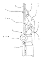
- the document device 10 shown in FIG. 1 has one Tread feeder 12 on which a not shown tread of a peeled carcass 14 can be supplied.
- the carcass 14 is on a carcass holder 16 rotatably mounted.
- the tread feed device 12 has one on one not visible guide rail guided support track 20.
- the support track 20 is towards the carcass 14 and away from it slidable and has on its top in itself known manner roles, not shown, on which the Tread can be moved with little friction.
- the Support track 20 a cutting device 22, which is shown in FIG is shown schematically and with the tread the desired length can be cut.
- the support track 20 is together with its guide rail pivoted.
- a joint 24 is provided a pivoting relative to a frame 26 of the document device 10 allows.
- a working cylinder 30 is used, which is on a support leg 32 acts, which is part of the guide rail.
- the support track 20 has a not shown Horizontal drive on, over which they compared Support leg 32 and also opposite the joint 24 in is essentially horizontally movable. So that is both Pivotal position as well as the horizontal position of the support track 20 adjustable at will.
- the support track 20 is in the preparation position.
- the treadmill can be pre-processed, for example via the cutting device 22 can be cut to the desired length.
- the Adjust the support track 20 to a feed position To do this First the end 28 to the carcass via the horizontal drive 14 go there. At the end 28 a sensor is attached, the the approach to the carcass surface is recorded. After the Carcass holder in the position shown in Fig. 1 is not the carcass diameter results from this. Then the Support track 20 raised and brought into the feed position. For this purpose, both the pivoting about the joint 24 and the Horizontal displacement based on the carcass diameter set so that exactly the desired feed position results in the tread tangential to the carcass surface extends.
- FIGS. 2 and 3 shows a carcass with a smaller diameter 3 shows a carcass with a larger diameter shows.
Landscapes
- Engineering & Computer Science (AREA)
- Mechanical Engineering (AREA)
- Tyre Moulding (AREA)
Applications Claiming Priority (2)
| Application Number | Priority Date | Filing Date | Title |
|---|---|---|---|
| DE10104774A DE10104774A1 (de) | 2001-02-02 | 2001-02-02 | Belegevorrichtung |
| DE10104774 | 2001-02-02 |
Publications (3)
| Publication Number | Publication Date |
|---|---|
| EP1228854A2 true EP1228854A2 (fr) | 2002-08-07 |
| EP1228854A3 EP1228854A3 (fr) | 2003-04-23 |
| EP1228854B1 EP1228854B1 (fr) | 2006-03-15 |
Family
ID=7672666
Family Applications (1)
| Application Number | Title | Priority Date | Filing Date |
|---|---|---|---|
| EP02001011A Expired - Lifetime EP1228854B1 (fr) | 2001-02-02 | 2002-01-17 | Dispositif pour l'application de la bande de roulement à la carcasse d'un pneu |
Country Status (4)
| Country | Link |
|---|---|
| US (1) | US20020139468A1 (fr) |
| EP (1) | EP1228854B1 (fr) |
| DE (1) | DE10104774A1 (fr) |
| DK (1) | DK1228854T3 (fr) |
Cited By (2)
| Publication number | Priority date | Publication date | Assignee | Title |
|---|---|---|---|---|
| EP1935627A1 (fr) * | 2006-12-21 | 2008-06-25 | The Goodyear Tire & Rubber Company | Applicateur d'ensemble pneu doté d'un mécanisme de découpage |
| EP1935626A1 (fr) * | 2006-12-21 | 2008-06-25 | The Goodyear Tire & Rubber Company | Applicateur d'ensemble pneu doté d'un mécanisme de découpage |
Citations (1)
| Publication number | Priority date | Publication date | Assignee | Title |
|---|---|---|---|---|
| DE10038471A1 (de) | 2000-08-07 | 2002-02-28 | Az Formen & Maschbau Gmbh | Verfahren zum Herstellen oder Runderneuern eines Reifens sowie Laufstreifen-Auftragvorrichtung |
Family Cites Families (6)
| Publication number | Priority date | Publication date | Assignee | Title |
|---|---|---|---|---|
| DE2318743B2 (de) * | 1973-04-13 | 1975-06-12 | Continental Gummi-Werke Ag, 3000 Hannover | Vorrichtung zum Berichtigen der Länge vulkanisierbarer Rohlaufstreifen |
| US4769104A (en) * | 1986-11-11 | 1988-09-06 | Bridgestone Corporation | Apparatus for sticking a tire component member |
| US5092946A (en) * | 1989-02-22 | 1992-03-03 | Bridgestone Corporation | Method for sticking a belt-like member and apparatus therefore |
| IT1240368B (it) * | 1990-04-27 | 1993-12-10 | Firestone International Developments.P.A. | Metodo e dispostitivo per l'alimentazione diretta a caldo di tratti di un battistrada estruso ad una macchina di formatura di pneumatici di autoveicoli |
| US5248374A (en) * | 1990-08-08 | 1993-09-28 | Toyo Tire & Rubber Co., Ltd. | Strip winder for a tire building machine |
| JP3439877B2 (ja) * | 1995-04-28 | 2003-08-25 | 横浜ゴム株式会社 | ベルト材料供給方法及び装置 |
-
2001
- 2001-02-02 DE DE10104774A patent/DE10104774A1/de not_active Withdrawn
-
2002
- 2002-01-17 EP EP02001011A patent/EP1228854B1/fr not_active Expired - Lifetime
- 2002-01-17 DK DK02001011T patent/DK1228854T3/da active
- 2002-02-01 US US10/066,282 patent/US20020139468A1/en not_active Abandoned
Patent Citations (1)
| Publication number | Priority date | Publication date | Assignee | Title |
|---|---|---|---|---|
| DE10038471A1 (de) | 2000-08-07 | 2002-02-28 | Az Formen & Maschbau Gmbh | Verfahren zum Herstellen oder Runderneuern eines Reifens sowie Laufstreifen-Auftragvorrichtung |
Cited By (3)
| Publication number | Priority date | Publication date | Assignee | Title |
|---|---|---|---|---|
| EP1935627A1 (fr) * | 2006-12-21 | 2008-06-25 | The Goodyear Tire & Rubber Company | Applicateur d'ensemble pneu doté d'un mécanisme de découpage |
| EP1935626A1 (fr) * | 2006-12-21 | 2008-06-25 | The Goodyear Tire & Rubber Company | Applicateur d'ensemble pneu doté d'un mécanisme de découpage |
| JP2008155642A (ja) * | 2006-12-21 | 2008-07-10 | Goodyear Tire & Rubber Co:The | 切断機構を有するタイヤ組立体貼り付け装置 |
Also Published As
| Publication number | Publication date |
|---|---|
| EP1228854B1 (fr) | 2006-03-15 |
| EP1228854A3 (fr) | 2003-04-23 |
| US20020139468A1 (en) | 2002-10-03 |
| DE10104774A1 (de) | 2002-08-08 |
| DK1228854T3 (da) | 2006-07-10 |
Similar Documents
| Publication | Publication Date | Title |
|---|---|---|
| DE19983582B4 (de) | Verfahren für eine Entastungsvorrichtung und Entastungsvorrichtung | |
| DE69526455T2 (de) | Vorrichtung zur Herstellung von Blättern aus Material mit gleichmässiger Dicke und zum Schneiden einzelner Teile daraus | |
| DE102011000205A1 (de) | Vorrichtung und Verfahren zum Reffen eines Schlauchfolienabschnitts | |
| DE1752211C3 (de) | Feinblechrichtmaschine | |
| WO1991006382A1 (fr) | Dispositif pour le pliage d'une tole | |
| DE2246693A1 (de) | Verfahren und vorrichtung zum verjuengtwalzen von metall | |
| EP0964756B1 (fr) | Dispositif pour redresser des lames de scie allongees, notamment pour scies a ruban | |
| EP1704971B1 (fr) | Méthode et dispositif de coupe pour produits alimentaires ayant une forme allongée | |
| DE3535760A1 (de) | Schweissgeraet | |
| EP1228854A2 (fr) | Dispositif pour l'application de la bande de roulement à la carcasse d'un pneu | |
| DE3812685C2 (de) | Verzögerungs-Vorrichtung für Bogenlagen | |
| DE3243257C1 (de) | Vorrichtung zum Abstuetzen des abzuschneidenden Streifens an einer Schere zum Schneiden von Blechen u.dgl. | |
| DE4240933C2 (de) | Vorrichtung zur Herstellung von Passepartouts für Bilder oder Schriftstücke | |
| DE102007063081A1 (de) | Belageinrichtung einer Maschine der Tabak verarbeitenden Industrie | |
| EP1726209A2 (fr) | Système d'enroulement pour des pièces de pâte et de matériau de remplissage | |
| DE3220489A1 (de) | Siebdruckmaschine | |
| DE4232276C2 (de) | Vorrichtung zum Abgeben und Zuführen von Stahl-Gummi-Halbfabrikaten zu einer Reifenaufbautrommel | |
| DE3422352A1 (de) | Vorrichtung zum aufschichten eines angenaehert flachbreiten stranges zu einem etwa quaderfoermigen block | |
| DE1965299A1 (de) | Vorrichtung zum Aufwickeln von band- oder bahnfoermigem Material im Kontaktwalzen-Verfahren | |
| DE2806973A1 (de) | Vorrichtung zum aufbringen von strangabschnitten auf einen rotationskoerper | |
| AT397364B (de) | Gerät zum schneiden von isolationsmaterial | |
| DE576788C (de) | Vorrichtung zum Schlingen von Brezeln | |
| EP0143452A2 (fr) | Dispositif pour couper et enrouler des rubans en métal ou des bandes en métal | |
| DE3830458A1 (de) | Vorrichtung zum verlegen von bahnen, insbesondere von textilmatten, auf der sohle und der boeschung eines gewaessers | |
| DE102005013733A1 (de) | Verfahren und Vorrichtung zum Schneiden von strangförmigen Lebensmitteln |
Legal Events
| Date | Code | Title | Description |
|---|---|---|---|
| PUAI | Public reference made under article 153(3) epc to a published international application that has entered the european phase |
Free format text: ORIGINAL CODE: 0009012 |
|
| AK | Designated contracting states |
Kind code of ref document: A2 Designated state(s): AT BE CH CY DE DK ES FI FR GB GR IE IT LI LU MC NL PT SE TR |
|
| AX | Request for extension of the european patent |
Free format text: AL;LT;LV;MK;RO;SI |
|
| PUAL | Search report despatched |
Free format text: ORIGINAL CODE: 0009013 |
|
| AK | Designated contracting states |
Designated state(s): AT BE CH CY DE DK ES FI FR GB GR IE IT LI LU MC NL PT SE TR |
|
| AX | Request for extension of the european patent |
Extension state: AL LT LV MK RO SI |
|
| 17P | Request for examination filed |
Effective date: 20031022 |
|
| 17Q | First examination report despatched |
Effective date: 20031113 |
|
| AKX | Designation fees paid |
Designated state(s): DK IT |
|
| REG | Reference to a national code |
Ref country code: DE Ref legal event code: 8566 |
|
| GRAP | Despatch of communication of intention to grant a patent |
Free format text: ORIGINAL CODE: EPIDOSNIGR1 |
|
| GRAS | Grant fee paid |
Free format text: ORIGINAL CODE: EPIDOSNIGR3 |
|
| GRAA | (expected) grant |
Free format text: ORIGINAL CODE: 0009210 |
|
| RAP1 | Party data changed (applicant data changed or rights of an application transferred) |
Owner name: VMI - AZ EXTRUSION GMBH |
|
| AK | Designated contracting states |
Kind code of ref document: B1 Designated state(s): DK IT |
|
| PG25 | Lapsed in a contracting state [announced via postgrant information from national office to epo] |
Ref country code: IT Free format text: LAPSE BECAUSE OF FAILURE TO SUBMIT A TRANSLATION OF THE DESCRIPTION OR TO PAY THE FEE WITHIN THE PRE;WARNING: LAPSES OF ITALIAN PATENTS WITH EFFECTIVE DATE BEFORE 2007 MAY HAVE OCCURRED AT ANY TIME BEFORE 2007. THE CORRECT EFFECTIVE DATE MAY BE DIFFERENT FROM THE ONE RECORDED.SCRIBED TIME-LIMIT Effective date: 20060315 |
|
| REG | Reference to a national code |
Ref country code: DK Ref legal event code: T3 |
|
| PLBE | No opposition filed within time limit |
Free format text: ORIGINAL CODE: 0009261 |
|
| STAA | Information on the status of an ep patent application or granted ep patent |
Free format text: STATUS: NO OPPOSITION FILED WITHIN TIME LIMIT |
|
| PGFP | Annual fee paid to national office [announced via postgrant information from national office to epo] |
Ref country code: DK Payment date: 20070123 Year of fee payment: 6 |
|
| 26N | No opposition filed |
Effective date: 20061218 |
|
| REG | Reference to a national code |
Ref country code: DK Ref legal event code: EBP |
|
| PG25 | Lapsed in a contracting state [announced via postgrant information from national office to epo] |
Ref country code: DK Free format text: LAPSE BECAUSE OF NON-PAYMENT OF DUE FEES Effective date: 20080131 |