EP1229207B1 - Arrangement de profilés - Google Patents
Arrangement de profilés Download PDFInfo
- Publication number
- EP1229207B1 EP1229207B1 EP02000585A EP02000585A EP1229207B1 EP 1229207 B1 EP1229207 B1 EP 1229207B1 EP 02000585 A EP02000585 A EP 02000585A EP 02000585 A EP02000585 A EP 02000585A EP 1229207 B1 EP1229207 B1 EP 1229207B1
- Authority
- EP
- European Patent Office
- Prior art keywords
- profile
- guide element
- cable
- arrangement according
- opening
- Prior art date
- Legal status (The legal status is an assumption and is not a legal conclusion. Google has not performed a legal analysis and makes no representation as to the accuracy of the status listed.)
- Expired - Lifetime
Links
- 238000010276 construction Methods 0.000 claims description 4
- 235000014676 Phragmites communis Nutrition 0.000 claims description 3
- 239000000463 material Substances 0.000 abstract description 3
- 238000009434 installation Methods 0.000 abstract description 2
- 229910052782 aluminium Inorganic materials 0.000 description 2
- XAGFODPZIPBFFR-UHFFFAOYSA-N aluminium Chemical compound [Al] XAGFODPZIPBFFR-UHFFFAOYSA-N 0.000 description 2
- 150000001875 compounds Chemical class 0.000 description 2
- 230000007613 environmental effect Effects 0.000 description 2
- 239000011521 glass Substances 0.000 description 2
- 229910052751 metal Inorganic materials 0.000 description 2
- 239000002184 metal Substances 0.000 description 2
- 238000004382 potting Methods 0.000 description 2
- HCHKCACWOHOZIP-UHFFFAOYSA-N Zinc Chemical compound [Zn] HCHKCACWOHOZIP-UHFFFAOYSA-N 0.000 description 1
- 238000004512 die casting Methods 0.000 description 1
- 230000005611 electricity Effects 0.000 description 1
- 230000003014 reinforcing effect Effects 0.000 description 1
- 238000007789 sealing Methods 0.000 description 1
- 239000002023 wood Substances 0.000 description 1
- 229910052725 zinc Inorganic materials 0.000 description 1
- 239000011701 zinc Substances 0.000 description 1
Images
Classifications
-
- E—FIXED CONSTRUCTIONS
- E06—DOORS, WINDOWS, SHUTTERS, OR ROLLER BLINDS IN GENERAL; LADDERS
- E06B—FIXED OR MOVABLE CLOSURES FOR OPENINGS IN BUILDINGS, VEHICLES, FENCES OR LIKE ENCLOSURES IN GENERAL, e.g. DOORS, WINDOWS, BLINDS, GATES
- E06B3/00—Window sashes, door leaves, or like elements for closing wall or like openings; Layout of fixed or moving closures, e.g. windows in wall or like openings; Features of rigidly-mounted outer frames relating to the mounting of wing frames
- E06B3/04—Wing frames not characterised by the manner of movement
- E06B3/263—Frames with special provision for insulation
- E06B3/26301—Frames with special provision for insulation with prefabricated insulating strips between two metal section members
- E06B3/26303—Frames with special provision for insulation with prefabricated insulating strips between two metal section members with thin strips, e.g. defining a hollow space between the metal section members
-
- E—FIXED CONSTRUCTIONS
- E06—DOORS, WINDOWS, SHUTTERS, OR ROLLER BLINDS IN GENERAL; LADDERS
- E06B—FIXED OR MOVABLE CLOSURES FOR OPENINGS IN BUILDINGS, VEHICLES, FENCES OR LIKE ENCLOSURES IN GENERAL, e.g. DOORS, WINDOWS, BLINDS, GATES
- E06B7/00—Special arrangements or measures in connection with doors or windows
- E06B7/16—Sealing arrangements on wings or parts co-operating with the wings
- E06B7/22—Sealing arrangements on wings or parts co-operating with the wings by means of elastic edgings, e.g. elastic rubber tubes; by means of resilient edgings, e.g. felt or plush strips, resilient metal strips
- E06B7/23—Plastic, sponge rubber, or like strips or tubes
- E06B7/2305—Plastic, sponge rubber, or like strips or tubes with an integrally formed part for fixing the edging
-
- H—ELECTRICITY
- H02—GENERATION; CONVERSION OR DISTRIBUTION OF ELECTRIC POWER
- H02G—INSTALLATION OF ELECTRIC CABLES OR LINES, OR OF COMBINED OPTICAL AND ELECTRIC CABLES OR LINES
- H02G11/00—Arrangements of electric cables or lines between relatively-movable parts
-
- E—FIXED CONSTRUCTIONS
- E05—LOCKS; KEYS; WINDOW OR DOOR FITTINGS; SAFES
- E05F—DEVICES FOR MOVING WINGS INTO OPEN OR CLOSED POSITION; CHECKS FOR WINGS; WING FITTINGS NOT OTHERWISE PROVIDED FOR, CONCERNED WITH THE FUNCTIONING OF THE WING
- E05F15/00—Power-operated mechanisms for wings
- E05F15/60—Power-operated mechanisms for wings using electrical actuators
- E05F15/603—Power-operated mechanisms for wings using electrical actuators using rotary electromotors
- E05F15/611—Power-operated mechanisms for wings using electrical actuators using rotary electromotors for swinging wings
-
- E—FIXED CONSTRUCTIONS
- E05—LOCKS; KEYS; WINDOW OR DOOR FITTINGS; SAFES
- E05Y—INDEXING SCHEME ASSOCIATED WITH SUBCLASSES E05D AND E05F, RELATING TO CONSTRUCTION ELEMENTS, ELECTRIC CONTROL, POWER SUPPLY, POWER SIGNAL OR TRANSMISSION, USER INTERFACES, MOUNTING OR COUPLING, DETAILS, ACCESSORIES, AUXILIARY OPERATIONS NOT OTHERWISE PROVIDED FOR, APPLICATION THEREOF
- E05Y2900/00—Application of doors, windows, wings or fittings thereof
- E05Y2900/10—Application of doors, windows, wings or fittings thereof for buildings or parts thereof
- E05Y2900/13—Type of wing
- E05Y2900/148—Windows
-
- E—FIXED CONSTRUCTIONS
- E06—DOORS, WINDOWS, SHUTTERS, OR ROLLER BLINDS IN GENERAL; LADDERS
- E06B—FIXED OR MOVABLE CLOSURES FOR OPENINGS IN BUILDINGS, VEHICLES, FENCES OR LIKE ENCLOSURES IN GENERAL, e.g. DOORS, WINDOWS, BLINDS, GATES
- E06B3/00—Window sashes, door leaves, or like elements for closing wall or like openings; Layout of fixed or moving closures, e.g. windows in wall or like openings; Features of rigidly-mounted outer frames relating to the mounting of wing frames
- E06B3/04—Wing frames not characterised by the manner of movement
- E06B3/263—Frames with special provision for insulation
- E06B2003/26349—Details of insulating strips
- E06B2003/2635—Specific form characteristics
- E06B2003/26361—Openings, incisions or indents
-
- E—FIXED CONSTRUCTIONS
- E06—DOORS, WINDOWS, SHUTTERS, OR ROLLER BLINDS IN GENERAL; LADDERS
- E06B—FIXED OR MOVABLE CLOSURES FOR OPENINGS IN BUILDINGS, VEHICLES, FENCES OR LIKE ENCLOSURES IN GENERAL, e.g. DOORS, WINDOWS, BLINDS, GATES
- E06B3/00—Window sashes, door leaves, or like elements for closing wall or like openings; Layout of fixed or moving closures, e.g. windows in wall or like openings; Features of rigidly-mounted outer frames relating to the mounting of wing frames
- E06B3/04—Wing frames not characterised by the manner of movement
- E06B3/263—Frames with special provision for insulation
- E06B2003/26349—Details of insulating strips
- E06B2003/26387—Performing extra functions
- E06B2003/2639—Provisions for fittings, e.g. locks or hinges
-
- H—ELECTRICITY
- H02—GENERATION; CONVERSION OR DISTRIBUTION OF ELECTRIC POWER
- H02G—INSTALLATION OF ELECTRIC CABLES OR LINES, OR OF COMBINED OPTICAL AND ELECTRIC CABLES OR LINES
- H02G3/00—Installations of electric cables or lines or protective tubing therefor in or on buildings, equivalent structures or vehicles
- H02G3/02—Details
- H02G3/04—Protective tubing or conduits, e.g. cable ladders or cable troughs
- H02G3/0462—Tubings, i.e. having a closed section
- H02G3/0487—Tubings, i.e. having a closed section with a non-circular cross-section
-
- H—ELECTRICITY
- H02—GENERATION; CONVERSION OR DISTRIBUTION OF ELECTRIC POWER
- H02G—INSTALLATION OF ELECTRIC CABLES OR LINES, OR OF COMBINED OPTICAL AND ELECTRIC CABLES OR LINES
- H02G3/00—Installations of electric cables or lines or protective tubing therefor in or on buildings, equivalent structures or vehicles
- H02G3/22—Installations of cables or lines through walls, floors or ceilings, e.g. into buildings
Definitions
- the present invention relates to a profile arrangement, in particular for electrically operated windows, doors, facades, light roof constructions or the like, with a profile in which at least one cavity is formed, in which a cable is guided, which emerges from the profile at an opening.
- window and door elements in which electrical components are used, for example, to tilt windows or doors or turn. Furthermore, sensors are mounted to sense the respective position of the windows, doors or other elements. In addition, electrical components in the form of sensors, for example, used as a burglar alarm. In all constructions, the respective elements must be supplied with electricity and, consequently, wired.
- the cable routing often proves difficult and it is desirable to route the cables within a profile in a corresponding cavity.
- the cable then emerges from an aperture or sash frame at an opening to electrically energize an element.
- the cable routing is also difficult, because not all areas of a hollow profile can be used for cable management, as this corner connectors, anchors or other components is reserved.
- the main disadvantage comes into play, that for the electrical work usually a specialist is consulted, who does not know the profiles or the profile systems.
- another skilled person is used for the metal construction work, who has difficulties to carry out electrical work, since this person skilled in the art of the electrician is unfamiliar. Here, therefore, two businesses collide.
- the DE 31 05 311 discloses a flexible conduit for guiding a cable from a door frame to a door connected thereto.
- the FR 2 641 820 discloses a frame profile of a door frame, with a flexible cable channel for guiding a cable of an electric locking device, which leads from a door to the door frame.
- the cable can be guided in a protected manner from the profile arrangement to the electrical acceptance element.
- the cable guide can already be done during assembly of the profile, so that the Installation work can be performed by the metal workers, who can then supply the profile assembly already with the desired cables. Due to the guide element, the cable is pre-fixed and only needs to be connected. The deflection in the guide element also eliminates the need for additional processing on the profile, for example, no groove walls have to be milled off since the guide of the cable is taken over by the guide element.
- the guide element on a channel which surrounds the cable at least partially U-shaped.
- the cable is arranged protected by the guide element, in particular when the open area of the U-shaped channel is turned to the profile itself, so that the cable is captively received between the guide element and profile.
- the guide element has a pin with a recess for receiving the cable, which passes through the opening on the profile.
- the opening in the profile is usually still provided with sharp edges that have not been reworked. These edges can damage the cable. If the pin passes through the opening and in the pin, the cable is guided, a contact between the cable and the edges of the opening is avoided, so that there is no danger of damage.
- webs are formed on the guide element, which engage in grooves of the profile.
- projections may be formed on the webs, which are latched with an undercut groove on the profile.
- the channel extends from the opening in the profile approximately at right angles curved, wherein at one end-side web of the guide element, a passage opening is provided.
- the guide member has a bridge function to guide the cable from the opening to a further position on the profile. Since the purposes of the guide element may be different, it is advantageous if at least one further branch channel for receiving the cable in the guide element is provided, which extends substantially perpendicular to the channel. As a result, the cable can also be inserted into the branch channel if required.
- the guide element In order to simultaneously use the guide element as a sensor, a reed contact, a magnetic switch or other sensor can be integrated in the guide element.
- the guide element is partially filled with a potting compound to receive the sensor. This potting compound gives the housing stability and allows easy mounting of the sensor on the profile.
- the guide element is preferably made of plastic. Other materials, e.g. Zinc diecasting is possible.
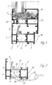
- FIG. 1 is a section through an aluminum hollow profile window shown.
- the window comprises a stationary frame 1 and a movable sash 2, in which a filling plate, for example an insulating glass pane 3 is inserted.
- a wall connection side 4 Adjacent to the frame 1, a wall connection side 4 is provided to secure the frame 1.
- Usually 4 cables are inserted into the hollow profile of the frame on the wall connection side.
- the frame 1 and the sash 2 is thermally insulated Aluminum profile executed. It is also possible to use other profiles, for example made of plastic or wood.
- the frame profile 1 comprises hollow chambers 5, 6 and 7, wherein the hollow chamber 6 is formed between two insulating webs 9. At the facing to the sash 2 insulating strip 9, a sealing profile 8 is arranged.
- the sash profile 2 has cavities 10, 11 and 12 wherein the central cavity 11 is formed between two insulating webs 13. Furthermore, a cavity 14 in the region of the glass rebate is formed on the casement profile 2. In these cavities 5, 6, 7, 10, 11, 12, and 14 cables and small electrical components can be mounted.
- a cable 15 is guided on the window frame profile 1, which runs with a portion 16 in the cavity 6 between the insulating webs 9. It is also possible to attach the guide member 20 at another location of the frame profile 1 to use another cavity for cable management.
- the guide element 20 engages with a pin 21 through an opening formed in the insulating web 9 and is latched to the insulating web 9.
- webs 22 and 23 are formed with a projection on the guide element, which engage in an undercut groove 18 on the frame profile 1. As a result, the guide element is latched both on the undercut groove 18 and at the opening in the insulating web 9.
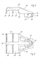
- the guide member 20 includes a channel 26 which engages an inserted cable 15 U-shaped, so that it is protected from environmental influences.
- the channel 26 extends from the insert 9 in the insulating pin 21 up to the end-side web 22, which is recessed a U-shaped passage opening.
- the deflection of a cable is indicated by the dashed line 27 in FIG FIG. 3 representing the top edge of the channel 26.
- a projection 24 is formed, so that between the projection 24 and a bottom portion 31 of the guide member 20, a recess 25 is provided.
- the thickness of the recess 25 corresponds approximately to the thickness of the insulating web 9, so that the guide element 20 is held on the insulating web 9 by means of the projection 24.
- FIG. 4 it can be seen forms a branch channel 28 between the webs 22 and 23. If the cable 15 is not to be sensed out of the frame profile 1, the cable 15 can be placed by the channel 26 in the branch channel 28 so as to continue the cable 15 in the undercut groove 18. Further, a branch channel 29 is formed between the web 23 and a wall 32 on the guide member 20, which is also used for cable management. In this embodiment, however, a wall of the undercut groove 18 is received in the branch channel 29. Furthermore, cavities 30 are recessed in the guide element 20.
- the guide member 20 is formed of plastic and can be used universally for different purposes.
- the guide element 20 can have latching receptacles for sensors.
- the guide member 20 may be equipped with reinforcing struts for mechanical loads.
- the cable 15 is protected from environmental influences. Furthermore, the cable 15 can be safely mounted already during assembly of the frame profile or later, wherein by means of the guide member 20, the positioning of the cable 15 can be carried out.
- a reed contact is inserted in the guide element 20, wherein it is held with a filling material in the guide element. It is also possible to insert magnetic switches or other sensors in the guide element.
- the guide element 20 may also be designed as a plug.
- openings may be formed on the guide element to provide a plug contact or a socket on the guide element. It can also be provided on the guide element several plug contacts or sockets, which are supplied via the cable or several cables.
Landscapes
- Engineering & Computer Science (AREA)
- Civil Engineering (AREA)
- Structural Engineering (AREA)
- Installation Of Indoor Wiring (AREA)
- Burglar Alarm Systems (AREA)
- Circuits Of Receivers In General (AREA)
- Crushing And Grinding (AREA)
- Undergarments, Swaddling Clothes, Handkerchiefs Or Underwear Materials (AREA)
- Details Of Indoor Wiring (AREA)
Claims (10)
- Arrangement de profilés, destiné en particulier à des fenêtres, portes, façades, constructions de toiture vitrée motorisées ou à des constructions similaires, pourvu d'un profilé (1, 2) dans lequel est formée au moins une cavité (5, 6, 7, 10, 11, 12, 14) dans laquelle est passé un câble (15) qui sort du profilé (1, 2) par une ouverture, un élément de guidage (20) au niveau de l'ouverture étant prévu pour dévier le câble (15), caractérisé en ce que l'élément de guidage (20) comporte un canal (26) qui enveloppe le câble (15) au moins dans un secteur en forme de U.
- Arrangement de profilés selon la revendication 1, caractérisé en ce que l'élément de guidage (20) est encliqueté avec le profilé (1).
- Arrangement de profilés selon l'une quelconque des revendications 1 ou 2, caractérisé en ce que l'élément de guidage (20) comporte un tourillon (21) qui est pourvu d'un évidement pour recevoir le câble (15) et qui pénètre dans l'ouverture sur le profilé (1).
- Arrangement de profilés selon l'une quelconque des revendications 1 à 3, caractérisé en ce que des nervures (22, 23), qui s'engagent dans des gorges (18) du profilé, sont formées sur l'élément de guidage (20).
- Arrangement de profilés selon la revendication 4, caractérisé en ce que les nervures (22, 23) comportent des parties en saillie qui peuvent être encliquetées avec une gorge contre-dépouillée (18) du profilé (1).
- Arrangement de profilés selon l'une quelconque des revendications 1 à 5, caractérisé en ce que le canal (26) présente à partir de l'ouverture dans le profilé (1) une forme courbée à peu près à angle droit et en ce qu'il est prévu une ouverture débouchante dans une nervure terminale (22) de l'élément de guidage (20).
- Arrangement de profilés selon l'une quelconque des revendications 1 à 6, caractérisé en ce qu'il est prévu au moins un autre canal de dérivation (28, 29) qui est destiné à recevoir le câble (15) dans l'élément de guidage (20) et qui s'étend pratiquement perpendiculairement au canal (26).
- Arrangement de profilés selon l'une quelconque des revendications 1 à 7, caractérisé en ce qu'un capteur, de préférence un contact à lames souples, est intégré dans l'élément de guidage (20).
- Arrangement de profilés selon l'une quelconque des revendications 1 à 8, caractérisé en ce que l'élément de guidage (20) est en matière synthétique.
- Arrangement de profilés selon l'une quelconque des revendications 1 à 9, caractérisé en ce que l'élément de guidage (20) est conçu en tant que connecteur.
Applications Claiming Priority (2)
| Application Number | Priority Date | Filing Date | Title |
|---|---|---|---|
| DE20100757U | 2001-01-15 | ||
| DE20100757U DE20100757U1 (de) | 2001-01-15 | 2001-01-15 | Profilanordnung |
Publications (3)
| Publication Number | Publication Date |
|---|---|
| EP1229207A2 EP1229207A2 (fr) | 2002-08-07 |
| EP1229207A3 EP1229207A3 (fr) | 2003-11-19 |
| EP1229207B1 true EP1229207B1 (fr) | 2010-10-13 |
Family
ID=7951689
Family Applications (1)
| Application Number | Title | Priority Date | Filing Date |
|---|---|---|---|
| EP02000585A Expired - Lifetime EP1229207B1 (fr) | 2001-01-15 | 2002-01-10 | Arrangement de profilés |
Country Status (3)
| Country | Link |
|---|---|
| EP (1) | EP1229207B1 (fr) |
| AT (1) | ATE484869T1 (fr) |
| DE (2) | DE20100757U1 (fr) |
Families Citing this family (6)
| Publication number | Priority date | Publication date | Assignee | Title |
|---|---|---|---|---|
| DE102005001627A1 (de) * | 2005-01-12 | 2006-07-20 | Dorma Gmbh + Co. Kg | Trennwand aus Glas |
| DE202005000579U1 (de) * | 2005-01-14 | 2006-06-01 | Schüco International KG. | Profil für ein Fenster, eine Tür oder ein Fassadenelement mit elektrischem Kabel und Stecker für das Kabel |
| EA010343B1 (ru) * | 2005-01-14 | 2008-08-29 | Шюко Интернациональ Кг | Профиль для окна, двери или фасадного элемента с электрическим кабелем |
| DE102005002302A1 (de) * | 2005-01-17 | 2006-07-27 | Thyssenkrupp Steel Ag | Profilelement und Verwendungen eines solchen Profilelements |
| CN105735840A (zh) * | 2016-04-18 | 2016-07-06 | 浙江瑞明节能科技股份有限公司 | 一种专门配套用于门窗的玻璃压线条结构 |
| IT202100016001A1 (it) * | 2021-06-18 | 2022-12-18 | Kompany S R L | Sistema di installazione per infissi con viti a scomparsa |
Family Cites Families (4)
| Publication number | Priority date | Publication date | Assignee | Title |
|---|---|---|---|---|
| US4278834A (en) * | 1978-12-06 | 1981-07-14 | Westinghouse Electric Corp. | Versatile, electrified space dividing wall panel system |
| FI60057C (fi) * | 1980-02-20 | 1981-11-10 | Waertsilae Oy Ab | Anordning vid doerr |
| FR2641820A1 (fr) * | 1989-01-18 | 1990-07-20 | Brogser Sa | Huisserie de securite anti-vandalisme |
| US5135413A (en) * | 1991-08-21 | 1992-08-04 | Pannizzo Peter P | Window outlet |
-
2001
- 2001-01-15 DE DE20100757U patent/DE20100757U1/de not_active Expired - Lifetime
-
2002
- 2002-01-10 DE DE50214705T patent/DE50214705D1/de not_active Expired - Lifetime
- 2002-01-10 AT AT02000585T patent/ATE484869T1/de not_active IP Right Cessation
- 2002-01-10 EP EP02000585A patent/EP1229207B1/fr not_active Expired - Lifetime
Also Published As
| Publication number | Publication date |
|---|---|
| EP1229207A2 (fr) | 2002-08-07 |
| DE20100757U1 (de) | 2001-03-15 |
| EP1229207A3 (fr) | 2003-11-19 |
| DE50214705D1 (de) | 2010-11-25 |
| ATE484869T1 (de) | 2010-10-15 |
Similar Documents
| Publication | Publication Date | Title |
|---|---|---|
| DE69112304T2 (de) | Gehäuse für elektrische Niederspannungsgeräte. | |
| CH663291A5 (de) | Stromschiene mit stromentnahmevorrichtung. | |
| EP1229207B1 (fr) | Arrangement de profilés | |
| EP1836753B1 (fr) | Profile de fenetre ou de façade et cable electrique destine a un profile pour une fenetre, une porte ou une façade | |
| EP1836748B1 (fr) | Profile pour fenetre, porte ou element de façade avec cable electrique | |
| EP0654575B1 (fr) | Rail de contact de sécurité avec une couche protective | |
| DE19630877C2 (de) | Gleitschiene | |
| EP0545115B1 (fr) | Boîtier de contrÔle pour composants électriques, électroniques et mécaniques | |
| DE202005000579U1 (de) | Profil für ein Fenster, eine Tür oder ein Fassadenelement mit elektrischem Kabel und Stecker für das Kabel | |
| DE2850779C2 (de) | Türzarge zur Führung von elektrischen Leitern | |
| EP0452756A2 (fr) | Dispositif d'ancrage pour vitrages ayant l'air optiquement sans cadre | |
| DE3245384A1 (de) | Elektrische stromschiene zur stromversorgung sowie dazugehoerige anschlussvorrichtung | |
| DE69302158T2 (de) | Profileinrichtung für die Verkabelung elektrischer Apparate, und geeignetes Skelett und Rinne um eine solche Einrichtung zu bauen | |
| DE29823870U1 (de) | Kasten-Gehäuse zur Aufnahme mindestens einer Elektronikplatine | |
| EP1830444A1 (fr) | Armoire électrique | |
| DE3832535C2 (fr) | ||
| DE102021107998A1 (de) | Dichtung mit wenigstens einem integrierten Leiter | |
| DE20100618U1 (de) | Rahmenprofil | |
| DE3911901A1 (de) | Explosionsgeschuetzte leuchte | |
| DE69931832T2 (de) | Deckel-Übergangsstück zwischen zwei benachbarten, in linearer Folge angeordneten Elementen zur Befestigung an einem Aufnahmeprofil | |
| EP1728934A2 (fr) | Profilé pour cadres de fenêtres, cloisons ou portes | |
| DE19511463C1 (de) | Tragrahmen für elektrische Geräte der elektrischen Übertragungstechnik, insbesondere für Sprechanlagen | |
| DE202005000609U1 (de) | Profil für ein Fenster, eine Tür oder ein Fassadenelement mit elektrischem Kabel und Stecker für das Kabel | |
| DE202005000608U1 (de) | Profil für ein Fenster, eine Tür oder ein Fassadenelement und Tür, Fenster oder Fassadenelement | |
| EP1263103A2 (fr) | Dispositif d'attache pour cable |
Legal Events
| Date | Code | Title | Description |
|---|---|---|---|
| PUAI | Public reference made under article 153(3) epc to a published international application that has entered the european phase |
Free format text: ORIGINAL CODE: 0009012 |
|
| AK | Designated contracting states |
Kind code of ref document: A2 Designated state(s): AT BE CH CY DE DK ES FI FR GB GR IE IT LI LU MC NL PT SE TR |
|
| AX | Request for extension of the european patent |
Free format text: AL;LT PAYMENT 20020111;LV PAYMENT 20020111;MK;RO;SI |
|
| PUAL | Search report despatched |
Free format text: ORIGINAL CODE: 0009013 |
|
| AK | Designated contracting states |
Kind code of ref document: A3 Designated state(s): AT BE CH CY DE DK ES FI FR GB GR IE IT LI LU MC NL PT SE TR |
|
| AX | Request for extension of the european patent |
Extension state: AL LT LV MK RO SI |
|
| RIC1 | Information provided on ipc code assigned before grant |
Ipc: 7E 05D 11/00 B Ipc: 7H 02G 3/22 A Ipc: 7E 06B 3/263 B |
|
| 17P | Request for examination filed |
Effective date: 20040309 |
|
| AKX | Designation fees paid |
Designated state(s): AT BE CH CY DE DK ES FI FR GB GR IE IT LI LU MC NL PT SE TR |
|
| AXX | Extension fees paid |
Extension state: LT Payment date: 20020111 Extension state: SI Payment date: 20040309 Extension state: LV Payment date: 20020111 |
|
| 17Q | First examination report despatched |
Effective date: 20100223 |
|
| GRAP | Despatch of communication of intention to grant a patent |
Free format text: ORIGINAL CODE: EPIDOSNIGR1 |
|
| GRAS | Grant fee paid |
Free format text: ORIGINAL CODE: EPIDOSNIGR3 |
|
| GRAA | (expected) grant |
Free format text: ORIGINAL CODE: 0009210 |
|
| AK | Designated contracting states |
Kind code of ref document: B1 Designated state(s): AT BE CH CY DE DK ES FI FR GB GR IE IT LI LU MC NL PT SE TR |
|
| AX | Request for extension of the european patent |
Extension state: LT LV SI |
|
| REG | Reference to a national code |
Ref country code: GB Ref legal event code: FG4D Free format text: NOT ENGLISH |
|
| REG | Reference to a national code |
Ref country code: CH Ref legal event code: EP |
|
| REG | Reference to a national code |
Ref country code: IE Ref legal event code: FG4D Free format text: LANGUAGE OF EP DOCUMENT: GERMAN |
|
| REF | Corresponds to: |
Ref document number: 50214705 Country of ref document: DE Date of ref document: 20101125 Kind code of ref document: P |
|
| REG | Reference to a national code |
Ref country code: NL Ref legal event code: VDEP Effective date: 20101013 |
|
| LTIE | Lt: invalidation of european patent or patent extension |
Effective date: 20101013 |
|
| REG | Reference to a national code |
Ref country code: IE Ref legal event code: FD4D |
|
| PG25 | Lapsed in a contracting state [announced via postgrant information from national office to epo] |
Ref country code: PT Free format text: LAPSE BECAUSE OF FAILURE TO SUBMIT A TRANSLATION OF THE DESCRIPTION OR TO PAY THE FEE WITHIN THE PRESCRIBED TIME-LIMIT Effective date: 20110214 Ref country code: NL Free format text: LAPSE BECAUSE OF FAILURE TO SUBMIT A TRANSLATION OF THE DESCRIPTION OR TO PAY THE FEE WITHIN THE PRESCRIBED TIME-LIMIT Effective date: 20101013 Ref country code: FI Free format text: LAPSE BECAUSE OF FAILURE TO SUBMIT A TRANSLATION OF THE DESCRIPTION OR TO PAY THE FEE WITHIN THE PRESCRIBED TIME-LIMIT Effective date: 20101013 Ref country code: SE Free format text: LAPSE BECAUSE OF FAILURE TO SUBMIT A TRANSLATION OF THE DESCRIPTION OR TO PAY THE FEE WITHIN THE PRESCRIBED TIME-LIMIT Effective date: 20101013 |
|
| PG25 | Lapsed in a contracting state [announced via postgrant information from national office to epo] |
Ref country code: GR Free format text: LAPSE BECAUSE OF FAILURE TO SUBMIT A TRANSLATION OF THE DESCRIPTION OR TO PAY THE FEE WITHIN THE PRESCRIBED TIME-LIMIT Effective date: 20110114 |
|
| PG25 | Lapsed in a contracting state [announced via postgrant information from national office to epo] |
Ref country code: ES Free format text: LAPSE BECAUSE OF FAILURE TO SUBMIT A TRANSLATION OF THE DESCRIPTION OR TO PAY THE FEE WITHIN THE PRESCRIBED TIME-LIMIT Effective date: 20110124 Ref country code: IE Free format text: LAPSE BECAUSE OF FAILURE TO SUBMIT A TRANSLATION OF THE DESCRIPTION OR TO PAY THE FEE WITHIN THE PRESCRIBED TIME-LIMIT Effective date: 20101013 |
|
| BERE | Be: lapsed |
Owner name: SCHUCO INTERNATIONAL K.G. Effective date: 20110131 |
|
| PLBE | No opposition filed within time limit |
Free format text: ORIGINAL CODE: 0009261 |
|
| STAA | Information on the status of an ep patent application or granted ep patent |
Free format text: STATUS: NO OPPOSITION FILED WITHIN TIME LIMIT |
|
| PG25 | Lapsed in a contracting state [announced via postgrant information from national office to epo] |
Ref country code: MC Free format text: LAPSE BECAUSE OF NON-PAYMENT OF DUE FEES Effective date: 20110131 Ref country code: DK Free format text: LAPSE BECAUSE OF FAILURE TO SUBMIT A TRANSLATION OF THE DESCRIPTION OR TO PAY THE FEE WITHIN THE PRESCRIBED TIME-LIMIT Effective date: 20101013 |
|
| REG | Reference to a national code |
Ref country code: CH Ref legal event code: PL |
|
| 26N | No opposition filed |
Effective date: 20110714 |
|
| PG25 | Lapsed in a contracting state [announced via postgrant information from national office to epo] |
Ref country code: LI Free format text: LAPSE BECAUSE OF NON-PAYMENT OF DUE FEES Effective date: 20110131 Ref country code: CH Free format text: LAPSE BECAUSE OF NON-PAYMENT OF DUE FEES Effective date: 20110131 |
|
| REG | Reference to a national code |
Ref country code: DE Ref legal event code: R097 Ref document number: 50214705 Country of ref document: DE Effective date: 20110714 |
|
| PG25 | Lapsed in a contracting state [announced via postgrant information from national office to epo] |
Ref country code: BE Free format text: LAPSE BECAUSE OF NON-PAYMENT OF DUE FEES Effective date: 20110131 |
|
| PG25 | Lapsed in a contracting state [announced via postgrant information from national office to epo] |
Ref country code: IT Free format text: LAPSE BECAUSE OF FAILURE TO SUBMIT A TRANSLATION OF THE DESCRIPTION OR TO PAY THE FEE WITHIN THE PRESCRIBED TIME-LIMIT Effective date: 20101013 |
|
| REG | Reference to a national code |
Ref country code: AT Ref legal event code: MM01 Ref document number: 484869 Country of ref document: AT Kind code of ref document: T Effective date: 20110110 |
|
| PGFP | Annual fee paid to national office [announced via postgrant information from national office to epo] |
Ref country code: FR Payment date: 20120201 Year of fee payment: 11 |
|
| PGFP | Annual fee paid to national office [announced via postgrant information from national office to epo] |
Ref country code: GB Payment date: 20120124 Year of fee payment: 11 |
|
| PG25 | Lapsed in a contracting state [announced via postgrant information from national office to epo] |
Ref country code: AT Free format text: LAPSE BECAUSE OF NON-PAYMENT OF DUE FEES Effective date: 20110110 |
|
| PG25 | Lapsed in a contracting state [announced via postgrant information from national office to epo] |
Ref country code: LU Free format text: LAPSE BECAUSE OF NON-PAYMENT OF DUE FEES Effective date: 20110110 Ref country code: CY Free format text: LAPSE BECAUSE OF FAILURE TO SUBMIT A TRANSLATION OF THE DESCRIPTION OR TO PAY THE FEE WITHIN THE PRESCRIBED TIME-LIMIT Effective date: 20101013 |
|
| GBPC | Gb: european patent ceased through non-payment of renewal fee |
Effective date: 20130110 |
|
| PG25 | Lapsed in a contracting state [announced via postgrant information from national office to epo] |
Ref country code: TR Free format text: LAPSE BECAUSE OF FAILURE TO SUBMIT A TRANSLATION OF THE DESCRIPTION OR TO PAY THE FEE WITHIN THE PRESCRIBED TIME-LIMIT Effective date: 20101013 |
|
| REG | Reference to a national code |
Ref country code: FR Ref legal event code: ST Effective date: 20130930 |
|
| PG25 | Lapsed in a contracting state [announced via postgrant information from national office to epo] |
Ref country code: FR Free format text: LAPSE BECAUSE OF NON-PAYMENT OF DUE FEES Effective date: 20130131 Ref country code: GB Free format text: LAPSE BECAUSE OF NON-PAYMENT OF DUE FEES Effective date: 20130110 |
|
| PGFP | Annual fee paid to national office [announced via postgrant information from national office to epo] |
Ref country code: DE Payment date: 20160129 Year of fee payment: 15 |
|
| REG | Reference to a national code |
Ref country code: DE Ref legal event code: R119 Ref document number: 50214705 Country of ref document: DE |
|
| PG25 | Lapsed in a contracting state [announced via postgrant information from national office to epo] |
Ref country code: DE Free format text: LAPSE BECAUSE OF NON-PAYMENT OF DUE FEES Effective date: 20170801 |