EP1229242A2 - Zündanordnung mit einer integrierten Entstörabschmierung - Google Patents
Zündanordnung mit einer integrierten Entstörabschmierung Download PDFInfo
- Publication number
- EP1229242A2 EP1229242A2 EP01205029A EP01205029A EP1229242A2 EP 1229242 A2 EP1229242 A2 EP 1229242A2 EP 01205029 A EP01205029 A EP 01205029A EP 01205029 A EP01205029 A EP 01205029A EP 1229242 A2 EP1229242 A2 EP 1229242A2
- Authority
- EP
- European Patent Office
- Prior art keywords
- winding
- suppression
- secondary winding
- ignition apparatus
- spool
- Prior art date
- Legal status (The legal status is an assumption and is not a legal conclusion. Google has not performed a legal analysis and makes no representation as to the accuracy of the status listed.)
- Withdrawn
Links
- 230000001629 suppression Effects 0.000 title claims abstract description 83
- 238000004804 winding Methods 0.000 claims abstract description 148
- OKTJSMMVPCPJKN-UHFFFAOYSA-N Carbon Chemical compound [C] OKTJSMMVPCPJKN-UHFFFAOYSA-N 0.000 claims abstract description 6
- 229910052799 carbon Inorganic materials 0.000 claims abstract description 6
- PXHVJJICTQNCMI-UHFFFAOYSA-N Nickel Chemical compound [Ni] PXHVJJICTQNCMI-UHFFFAOYSA-N 0.000 claims abstract description 5
- 239000000463 material Substances 0.000 claims description 19
- 239000002184 metal Substances 0.000 claims description 7
- 229910052751 metal Inorganic materials 0.000 claims description 7
- 239000004020 conductor Substances 0.000 claims description 5
- RYGMFSIKBFXOCR-UHFFFAOYSA-N Copper Chemical compound [Cu] RYGMFSIKBFXOCR-UHFFFAOYSA-N 0.000 claims description 2
- 239000011248 coating agent Substances 0.000 claims description 2
- 238000000576 coating method Methods 0.000 claims description 2
- 238000010304 firing Methods 0.000 claims description 2
- 238000004519 manufacturing process Methods 0.000 claims description 2
- 238000000034 method Methods 0.000 claims 1
- 238000004382 potting Methods 0.000 description 12
- 239000004593 Epoxy Substances 0.000 description 7
- 238000010586 diagram Methods 0.000 description 7
- 238000013459 approach Methods 0.000 description 6
- 238000002485 combustion reaction Methods 0.000 description 6
- 239000008393 encapsulating agent Substances 0.000 description 6
- 239000011810 insulating material Substances 0.000 description 3
- 229920001707 polybutylene terephthalate Polymers 0.000 description 3
- 229920000728 polyester Polymers 0.000 description 3
- XEEYBQQBJWHFJM-UHFFFAOYSA-N Iron Chemical compound [Fe] XEEYBQQBJWHFJM-UHFFFAOYSA-N 0.000 description 2
- 230000000694 effects Effects 0.000 description 2
- 238000009413 insulation Methods 0.000 description 2
- 230000000750 progressive effect Effects 0.000 description 2
- 230000035882 stress Effects 0.000 description 2
- 229920001169 thermoplastic Polymers 0.000 description 2
- 239000004416 thermosoftening plastic Substances 0.000 description 2
- 229910000976 Electrical steel Inorganic materials 0.000 description 1
- 239000004727 Noryl Substances 0.000 description 1
- 229920001207 Noryl Polymers 0.000 description 1
- 239000004721 Polyphenylene oxide Substances 0.000 description 1
- 230000004323 axial length Effects 0.000 description 1
- 230000004888 barrier function Effects 0.000 description 1
- 230000015556 catabolic process Effects 0.000 description 1
- 230000006835 compression Effects 0.000 description 1
- 238000007906 compression Methods 0.000 description 1
- 238000010276 construction Methods 0.000 description 1
- 238000011217 control strategy Methods 0.000 description 1
- 230000008878 coupling Effects 0.000 description 1
- 238000010168 coupling process Methods 0.000 description 1
- 238000005859 coupling reaction Methods 0.000 description 1
- 238000007599 discharging Methods 0.000 description 1
- 238000010292 electrical insulation Methods 0.000 description 1
- 230000007613 environmental effect Effects 0.000 description 1
- 230000004907 flux Effects 0.000 description 1
- 230000006872 improvement Effects 0.000 description 1
- 238000009434 installation Methods 0.000 description 1
- 229910052742 iron Inorganic materials 0.000 description 1
- 238000002955 isolation Methods 0.000 description 1
- 230000033001 locomotion Effects 0.000 description 1
- 239000000696 magnetic material Substances 0.000 description 1
- 238000012986 modification Methods 0.000 description 1
- 230000004048 modification Effects 0.000 description 1
- 239000002245 particle Substances 0.000 description 1
- 230000035699 permeability Effects 0.000 description 1
- 239000004033 plastic Substances 0.000 description 1
- -1 polybutylene terephthalate Polymers 0.000 description 1
- 230000001681 protective effect Effects 0.000 description 1
- 230000004044 response Effects 0.000 description 1
- 230000000717 retained effect Effects 0.000 description 1
- 238000000926 separation method Methods 0.000 description 1
- 239000000758 substrate Substances 0.000 description 1
- 238000005382 thermal cycling Methods 0.000 description 1
- 230000008646 thermal stress Effects 0.000 description 1
Images


Classifications
-
- H—ELECTRICITY
- H04—ELECTRIC COMMUNICATION TECHNIQUE
- H04B—TRANSMISSION
- H04B15/00—Suppression or limitation of noise or interference
- H04B15/02—Reducing interference from electric apparatus by means located at or near the interfering apparatus
- H04B15/025—Reducing interference from ignition apparatus of fuel engines
-
- F—MECHANICAL ENGINEERING; LIGHTING; HEATING; WEAPONS; BLASTING
- F02—COMBUSTION ENGINES; HOT-GAS OR COMBUSTION-PRODUCT ENGINE PLANTS
- F02P—IGNITION, OTHER THAN COMPRESSION IGNITION, FOR INTERNAL-COMBUSTION ENGINES; TESTING OF IGNITION TIMING IN COMPRESSION-IGNITION ENGINES
- F02P13/00—Sparking plugs structurally combined with other parts of internal-combustion engines
-
- F—MECHANICAL ENGINEERING; LIGHTING; HEATING; WEAPONS; BLASTING
- F02—COMBUSTION ENGINES; HOT-GAS OR COMBUSTION-PRODUCT ENGINE PLANTS
- F02P—IGNITION, OTHER THAN COMPRESSION IGNITION, FOR INTERNAL-COMBUSTION ENGINES; TESTING OF IGNITION TIMING IN COMPRESSION-IGNITION ENGINES
- F02P3/00—Other installations
- F02P3/02—Other installations having inductive energy storage, e.g. arrangements of induction coils
-
- Y—GENERAL TAGGING OF NEW TECHNOLOGICAL DEVELOPMENTS; GENERAL TAGGING OF CROSS-SECTIONAL TECHNOLOGIES SPANNING OVER SEVERAL SECTIONS OF THE IPC; TECHNICAL SUBJECTS COVERED BY FORMER USPC CROSS-REFERENCE ART COLLECTIONS [XRACs] AND DIGESTS
- Y10—TECHNICAL SUBJECTS COVERED BY FORMER USPC
- Y10T—TECHNICAL SUBJECTS COVERED BY FORMER US CLASSIFICATION
- Y10T29/00—Metal working
- Y10T29/49—Method of mechanical manufacture
- Y10T29/49002—Electrical device making
- Y10T29/4902—Electromagnet, transformer or inductor
Definitions
- the present invention relates generally to ignition coils for developing a spark firing voltage that is applied to one or more spark plugs of an internal combustion engine.
- Ignition coils are known for use in connection with an internal combustion engine such as an automobile engine, and which include a primary winding, a secondary winding, and a magnetic circuit.
- the magnetic circuit conventionally may comprise a cylindrical-shaped, central core extending along an axis, located radially inwardly of the primary and secondary windings and magnetically coupled thereto.
- One end of the secondary winding is conventionally configured to produce a relatively high voltage when a primary current through the primary winding is interrupted.
- the high voltage end is coupled to a spark plug, as known, that is arranged to generate a discharge spark responsive to the high voltage.
- the spark plug operates as a noise generating source when such spark events occur, which may result in radio frequency interference (RFI).
- RFID radio frequency interference
- Separate mount ignition coils are generally connected to the spark plug through a spark plug cable, which has a minimizing effect on the RFI, due to its inherent inductance characteristics.
- Some types of ignition coils do not use ignition cables.
- a relatively slender ignition coil configuration is known that is adapted for mounting directly above a spark plug--commonly referred to as a "pencil” coil.
- Such ignition coils therefore, do not utilize ignition cables. Accordingly, the problem of RF noise presents particular challenges in the design of "pencil” (i.e., direct mount) coils.
- An object of the present invention is to solve one or more of the problems as set forth above.
- An ignition apparatus according to the present invention overcomes shortcomings of the conventional ignition apparatus by including a suppression device disposed outside of a magnetic circuit and comprising a suppression winding wound on the spool connected in series with the secondary winding.
- the foregoing approach eliminates thermal stresses associated with the conventional ignition coils that include a wire wound resistor.
- the present invention is less costly to implement compared to the use of the wire wound resistor.
- Being outside of the magnetic circuit allows the suppression device to present an inductance that is electrically distinct from the inductance associated with the secondary winding ⁇ this improves the suppression device's ability to reduce RF noise.
- An ignition apparatus comprises a magnetically permeable central core having a main axis, primary and secondary windings outwardly of the core.
- the secondary winding is wound on a secondary winding spool formed of magnetically non-permeable material.
- the core and the windings being included in a magnetic circuit.
- the apparatus further includes a suppression device disposed outside of the magnetic circuit comprising a suppression winding also wound on the spool and that is connected in series with the secondary winding.
- a method of making an ignition apparatus is also presented.
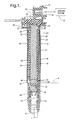
- FIG. 1 is a simplified, cross-section view of an ignition apparatus 10 in accordance with the present invention.
- ignition apparatus 10 may be coupled to, for example, an ignition system 12, which contains primary energization circuitry for controlling the charging and discharging of ignition apparatus 10.
- the relatively high voltage produced by ignition apparatus 10 is provided to a spark plug 14 (shown in phantom-line format) for producing a spark across a spark gap thereof, which may be employed to initiate combustion in a combustion chamber of an engine.
- Ignition system 12 and spark plug 14 perform conventional functions well known to those of ordinary skill in the art.
- Ignition apparatus 10 is adapted for installation to a conventional internal combustion engine through a spark plug well onto a high-voltage terminal of spark plug 14, which may be retained by a threaded engagement with a spark plug opening into the above-described combustion cylinder.
- the engine may provide power for locomotion of a vehicle, as known.
- Ignition apparatus 10 comprises a substantially slender high voltage transformer including substantially, coaxially arranged primary and secondary windings and a high permeability magnetic core.
- Figure 1 further shows a core 16, an optional first magnet 18, an optional second magnet 20, a primary winding 24, a first layer of encapsulant such as an epoxy potting material layer 26, a secondary winding spool 28, a secondary winding 30, a second epoxy potting material layer 32, a case 34, a shield 36, a low-voltage (LV) connector body 38, and a high-voltage (HV) connector assembly 40.
- spark plug 14 absent the improvement according to the present invention, constitutes a source of radio frequency noise or interference when producing sparks.
- FIG. 2 is a schematic representation of an ignition apparatus 10 according to the present invention.
- Ignition system 12 shown in block diagram form in Figure 1, includes a control unit 70 and a switch 72.
- Figure 2 further shows a suppression device 74 electrically connected in-series with secondary winding 30.
- ccontrol unit 70 is configured generally to perform a plurality of functions, including generation of an ignition control signal EST ( electronic spark timing).
- EST electronic spark timing
- the ignition control signal EST may be generated or initiated by other control units not shown, such as a powertrain control module (PCM) in accordance with known ignition control strategies, and provided to control unit 70, such that control unit 70 responds by driving switch 72 to closure in response thereto.
- PCM powertrain control module
- the ignition control signal defines the initial charging time (e.g., duration), and the relative timing (e.g., relative to cylinder top dead center) of when a spark is to occur.
- Switch 72 is configured to selectively connect primary winding 24 to ground, responsive to the ignition control signal. Such a connection to ground, as is known generally in the art, will cause a primary current I P to flow through primary winding 24.
- Switch 72 is illustrated in the Figures as a block diagram; however, it should be understood that switch 72 may comprise conventional components known to those of ordinary skill in the art, such as, for purposes of example only, an insulated gate bipolar transistor (IGBT).
- IGBT insulated gate bipolar transistor
- a voltage rise occurs across the secondary winding, a high voltage end of which is coupled to spark plug 14.
- the spaced electrodes of plug 14 (defining a gap therebetween) are shown in diagrammatic form in Figure 2.
- the induced voltage continues to rise across this gap until breakdown occurs, resulting in an electrical discharge across the gap (i.e., the spark).
- this discharge may lead to generation of radio frequency (RF) noise or interference.
- suppression device 74 is configured to suppress such RF noise.
- FIGS 3-6 illustrate various embodiments of suppression device 74, respectively designated suppression devices 74a, 74b, 74c and 74d. Each will be described in turn, with coordinated reference to Figure 7.
- FIG 3 shows suppression device 74a that includes a suppression winding 76 connected in series with secondary winding 30.
- Suppression winding 76 may comprise the same wire material used for the main turns of secondary winding 30 and may also be continuous therewith ( i.e., no breaks).
- FIG. 7 there is shown a perspective view of secondary winding spool 28 carrying a plurality of turns of wire on a main body portion thereof defining secondary winding 30.
- spool 28 may be formed with a channel 78 configured to allow axial routing of the wire that forms secondary winding 30.
- Figure 7 also shows a first terminal 80 and a second terminal 82, in addition to a high-voltage terminal 52 that connects to high-voltage connector assembly 40 (best shown in Figure 1).
- the main turns of secondary winding 30 are made, then, in a continuous fashion (e.g., on the same winder), further turns are made to form suppression winding 76. The end of the suppression winding 76 is then connected to high-voltage terminal 52.
- the diameter of the turns of suppression winding 76 is reduced relative to the diameter of the turns of secondary winding 30.
- the respective circular patterns of the secondary winding 30 and suppression winding 76 are substantially coaxial, although axially offset or spaced apart, one from another.
- the value of the inductance sought for suppression winding 76 will vary depending on the overall design of the ignition apparatus and the desired suppression bandwidth ranges.
- the secondary winding 30 may comprise between about 10,000-30,000 turns of 40-46 AWG polyester coated copper wire, and may more preferably be between about 15,000-25,000 turns, while the suppression winding 76 may comprise approximately 20 turns of the same wire at about a 16mm diameter ( e.g., which yields about 15 to 20 ⁇ H).
- suppression winding 76 (as well as winding 86 described below) is disposed outside of a magnetic circuit comprising core 16, windings 24 and 30, and shield 36. This is preferred since is presents the inductance provided by suppression winding 76 as distinct from the inductance provided by secondary winding 30, which improves the suppression effectiveness of suppression device 74.
- the lowermost axial extent of any of the components in the magnetic circuit is illustrated by the line designated "B", which corresponds to a lowermost axial edge or bottom of shield 36.
- shield 36, core 16 and magnets 18, 20 (if present) generally extend about the same axial length.
- Figures 4 and 5 show suppression devices 74b and 74c, respectively, each including a suppression winding 76 connected in series with a resistor 84.
- the embodiments of Figures 4 and 5 may be used when a resistance is desirable or required in order to obtain a predetermined suppression effect (i.e., to obtain a certain level of suppression over a certain bandwidth on or around a nominal center frequency).
- Resistor 84 may comprise a carbon resistor, which is much less expensive than wire wound resistor referred to in the Background ( e.g., $0.01 versus $0.12 - $0.20).
- suppression winding 76 may comprise the same wire material used for the main turns of secondary winding 30.
- suppression device 74b when resistor 84 is placed intermediate the secondary winding 30 and suppression winding 76, it provides a measure of isolation therebetween.
- secondary winding 30 is wound and the high voltage end thereof is routed through channel 78 and is terminated on metal terminal 80.
- the ends of resistor 84 are respectively coupled to metal terminals 80 and 82.
- Resistor 84 may be disposed on the exterior of spool 28 or may alternatively be molded into it.
- Suppression winding 76 may be wound as described above on the reduced diameter portion of spool 28.
- One end of suppression winding 76 is connected to metal terminal 82 while the other end is connected to high-voltage terminal 52.
- suppression winding 76 is wound, preferably, in a continuous fashion on the reduced diameter portion of spool 28, and is terminated on terminal 80.
- Resistor 84 is coupled between terminals 80, 82 as described above.
- a connector is made between terminals 82 and 52.
- FIG. 6 shows a fourth embodiment of the present invention, namely suppression device 74d.
- Suppression device 74d includes a suppression winding 86 connected in series with secondary winding 30.
- Suppression winding 86 comprises a wire conductor that includes a relatively high resistance, such as nickel wire, various types of which are known in the art.
- Suppression winding 86 may be wound as described above on the reduced diameter portion of spool 28.
- the winding 86 may be uncoated and the turns spaced, or, preferably, the winding 86 may be of the coated type ( i.e., insulated type) having a coating similar to that used on the secondary winding 30.
- Suppression winding 86 may be wound first with its ends connected to terminals 80 and 52. Next, the secondary winding 30 may be wound, with the high voltage end thereof being routed through channel 78 and connected to terminal 80.
- the foregoing embodiments of suppression device are operative to reduce RF interference.
- One bandwidth of interest may be centered about 22 kHz, while a second bandwidth of interest may be centered about 100 MHz.
- the suppression device may be configured to suppress other bandwidths of interest, for example, in the gigahertz range (e.g., of concern to cell phones). It should be appreciated that the inductance of the suppression winding is established in part as a function of the diameter of the spool 28 in the reduced diameter area.
- Core 16 may be elongated, having a main, longitudinal axis "A" associated therewith. Core 16 includes an upper, first end 42, and a lower, second end 44. Core 16 may be a conventional core known to those of ordinary skill in the art. As illustrated, core 16, in the preferred embodiment, takes a generally cylindrical shape (which is a generally circular shape in radial cross-section), and may comprise compression molded insulated iron particles.
- Magnets 18 and 20 are included in ignition apparatus 10 as part of the magnetic circuit, and provide a magnetic bias for improved performance.
- the construction of magnets such as magnets 18 and 20, as well as their use and effect on performance, is well understood by those of ordinary skill in the art. It should be understood that magnets 18 and 20 are optional in ignition apparatus 10, and may be omitted, albeit with a reduced level of performance, which may be acceptable, depending on performance requirements.
- Primary winding 24 may be wound directly onto core 16 in a manner known in the art.
- Primary winding 24 includes first and second ends and is configured to carry a primary current I P for charging apparatus 10 upon control of ignition system 12.
- Winding 24 may be implemented using known approaches and conventional materials. Although not shown, primary winding 24 may be wound on a primary winding spool (not shown).
- Layers 26 and 32 comprise an encapsulant suitable for providing electrical insulation within ignition apparatus 10.
- the encapsulant comprises epoxy potting material.
- the epoxy potting material introduced in layers 26, and 32 may be introduced into annular potting channels defined (i) between primary winding 24 and secondary winding spool 28, and, (ii) between secondary winding 30 and case 34.
- the potting channels are filled with potting material, in the illustrated embodiment, up to approximately the level designated "L" in Figure 1.
- layer 26 may be between about 0.1 mm and 1.0 mm thick. Of course, a variety of other thicknesses are possible depending on flow characteristics and insulating characteristics of the encapsulant.
- the potting material also provides protection from environmental factors which may be encountered during the service life of ignition apparatus 10. There is a number of suitable epoxy potting materials well known to those of ordinary skill in the art.
- Secondary winding spool 28 is configured to receive and retain secondary winding 30.
- spool 28 is also characterized by the following.
- Spool 28 is disposed adjacent to and radially outwardly of the central components comprising core 16, primary winding 24, and epoxy potting layer 26, and, preferably, is in coaxial relationship therewith.
- Spool 28 may comprise any one of a number of conventional spool configurations known to those of ordinary skill in the art.
- spool 28 is configured to receive one continuous secondary winding (e.g., progressive winding), as is known.
- a configuration adapted for use with a segmented winding strategy e.g., a spool of the type having a plurality of axially spaced ribs forming a plurality of channels therebetween for accepting windings
- a segmented winding strategy e.g., a spool of the type having a plurality of axially spaced ribs forming a plurality of channels therebetween for accepting windings
- the depth of the secondary winding in the illustrated embodiment may decrease from the top of spool 28 ( i.e., near the upper end 42 of core 16), to the other end of spool 28 ( i.e., near the lower end 44) by way of a progressive gradual flare of the spool body.
- the result of the flare or taper is to increase the radial distance (i.e., taken with respect to axis "A") between primary winding 24 and secondary winding 30, progressively, from the top to the bottom.
- the voltage gradient in the axial direction which increases toward the spark plug end (i.e., high voltage end) of the secondary winding, may require increased dielectric insulation between the secondary and primary windings, and, may be provided for by way of the progressively increased separation between the secondary and primary windings.
- Spool 28 is formed generally of electrical insulating material having properties suitable for use in a relatively high temperature environment.
- spool 28 may comprise plastic material such as PPO/PS (e.g., NORYL available from General Electric) or polybutylene terephthalate (PBT) thermoplastic polyester.
- PPO/PS e.g., NORYL available from General Electric
- PBT polybutylene terephthalate
- Spool 28 may further include a first annular feature 48 and a second annular feature 50 formed at axially opposite ends thereof.
- Features 48 and 50 may be configured so as to engage an inner surface of case 34 to locate, align, and center the spool 28 in the cavity of case 34.
- spool 28 tapers on a lower end thereof to a reduced diameter, generally cylindrical outer surface sized to provide an interference fit with respect to a corresponding through-aperture at the lower end of case 34.
- the spool body includes a blind bore or well at the spark plug end configured in size and shape to accommodate the size and shape of HV connector assembly 40.
- spool 28 includes an electrically conductive (i.e., metal) high-voltage (HV) terminal 52 disposed therein configured to connect suppression device 74 to the HV connector assembly 40.
- HV high-voltage
- Figure 1 also shows secondary winding 30 in cross-section.
- Secondary winding 30, as described above, is wound on spool 28, and includes a low voltage end and a high voltage end.
- the low voltage end may be connected to ground by way of a ground connection through LV connector body 38 in a manner known to those of ordinary skill in the art.
- the high voltage end is connected to suppression device 74 is a manner described above.
- Winding 30 may be implemented using conventional approaches and material known to those of ordinary skill in the art.
- Case 34 includes an inner, generally cylindrical surface 54, an outer surface 56, a first annular shoulder 58, a flange 60, an upper through-bore 62, and a lower through bore 64.
- Inner surface 54 is configured in size to receive and retain the core 16/primary winding 24/spool 28/secondary winding 30 assembly.
- the inner surface 54 of case 34 may be slightly spaced from spool 28, particularly the annular spacing features 48, 50 thereof (as shown), or may engage the spacing features 48, 50.
- Annular shoulder 58 and flange 60 are located near the lower, and upper ends of case 34, respectively.
- Shoulder 58 is formed in size and shape to engage and support a bottommost circumferential edge of shield 36.
- flange 60 is configured in size and shape to engage and support an uppermost circumferential edge of shield 36.
- Bore 62 is configured in size and shape to receive the combined assembly of core 16/primary winding 24/spool 28/secondary winding 30.
- Bore 64 is defined by an inner surface thereof configured in size and shape (i.e., generally cylindrical) to provide an interference fit with an outer surface of spool body 28 ( i.e., a lowermost portion thereof), as described above. When the lowermost body portion of spool 28 is inserted in bore 64, therefore, a seal is made.
- Case 34 is formed of electrical insulating material, and may comprise conventional materials known to those of ordinary skill in the art (e.g., the PBT thermoplastic polyester material referred to above).
- Shield 36 is generally annular in shape and is disposed radially outwardly of case 34, and, preferably, engages outer surface 56 of case 34.
- the shield 36 is preferably comprises electrically conductive material, and, more preferably metal, such as silicon steel or other adequate magnetic material.
- Shield 36 provides not only a protective barrier for ignition apparatus 10 generally, but, further, provides a magnetic path for the magnetic circuit portion of ignition apparatus 10.
- Shield 36 may nominally be about 0.50 mm thick, in one embodiment.
- Shield 36 may be grounded by way of an internal grounding strap, finger or the like (not shown) well know to those of ordinary skill in the art.
- Shield 36 may comprise multiple, individual sheets 36.
- Low voltage connector body 38 is configured to, among other things, electrically connect the first and second ends of primary winding 24 to an energization source, such as, the energization circuitry included in ignition system 12.
- Connector body 38 is generally formed of electrical insulating material, but also includes a plurality of electrically conductive output terminals 66 (e.g., pins for ground, primary winding leads, etc.). Terminals 66 are coupled electrically, internally through connector body 38, in a manner known to those of ordinary skill in the art, and are thereafter connected to various parts of apparatus 10, also in a manner generally know to those of ordinary skill in the art.
- HV connector assembly 40 may include a spring contact 68 or the like, which is electrically coupled to HV terminal 52 disposed in a blind bore portion formed in a lowermost end of spool 28.
- Contact spring 68 is configured to engage a high-voltage connector terminal of spark plug 14. This arrangement for coupling the high voltage developed by secondary winding 30 to plug 14 is exemplary only; a number of alternative connector arrangements, particularly spring-biased arrangements, are known in the art.
- An ignition apparatus in accordance with the present invention includes a suppression device connected in series with the secondary winding and is disposed outside of the magnetic circuit.
- the same wire that is used to wind the secondary winding is used to form the suppression winding but is wound on a reduced diameter portion of the secondary winding spool.
- a carbon resistor is further connected in series with the suppression winding.
- nickel wire is used for the suppression winding in lieu of the standard wire and the carbon resistor. The invention suppresses RFI while reducing or eliminating complexities and part costs associated with conventional approaches taken in the art.
Landscapes
- Engineering & Computer Science (AREA)
- Chemical & Material Sciences (AREA)
- Combustion & Propulsion (AREA)
- Mechanical Engineering (AREA)
- General Engineering & Computer Science (AREA)
- Computer Networks & Wireless Communication (AREA)
- Signal Processing (AREA)
- Ignition Installations For Internal Combustion Engines (AREA)
Applications Claiming Priority (2)
| Application Number | Priority Date | Filing Date | Title |
|---|---|---|---|
| US774928 | 2001-01-31 | ||
| US09/774,928 US6437674B1 (en) | 2001-01-31 | 2001-01-31 | Ignition apparatus having built-in noise suppression |
Publications (2)
| Publication Number | Publication Date |
|---|---|
| EP1229242A2 true EP1229242A2 (de) | 2002-08-07 |
| EP1229242A3 EP1229242A3 (de) | 2004-03-24 |
Family
ID=25102724
Family Applications (1)
| Application Number | Title | Priority Date | Filing Date |
|---|---|---|---|
| EP01205029A Withdrawn EP1229242A3 (de) | 2001-01-31 | 2001-12-20 | Zündanordnung mit einer integrierten Entstörabschmierung |
Country Status (2)
| Country | Link |
|---|---|
| US (1) | US6437674B1 (de) |
| EP (1) | EP1229242A3 (de) |
Cited By (1)
| Publication number | Priority date | Publication date | Assignee | Title |
|---|---|---|---|---|
| EP1457671A1 (de) * | 2003-03-14 | 2004-09-15 | Delphi Technologies, Inc. | Zündspulenanordnung |
Families Citing this family (14)
| Publication number | Priority date | Publication date | Assignee | Title |
|---|---|---|---|---|
| DE20005821U1 (de) * | 2000-03-29 | 2001-08-02 | Robert Bosch Gmbh, 70469 Stuttgart | Zündanlage für Brennkraftmaschinen |
| US6758993B2 (en) * | 2002-04-17 | 2004-07-06 | Delphi Technologies, Inc. | System and method for minimizing cure-induced residual stress in an epoxy impregnated ignition coil |
| US20040027222A1 (en) * | 2002-08-06 | 2004-02-12 | Hazelwood John E. | Ignition apparatus having high density cylindrical laminated core |
| US6860446B2 (en) * | 2002-11-14 | 2005-03-01 | Delphi Technologies, Inc. | Method and apparatus for winding a coil |
| US20040096573A1 (en) * | 2002-11-14 | 2004-05-20 | Davis Larrie A. | System and method for vibration-assisted flow of encapsulating material in ignition coils |
| US6894597B2 (en) * | 2003-02-21 | 2005-05-17 | Delphi Technologies, Inc. | Axially potted progressive wound remote mount ignition coil |
| RU2293390C1 (ru) * | 2005-08-12 | 2007-02-10 | Открытое акционерное общество "АВТОВАЗ" | Энергетическая установка с помехоподавляющим устройством, имеющим пониженную вносимую электрическую емкость |
| US20080276918A1 (en) | 2007-05-11 | 2008-11-13 | Skinner Albert A | Integrated ignition coil and oil seal for head and cam cover |
| US7778002B2 (en) * | 2007-05-11 | 2010-08-17 | Delphi Technologies, Inc. | Method and apparatus to reduce ring out in an ignition coil to allow for ion sense processing |
| US8839752B2 (en) * | 2011-01-14 | 2014-09-23 | John A. Burrows | Corona igniter with magnetic screening |
| DE102012221897A1 (de) * | 2012-11-29 | 2014-06-05 | Robert Bosch Gmbh | Elektrische Kontaktanordnung zur Kontaktierung einer Spule |
| US9169798B2 (en) | 2012-12-05 | 2015-10-27 | Ford Global Technologies, Llc | Valve cover with integrated sparkplug tube |
| US20150336463A1 (en) * | 2014-05-21 | 2015-11-26 | Delphi Technologies, Inc. | Active electromagnetic interference mitigation system and method |
| JP6528573B2 (ja) * | 2015-07-13 | 2019-06-12 | 株式会社デンソー | 点火装置 |
Citations (1)
| Publication number | Priority date | Publication date | Assignee | Title |
|---|---|---|---|---|
| US5603307A (en) | 1995-04-03 | 1997-02-18 | Mitsubishi Denki Kabushiki Kaisha | Ignition coil for internal combustion engine |
Family Cites Families (5)
| Publication number | Priority date | Publication date | Assignee | Title |
|---|---|---|---|---|
| GB1121375A (en) * | 1966-01-22 | 1968-07-24 | Fujikura Ltd | High tension cables for noise suppression |
| DE2338556C2 (de) * | 1973-07-30 | 1982-09-09 | Robert Bosch Gmbh, 7000 Stuttgart | Zündanlage für Brennkraftmaschinen |
| US4611570A (en) * | 1985-04-30 | 1986-09-16 | Allied Corporation | Capacitive discharge magneto ignition system |
| DE19850519A1 (de) * | 1998-11-03 | 2000-05-04 | Bosch Gmbh Robert | Zündvorrichtung für eine Brennkraftmaschine |
| US6114933A (en) * | 1999-09-08 | 2000-09-05 | Visteon Global Technologies, Inc. | Pencil ignition coil assembly module environmental shield |
-
2001
- 2001-01-31 US US09/774,928 patent/US6437674B1/en not_active Expired - Lifetime
- 2001-12-20 EP EP01205029A patent/EP1229242A3/de not_active Withdrawn
Patent Citations (1)
| Publication number | Priority date | Publication date | Assignee | Title |
|---|---|---|---|---|
| US5603307A (en) | 1995-04-03 | 1997-02-18 | Mitsubishi Denki Kabushiki Kaisha | Ignition coil for internal combustion engine |
Cited By (1)
| Publication number | Priority date | Publication date | Assignee | Title |
|---|---|---|---|---|
| EP1457671A1 (de) * | 2003-03-14 | 2004-09-15 | Delphi Technologies, Inc. | Zündspulenanordnung |
Also Published As
| Publication number | Publication date |
|---|---|
| US6437674B1 (en) | 2002-08-20 |
| EP1229242A3 (de) | 2004-03-24 |
| US20020101316A1 (en) | 2002-08-01 |
Similar Documents
| Publication | Publication Date | Title |
|---|---|---|
| US6556118B1 (en) | Separate mount ignition coil utilizing a progressive wound secondary winding | |
| US6437674B1 (en) | Ignition apparatus having built-in noise suppression | |
| US5706792A (en) | Integrated ignition coil and spark plug | |
| US6215385B1 (en) | Ignition coil with primary winding outside of secondary winding | |
| US6679236B2 (en) | Ignition system having a high resistivity core | |
| US6724289B2 (en) | Ignition apparatus having feature for shielding the HV terminal | |
| US6522232B2 (en) | Ignition apparatus having reduced electric field HV terminal arrangement | |
| EP1990535A2 (de) | Integrierte Zündspule und Öldichtung für Kopf- und Nockendeckel | |
| US6463918B1 (en) | Ignition apparatus having an electrically floating shield | |
| US6232863B1 (en) | Spool assembly for an ignition coil | |
| US6747540B1 (en) | Ignition coil for internal combustion engine | |
| EP1990536B1 (de) | Doppelzündspule mit Möglichkeiten zum Ausgleich der elektrischen Kapazität | |
| US6679235B1 (en) | High power ignition system having high impedance to protect the transformer | |
| US20030201861A1 (en) | Ignition coil | |
| EP1229619A2 (de) | Zündspule mit Abwicklungsschutz der Zündspulenprimärwicklung | |
| US20030037745A1 (en) | Connection of wire to printed circuit board (PCB) | |
| US6463919B1 (en) | Ignition coil with polyimide case and/or secondary spool | |
| EP1669595A2 (de) | Zündspule mit einem Gehäuse aus imprägniertem Glimmerschlauch | |
| US7170380B2 (en) | Ignition coil | |
| US7228853B1 (en) | Ignition apparatus having conductive plastic ignition terminal and field smoother | |
| JP4506078B2 (ja) | 電磁装置および高電圧発生装置 | |
| EP1229241A2 (de) | Zündapparat, der ein elektrisch getrenntes Schild mit integriertem Schuh und Dichtung enthält | |
| US6700470B2 (en) | Ignition apparatus having increased leakage to charge ion sense system | |
| US7049923B2 (en) | Ignition coil assembly utilizing a single internal floating shield buffered at one end | |
| US20030128090A1 (en) | Case free ignition apparatus |
Legal Events
| Date | Code | Title | Description |
|---|---|---|---|
| PUAI | Public reference made under article 153(3) epc to a published international application that has entered the european phase |
Free format text: ORIGINAL CODE: 0009012 |
|
| AK | Designated contracting states |
Kind code of ref document: A2 Designated state(s): AT BE CH CY DE DK ES FI FR GB GR IE IT LI LU MC NL PT SE TR |
|
| AX | Request for extension of the european patent |
Free format text: AL;LT;LV;MK;RO;SI |
|
| PUAL | Search report despatched |
Free format text: ORIGINAL CODE: 0009013 |
|
| AK | Designated contracting states |
Kind code of ref document: A3 Designated state(s): AT BE CH CY DE DK ES FI FR GB GR IE IT LI LU MC NL PT SE TR |
|
| AX | Request for extension of the european patent |
Extension state: AL LT LV MK RO SI |
|
| RIC1 | Information provided on ipc code assigned before grant |
Ipc: 7H 04B 15/02 B Ipc: 7F 02P 3/02 B Ipc: 7F 02P 13/00 A |
|
| 17P | Request for examination filed |
Effective date: 20040924 |
|
| AKX | Designation fees paid |
Designated state(s): DE FR GB |
|
| 17Q | First examination report despatched |
Effective date: 20061116 |
|
| STAA | Information on the status of an ep patent application or granted ep patent |
Free format text: STATUS: THE APPLICATION IS DEEMED TO BE WITHDRAWN |
|
| 18D | Application deemed to be withdrawn |
Effective date: 20070327 |