EP1229364B1 - Trägergehäuse für einen Lichtwellenleiter - Google Patents
Trägergehäuse für einen Lichtwellenleiter Download PDFInfo
- Publication number
- EP1229364B1 EP1229364B1 EP01125879A EP01125879A EP1229364B1 EP 1229364 B1 EP1229364 B1 EP 1229364B1 EP 01125879 A EP01125879 A EP 01125879A EP 01125879 A EP01125879 A EP 01125879A EP 1229364 B1 EP1229364 B1 EP 1229364B1
- Authority
- EP
- European Patent Office
- Prior art keywords
- support housing
- retainer
- optical waveguide
- optical
- carrier housing
- Prior art date
- Legal status (The legal status is an assumption and is not a legal conclusion. Google has not performed a legal analysis and makes no representation as to the accuracy of the status listed.)
- Expired - Lifetime
Links
- 230000003287 optical effect Effects 0.000 claims description 41
- 238000003780 insertion Methods 0.000 claims description 10
- 230000037431 insertion Effects 0.000 claims description 10
- 238000006073 displacement reaction Methods 0.000 claims description 5
- 239000000463 material Substances 0.000 claims description 4
- 238000000034 method Methods 0.000 claims description 3
- 238000010276 construction Methods 0.000 claims 2
- 239000013307 optical fiber Substances 0.000 description 23
- 239000000835 fiber Substances 0.000 description 6
- 239000002184 metal Substances 0.000 description 5
- 230000008878 coupling Effects 0.000 description 4
- 238000010168 coupling process Methods 0.000 description 4
- 238000005859 coupling reaction Methods 0.000 description 4
- 230000005540 biological transmission Effects 0.000 description 3
- 239000004033 plastic Substances 0.000 description 3
- 238000004891 communication Methods 0.000 description 2
- 238000001746 injection moulding Methods 0.000 description 2
- 238000004519 manufacturing process Methods 0.000 description 2
- 150000001875 compounds Chemical class 0.000 description 1
- 239000012050 conventional carrier Substances 0.000 description 1
- 238000005260 corrosion Methods 0.000 description 1
- 230000007797 corrosion Effects 0.000 description 1
- 238000005516 engineering process Methods 0.000 description 1
- 230000007613 environmental effect Effects 0.000 description 1
- 238000009434 installation Methods 0.000 description 1
- 239000002991 molded plastic Substances 0.000 description 1
- 239000012778 molding material Substances 0.000 description 1
- 230000008054 signal transmission Effects 0.000 description 1
- 239000000243 solution Substances 0.000 description 1
- 230000001360 synchronised effect Effects 0.000 description 1
- 238000003466 welding Methods 0.000 description 1
Images


Classifications
-
- G—PHYSICS
- G02—OPTICS
- G02B—OPTICAL ELEMENTS, SYSTEMS OR APPARATUS
- G02B6/00—Light guides; Structural details of arrangements comprising light guides and other optical elements, e.g. couplings
- G02B6/24—Coupling light guides
- G02B6/36—Mechanical coupling means
- G02B6/38—Mechanical coupling means having fibre to fibre mating means
- G02B6/3807—Dismountable connectors, i.e. comprising plugs
- G02B6/3833—Details of mounting fibres in ferrules; Assembly methods; Manufacture
- G02B6/3855—Details of mounting fibres in ferrules; Assembly methods; Manufacture characterised by the method of anchoring or fixing the fibre within the ferrule
-
- G—PHYSICS
- G02—OPTICS
- G02B—OPTICAL ELEMENTS, SYSTEMS OR APPARATUS
- G02B6/00—Light guides; Structural details of arrangements comprising light guides and other optical elements, e.g. couplings
- G02B6/24—Coupling light guides
- G02B6/36—Mechanical coupling means
- G02B6/38—Mechanical coupling means having fibre to fibre mating means
- G02B6/3807—Dismountable connectors, i.e. comprising plugs
- G02B6/3887—Anchoring optical cables to connector housings, e.g. strain relief features
- G02B6/3888—Protection from over-extension or over-compression
-
- G—PHYSICS
- G02—OPTICS
- G02B—OPTICAL ELEMENTS, SYSTEMS OR APPARATUS
- G02B6/00—Light guides; Structural details of arrangements comprising light guides and other optical elements, e.g. couplings
- G02B6/24—Coupling light guides
- G02B6/42—Coupling light guides with opto-electronic elements
- G02B6/4201—Packages, e.g. shape, construction, internal or external details
- G02B6/4202—Packages, e.g. shape, construction, internal or external details for coupling an active element with fibres without intermediate optical elements, e.g. fibres with plane ends, fibres with shaped ends, bundles
-
- G—PHYSICS
- G02—OPTICS
- G02B—OPTICAL ELEMENTS, SYSTEMS OR APPARATUS
- G02B6/00—Light guides; Structural details of arrangements comprising light guides and other optical elements, e.g. couplings
- G02B6/24—Coupling light guides
- G02B6/42—Coupling light guides with opto-electronic elements
- G02B6/4201—Packages, e.g. shape, construction, internal or external details
- G02B6/4219—Mechanical fixtures for holding or positioning the elements relative to each other in the couplings; Alignment methods for the elements, e.g. measuring or observing methods especially used therefor
- G02B6/4236—Fixing or mounting methods of the aligned elements
-
- G—PHYSICS
- G02—OPTICS
- G02B—OPTICAL ELEMENTS, SYSTEMS OR APPARATUS
- G02B6/00—Light guides; Structural details of arrangements comprising light guides and other optical elements, e.g. couplings
- G02B6/24—Coupling light guides
- G02B6/42—Coupling light guides with opto-electronic elements
- G02B6/4201—Packages, e.g. shape, construction, internal or external details
- G02B6/4219—Mechanical fixtures for holding or positioning the elements relative to each other in the couplings; Alignment methods for the elements, e.g. measuring or observing methods especially used therefor
- G02B6/4236—Fixing or mounting methods of the aligned elements
- G02B6/424—Mounting of the optical light guide
-
- G—PHYSICS
- G02—OPTICS
- G02B—OPTICAL ELEMENTS, SYSTEMS OR APPARATUS
- G02B6/00—Light guides; Structural details of arrangements comprising light guides and other optical elements, e.g. couplings
- G02B6/24—Coupling light guides
- G02B6/42—Coupling light guides with opto-electronic elements
- G02B6/4201—Packages, e.g. shape, construction, internal or external details
- G02B6/4249—Packages, e.g. shape, construction, internal or external details comprising arrays of active devices and fibres
-
- G—PHYSICS
- G02—OPTICS
- G02B—OPTICAL ELEMENTS, SYSTEMS OR APPARATUS
- G02B6/00—Light guides; Structural details of arrangements comprising light guides and other optical elements, e.g. couplings
- G02B6/24—Coupling light guides
- G02B6/42—Coupling light guides with opto-electronic elements
- G02B6/4201—Packages, e.g. shape, construction, internal or external details
- G02B6/4256—Details of housings
- G02B6/426—Details of housings mounting, engaging or coupling of the package to a board, a frame or a panel
Definitions
- the present invention relates to a carrier housing for receiving a Optical waveguide according to the preamble of patent claim 1.
- optical bus In complex data bus transmission systems, for example in communication and Information networks are increasingly becoming plastic fiber optics for data transfer used. Such systems ensure high transmission rates, enable a trouble-free Signal transmission, are insensitive to electromagnetic interference, In addition, reduce cabling and save costs and weight.
- One possible application for such an optical bus is the connection the communication components in a motor vehicle. For example Audio components, CD changer, voice control system, built-in car phone and further elements connected together via a fiber optic ring. On This fiber optic ring can be synchronous or asynchronous data transmissions with realize a sufficiently high baud rate.
- the coupling of the optical fibers must be cost-effective and as automated as possible.
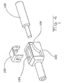
- a common method for fixing an optical waveguide in a carrier housing is the use of metal clips, as shown in Fig. 4.
- the carrier housing points here a receptacle 102 for the optical waveguide 122 and a receptacle for a metal clip 120 on.
- the optical waveguide 122 is positioned in the carrier housing 100 and through Inserting the metal clip 120 mechanically secured against axial displacement.
- a mechanical connector for optical fibers is known, the Comprises clamping elements and an elastic spring element.
- the optical fiber is in introduced a channel which is provided in an injection-molded plastic part.
- the Clamping device is movable in a direction transverse to the longitudinal axis of the optical fiber and is pressed by means of the spring element against the optical fiber.
- EP 0 290 188 A2 shows a connector for optical fibers with a housing which a base plate and three cover parts, wherein the three cover parts about Schamiere are connected to the base plate and locked in the assembled state with her can.
- the optical fiber is inserted in a V-shaped trench of the base plate and is mechanically fixed by the pressure of the lid parts.
- the object of the present invention is to provide a carrier housing for the connection an optical waveguide with an optical element to provide a possible simple and inexpensive attachment of optical fibers allowed.
- An essential feature of the carrier housing according to the invention for the compound an optical waveguide with an optical element is that the holding body made of the same material as the carrier housing. This can make the production of holding body and carrier housing take place in one and the same work step, which reduces production costs.
- the holding body is integral with the carrier housing and the holding body executed.
- the holding body has a receptacle for a plunger of a mounting tool. This will make the positioning facilitates the assembly tool and simplifies installation.
- the guide projections can be chamfered so that they the holding body fix in the assembled state by clamping.
- this offers the advantage of one secure stop during assembly and, on the other hand, allows the access to the fiber optic cable to keep acting forces as low as possible.
- optical waveguide which has a circular cross section, and is preferably made of plastic, is not shown in the drawings and is therefore not described in detail.
- optical elements to which the optical waveguide is to be coupled by means of the carrier housing not shown in the drawings for the sake of clarity.
- Such optical elements may, for example, be further optical fibers or a diode.
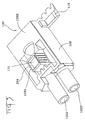
- the inventive Carrier housing 100 two substantially tubular receptacles 102A, 102B for the Recording the optical fiber.
- a holding body 104 made of the same material as the rest of the carrier housing is shown here in the preassembled state.
- Retaining webs 106 which made integral with the holding body and the carrier housing are, fix the holding body 104 in a position in which he is not in the insertion 102A and 102B protrudes. In this position, the optical fibers can therefore without Force are inserted into the insertion openings 102A, 102B.
- optical fibers correctly positioned such as via a guide and a stop inside the carrier housing can be ensured is about a plunger of a mounting tool, which is positioned in the receiving opening 110 is applied, a sufficiently high contact pressure in the direction of arrow 112, so that the holding webs 106 are broken, and the holding body 104 perpendicular to Insertion direction of the optical waveguide pushed into the insertion region 102A, 102B and with the toothed surfaces 108A, 108B the optical fibers by clamping fixed.
- the carrier housing 100 shown in Fig. 1 is a view from below shown. It can be seen the tubular receptacle 102A, 102B for the optical waveguide, which in Area of the toothed abutment surfaces 108A, 108B of the holding body 104 are open, so the optical waveguide is clamped after depression of the holding body 104 are.
- the holding web 106 which in an injection molding process with the holding body 104 and the Carrier housing 100 is made, must be dimensioned so that on the one hand ensures a secure fit of the holding body 104 in the preassembled state, on the other hand allows the holding body 104 with the lowest possible pressure in Direction 112 can be moved.
- Guide projections 115A, 115B ensure that the holding body 104 when pressed by an assembly tool exactly in the direction 112 moves perpendicular to the optical waveguide. As a stop that prevents that the holding body 104 is pushed too far in the direction 112, one can not here shown base surface of the mounting tool serve on which the bearing surface 114th continuous. However, it is also the side surfaces 116A and 116B of the guide projections Be tapered so that the holding body increases with increasing Clamping in the direction of 112 clamps.
- Figure 3 shows a carrier housing for the connection of two optical fibers with a optical component containing diodes according to a second preferred embodiment.
- the receptacles 102A, 102B for the optical waveguides are tubular Insertion aids continued to the outside.
- Side of the carrier housing 100 is a holder 118 for the recording of the optical component (not shown).
- the holding body 104 via integrally molded retaining webs 106 in the preassembled state attached to the carrier housing 100.
- a receiving opening 110 for a mounting tool allows the exact positioning of a Plunger, the holding body 104 for fixing the two optical fibers in the Recess openings 102A and 102B pushes.
- the carrier housing according to the invention could also be part of a "flying" coupling to Connecting several optical fiber ends to each other.
Landscapes
- Physics & Mathematics (AREA)
- General Physics & Mathematics (AREA)
- Optics & Photonics (AREA)
- Optical Couplings Of Light Guides (AREA)
- Mechanical Coupling Of Light Guides (AREA)
Description
In den Zeichnungen sind lediglich die aus einem Spritzgussmaterial, beispielsweise Kunststoff hergestellten Elemente des Trägergehäuses dargestellt. Der Lichtwellenleiter, der einen kreisförmigen Querschnitt aufweist, und vorzugsweise aus Kunststoff gefertigt ist, ist in den Zeichnungen nicht dargestellt und wird daher auch nicht näher beschrieben. Ebenso sind die optischen Elemente, an welche der Lichtwellenleiter mit Hilfe des Trägergehäuses angekoppelt werden soll, zur Wahrung der Übersichtlichkeit nicht in den Zeichnungen dargestellt. Solche optischen Elemente können beispielsweise weitere Lichtleitfasern oder eine Diode sein.
Claims (7)
- Trägergehäuse für die Aufnahme eines Lichtwellenleiters, wobei das Trägergehäuse (100) eine Aufnahme (102A, 102B) für den Lichtwellenleiter und einen Haltekörper (104), der formschlüssig in dem Trägergehäuse (100) aufgenommen wird und senkrecht zur Einführrichtung des Lichtwellenleiters bewegbar ist, aufweist, und wobei der Haltekörper (104) im vormontierten Zustand einstückig mit dem Trägergehäuse (100) ausgeführt ist und laus dem gleichen Material wie das Trägergehäuse (100) besteht und dadurch gekennzeichnet, dass der Haltekörper im vormontierten Zustand über einstückig ausgebildete Haltestege (106) an dem Trägergehäuse (100) angelagert ist, wobei die Haltestege derartig ausgebildet sind dass sie durch Anwendung eines Anpressdrucks gebrochen werden können
wobei das Trägergehäuse (100) Führungsvorsprünge (115) aufweist, entlang derer der Haltekörper in den fertig montierten Zustand (104) verschiebbar ist. - Trägergehäuse nach Anspruch 1, dadurch gekennzeichnet, dass der Haltekörper (104) an der mit dem Lichtwellenleiter in Anlage befindlichen Oberfläche (108A, 108B) eine Zahnung aufweist.
- Trägergehäuse nach einem der Ansprüche 1 oder 2, dadurch gekennzeichnet, dass der Haltekörper (104) eine Aufnahme (110) für einen Druckstempel eines Montagewerkzeugs aufweist.
- Trägergehäuse nach einem der Ansprüche 1 bis 3, dadurch gekennzeichnet, dass die Führungsvorsprünge (115) so abgeschrägt sind, dass der Haltekörper (104) im montierten Zustand durch Klemmung fixiert ist.
- Trägergehäuse nach einem der Ansprüche 1 bis 4, dadurch gekennzeichnet, dass an die Aufnahme (102A, 102B) als Verlängerung eine rohrförmige Einführhilfe angeformt ist.
- Trägergehäuse nach einem der Ansprüche 1 bis 5, dadurch gekennzeichnet, dass das Trägergehäuse zwei Aufnahmen (102A, 102B) aufweist, in die zwei Lichtwellenleiter im wesentlichen parallel zueinander einschiebbar sind und die Lichtwellenleiter durch denselben Haltekörper (104) fixierbar sind.
- Montageverfahren zur Montage mindestens eines Lichtwellenleiters an einem Trägergehäuse (100) mit den folgenden Schritten:wobei die Haltestege (106) durch das Verschieben des Haltekörpers (104) gebrochen werden und das Trägergehäuse (100) Führungsvorsprünge (115) aufweist, entlang derer der Haltekörper (104) senkrecht zur Einführrichtung des Lichtwellenleiters in den fertig montierten Zustand verschoben wird.Einführen des mindestens einen Lichtwellenleiters in eine Aufnahme (102A, 102B) des Trägergehäuses (100);Verschieben eines Haltekörpers (104), der im vormontierten Zustand einstückig mit dem Trägergehäuse (100) ausgeführt ist und aus dem gleichen Material wie das Trägergehäuse (100) besteht, von einer vormontierten Stellung, in welcher der Haltekörper (104) über einstückig ausgebildete Haltestege (106) an dem Trägergehäuse (100) angelagert ist, in eine fertig montierte Stellung, in welcher der Haltekörper (104) den mindestens einen Lichtwellenleiter mechanisch an dem Trägergehäuse (100) fixiert;
Applications Claiming Priority (2)
| Application Number | Priority Date | Filing Date | Title |
|---|---|---|---|
| DE10105070 | 2001-02-05 | ||
| DE10105070 | 2001-02-05 |
Publications (3)
| Publication Number | Publication Date |
|---|---|
| EP1229364A2 EP1229364A2 (de) | 2002-08-07 |
| EP1229364A3 EP1229364A3 (de) | 2003-07-16 |
| EP1229364B1 true EP1229364B1 (de) | 2005-01-05 |
Family
ID=7672854
Family Applications (1)
| Application Number | Title | Priority Date | Filing Date |
|---|---|---|---|
| EP01125879A Expired - Lifetime EP1229364B1 (de) | 2001-02-05 | 2001-10-30 | Trägergehäuse für einen Lichtwellenleiter |
Country Status (4)
| Country | Link |
|---|---|
| US (1) | US6793404B2 (de) |
| EP (1) | EP1229364B1 (de) |
| JP (1) | JP3919552B2 (de) |
| DE (1) | DE50105025D1 (de) |
Families Citing this family (9)
| Publication number | Priority date | Publication date | Assignee | Title |
|---|---|---|---|---|
| GB2416927A (en) * | 2004-07-29 | 2006-02-08 | Itt Mfg Enterprises Inc | Cable Clamp |
| US7534050B2 (en) | 2007-04-13 | 2009-05-19 | Adc Telecommunications, Inc. | Field terminatable fiber optic connector assembly |
| WO2009045562A1 (en) | 2007-04-13 | 2009-04-09 | Adc Telecommunications, Inc. | Optical fiber field termination kit |
| WO2009073500A1 (en) | 2007-11-30 | 2009-06-11 | Adc Telecommunications, Inc. | Hybrid fiber/copper connector system and method |
| DE102009028595B4 (de) * | 2009-08-17 | 2018-04-05 | Te Connectivity Germany Gmbh | Anschlussvorrichtung für einen Lichtwellenleiter |
| US8646813B1 (en) * | 2010-04-08 | 2014-02-11 | Sami Shemtov | Electrical conduit connector with two-point engagement |
| US8636425B2 (en) | 2011-03-15 | 2014-01-28 | Adc Telecommunications, Inc. | Fiber optic connector |
| WO2013117589A2 (en) | 2012-02-07 | 2013-08-15 | Tyco Electronics Raychem Bvba | Cable termination assembly and method for connectors |
| US9176285B2 (en) | 2012-05-03 | 2015-11-03 | Adc Telecommunications, Inc. | Fiber optic connector |
Family Cites Families (12)
| Publication number | Priority date | Publication date | Assignee | Title |
|---|---|---|---|---|
| US4211462A (en) * | 1979-01-22 | 1980-07-08 | Stewart Stamping Corporation, A Division Of Insilco Corp. | Electrical connector for termination cords with improved locking means |
| US4327964A (en) * | 1979-12-20 | 1982-05-04 | Texas Instruments Incorporated | Snap-action fiber optic connector |
| US4735477A (en) * | 1984-12-11 | 1988-04-05 | Amp Incorporated | Fiber optic splice terminal and method of using same |
| WO1987003969A1 (en) * | 1985-12-26 | 1987-07-02 | Amp Incorporated | Optical fiber connector |
| FR2593294B1 (fr) * | 1986-01-23 | 1990-01-05 | Alsthom Cgee | Connecteur pour fibres optiques |
| US4730892A (en) * | 1986-03-17 | 1988-03-15 | Northern Telecom Limited | Optical fiber mechanical splice |
| US4784456A (en) * | 1987-05-06 | 1988-11-15 | E. I. Du Pont De Nemours And Company | Fiber optic connector |
| US5013123A (en) * | 1988-04-18 | 1991-05-07 | Minnesota Mining And Manufacturing Company | Stamped precision lightguide interconnect centering element |
| US5133033A (en) * | 1990-05-31 | 1992-07-21 | Northern Telecom Limited | Optical fiber mechanical splice and method for its use |
| US5717813A (en) * | 1994-06-27 | 1998-02-10 | Fiberlign A Division Of Preformed Line Products (Canada) Ltd. | Fusion splice element for use in splicing optical fibers |
| JP3120361B2 (ja) * | 1995-10-26 | 2000-12-25 | モレックス インコーポレーテッド | 光ファイバーケーブル用コネクタ |
| FR2757959B1 (fr) * | 1996-12-30 | 1999-01-22 | Alsthom Cge Alcatel | Module d'epissure pour fibres optiques |
-
2001
- 2001-10-30 DE DE50105025T patent/DE50105025D1/de not_active Expired - Lifetime
- 2001-10-30 EP EP01125879A patent/EP1229364B1/de not_active Expired - Lifetime
-
2002
- 2002-02-04 US US10/067,688 patent/US6793404B2/en not_active Expired - Lifetime
- 2002-02-05 JP JP2002027536A patent/JP3919552B2/ja not_active Expired - Fee Related
Also Published As
| Publication number | Publication date |
|---|---|
| US6793404B2 (en) | 2004-09-21 |
| JP2002258106A (ja) | 2002-09-11 |
| EP1229364A3 (de) | 2003-07-16 |
| US20020154868A1 (en) | 2002-10-24 |
| EP1229364A2 (de) | 2002-08-07 |
| DE50105025D1 (de) | 2005-02-10 |
| JP3919552B2 (ja) | 2007-05-30 |
Similar Documents
| Publication | Publication Date | Title |
|---|---|---|
| EP2104190B1 (de) | Adapter zur Aufnahme eines Steckerteiles | |
| EP1775612B1 (de) | Optische Kabelanschlussvorrichtung | |
| EP1860473B1 (de) | Optischer Stecker mit einem in seinem Trägerteil einrastbaren und längsverschiebaren Halteteil | |
| DE69223963T2 (de) | Optische faser verbindungsanlage | |
| DE69603733T2 (de) | Faseroptisches verbindungselement | |
| DE19515795C2 (de) | Lichtwellenleiterverbinder | |
| DE69322977T2 (de) | Optischer stecker | |
| DE69917328T2 (de) | Faseroptischer Verbinder in dem eine optische Faser auch dann geschützt wird, wenn die Verbindung nicht hergestellt ist | |
| WO2003093889A1 (de) | Kupplung für glasfaserverbinder mit nachrüstbarer sicherheitsklappe | |
| DE69833915T2 (de) | Mehrere Faser Spleisselement und Stecker | |
| EP1229364B1 (de) | Trägergehäuse für einen Lichtwellenleiter | |
| DE69735232T2 (de) | Feder für einen faseroptischen verbinder | |
| DE3517388C2 (de) | ||
| DE10255100B4 (de) | Optischer Verbinder und Anordnung zum Halten einer optischen Faserleitung | |
| DE19533296C2 (de) | Befestigungsvorrichtung für Lichtwellenleiter | |
| DE4406154C2 (de) | Aufnahme mit Knickschutz für einen Faserspleiß | |
| EP3255472B1 (de) | Kabelzugabfangelement | |
| DE19904445A1 (de) | Linsenstecker zum Aufbau kompakter Freistrahlanordnungen für mehrere Lichtleitfasern | |
| DE19851867C2 (de) | Vorrichtung zur lösbaren Verbindung von Lichtwellenleitern miteinander oder mit elektrooptischen Sende- und/oder Empfangseinrichtungen | |
| AT407927B (de) | Kombinierter lichtwellenleiter-/metallkabel- steckverbinder | |
| DE102011005114B4 (de) | Gehäuse für einen Sensor, Sensormodul mit diesem Gehäuse und Herstellungsverfahren für dieses Gehäuse | |
| EP1152271A2 (de) | LWL-Klemme | |
| DE19840442C2 (de) | Steckvorrichtung für einen Lichtwellenleiter | |
| DE60210982T2 (de) | Vorrichtung und verfahren zum verbinden einer optischen faser | |
| DE202005011459U1 (de) | Verteilereinrichtung |
Legal Events
| Date | Code | Title | Description |
|---|---|---|---|
| PUAI | Public reference made under article 153(3) epc to a published international application that has entered the european phase |
Free format text: ORIGINAL CODE: 0009012 |
|
| AK | Designated contracting states |
Kind code of ref document: A2 Designated state(s): AT BE CH CY DE DK ES FI FR GB GR IE IT LI LU MC NL PT SE TR |
|
| AX | Request for extension of the european patent |
Free format text: AL;LT;LV;MK;RO;SI |
|
| PUAL | Search report despatched |
Free format text: ORIGINAL CODE: 0009013 |
|
| AK | Designated contracting states |
Designated state(s): AT BE CH CY DE DK ES FI FR GB GR IE IT LI LU MC NL PT SE TR |
|
| AX | Request for extension of the european patent |
Extension state: AL LT LV MK RO SI |
|
| RIC1 | Information provided on ipc code assigned before grant |
Ipc: 7G 02B 6/36 A Ipc: 7G 02B 6/38 B |
|
| 17P | Request for examination filed |
Effective date: 20030905 |
|
| 17Q | First examination report despatched |
Effective date: 20031113 |
|
| AKX | Designation fees paid |
Designated state(s): DE FR GB IT |
|
| GRAP | Despatch of communication of intention to grant a patent |
Free format text: ORIGINAL CODE: EPIDOSNIGR1 |
|
| GRAS | Grant fee paid |
Free format text: ORIGINAL CODE: EPIDOSNIGR3 |
|
| GRAA | (expected) grant |
Free format text: ORIGINAL CODE: 0009210 |
|
| AK | Designated contracting states |
Kind code of ref document: B1 Designated state(s): DE FR GB IT |
|
| REG | Reference to a national code |
Ref country code: GB Ref legal event code: FG4D Free format text: NOT ENGLISH |
|
| REG | Reference to a national code |
Ref country code: IE Ref legal event code: FG4D Free format text: GERMAN |
|
| REF | Corresponds to: |
Ref document number: 50105025 Country of ref document: DE Date of ref document: 20050210 Kind code of ref document: P |
|
| GBT | Gb: translation of ep patent filed (gb section 77(6)(a)/1977) |
Effective date: 20050414 |
|
| PLBE | No opposition filed within time limit |
Free format text: ORIGINAL CODE: 0009261 |
|
| STAA | Information on the status of an ep patent application or granted ep patent |
Free format text: STATUS: NO OPPOSITION FILED WITHIN TIME LIMIT |
|
| 26N | No opposition filed |
Effective date: 20051006 |
|
| ET | Fr: translation filed | ||
| REG | Reference to a national code |
Ref country code: GB Ref legal event code: FG4D Free format text: NOT ENGLISH |
|
| REG | Reference to a national code |
Ref country code: DE Ref legal event code: R081 Ref document number: 50105025 Country of ref document: DE Owner name: TE CONNECTIVITY GERMANY GMBH, DE Free format text: FORMER OWNER: TYCO ELECTRONICS AMP GMBH, 64625 BENSHEIM, DE |
|
| REG | Reference to a national code |
Ref country code: FR Ref legal event code: PLFP Year of fee payment: 15 |
|
| REG | Reference to a national code |
Ref country code: FR Ref legal event code: CD Owner name: TE CONNECTIVITY GERMANY GMBH Effective date: 20151027 |
|
| REG | Reference to a national code |
Ref country code: FR Ref legal event code: PLFP Year of fee payment: 16 |
|
| REG | Reference to a national code |
Ref country code: FR Ref legal event code: PLFP Year of fee payment: 17 |
|
| PGFP | Annual fee paid to national office [announced via postgrant information from national office to epo] |
Ref country code: FR Payment date: 20171025 Year of fee payment: 17 Ref country code: DE Payment date: 20171027 Year of fee payment: 17 |
|
| PGFP | Annual fee paid to national office [announced via postgrant information from national office to epo] |
Ref country code: GB Payment date: 20171027 Year of fee payment: 17 Ref country code: IT Payment date: 20171024 Year of fee payment: 17 |
|
| REG | Reference to a national code |
Ref country code: DE Ref legal event code: R119 Ref document number: 50105025 Country of ref document: DE |
|
| GBPC | Gb: european patent ceased through non-payment of renewal fee |
Effective date: 20181030 |
|
| PG25 | Lapsed in a contracting state [announced via postgrant information from national office to epo] |
Ref country code: DE Free format text: LAPSE BECAUSE OF NON-PAYMENT OF DUE FEES Effective date: 20190501 |
|
| PG25 | Lapsed in a contracting state [announced via postgrant information from national office to epo] |
Ref country code: FR Free format text: LAPSE BECAUSE OF NON-PAYMENT OF DUE FEES Effective date: 20181031 |
|
| PG25 | Lapsed in a contracting state [announced via postgrant information from national office to epo] |
Ref country code: GB Free format text: LAPSE BECAUSE OF NON-PAYMENT OF DUE FEES Effective date: 20181030 Ref country code: IT Free format text: LAPSE BECAUSE OF NON-PAYMENT OF DUE FEES Effective date: 20181030 |