EP1229449B1 - Diagnostic à distance de dispositifs - Google Patents
Diagnostic à distance de dispositifs Download PDFInfo
- Publication number
- EP1229449B1 EP1229449B1 EP01102230A EP01102230A EP1229449B1 EP 1229449 B1 EP1229449 B1 EP 1229449B1 EP 01102230 A EP01102230 A EP 01102230A EP 01102230 A EP01102230 A EP 01102230A EP 1229449 B1 EP1229449 B1 EP 1229449B1
- Authority
- EP
- European Patent Office
- Prior art keywords
- communication protocol
- home network
- interface
- communication
- remote
- Prior art date
- Legal status (The legal status is an assumption and is not a legal conclusion. Google has not performed a legal analysis and makes no representation as to the accuracy of the status listed.)
- Expired - Lifetime
Links
Images


Classifications
-
- H—ELECTRICITY
- H04—ELECTRIC COMMUNICATION TECHNIQUE
- H04L—TRANSMISSION OF DIGITAL INFORMATION, e.g. TELEGRAPHIC COMMUNICATION
- H04L43/00—Arrangements for monitoring or testing data switching networks
- H04L43/50—Testing arrangements
-
- G—PHYSICS
- G06—COMPUTING OR CALCULATING; COUNTING
- G06F—ELECTRIC DIGITAL DATA PROCESSING
- G06F11/00—Error detection; Error correction; Monitoring
- G06F11/22—Detection or location of defective computer hardware by testing during standby operation or during idle time, e.g. start-up testing
- G06F11/2294—Detection or location of defective computer hardware by testing during standby operation or during idle time, e.g. start-up testing by remote test
-
- H—ELECTRICITY
- H04—ELECTRIC COMMUNICATION TECHNIQUE
- H04L—TRANSMISSION OF DIGITAL INFORMATION, e.g. TELEGRAPHIC COMMUNICATION
- H04L12/00—Data switching networks
- H04L12/28—Data switching networks characterised by path configuration, e.g. LAN [Local Area Networks] or WAN [Wide Area Networks]
- H04L12/2803—Home automation networks
- H04L12/2805—Home Audio Video Interoperability [HAVI] networks
-
- H—ELECTRICITY
- H04—ELECTRIC COMMUNICATION TECHNIQUE
- H04L—TRANSMISSION OF DIGITAL INFORMATION, e.g. TELEGRAPHIC COMMUNICATION
- H04L12/00—Data switching networks
- H04L12/28—Data switching networks characterised by path configuration, e.g. LAN [Local Area Networks] or WAN [Wide Area Networks]
- H04L12/2803—Home automation networks
- H04L12/2816—Controlling appliance services of a home automation network by calling their functionalities
- H04L12/2821—Avoiding conflicts related to the use of home appliances
-
- H—ELECTRICITY
- H04—ELECTRIC COMMUNICATION TECHNIQUE
- H04L—TRANSMISSION OF DIGITAL INFORMATION, e.g. TELEGRAPHIC COMMUNICATION
- H04L12/00—Data switching networks
- H04L12/28—Data switching networks characterised by path configuration, e.g. LAN [Local Area Networks] or WAN [Wide Area Networks]
- H04L12/40—Bus networks
- H04L12/40052—High-speed IEEE 1394 serial bus
- H04L12/40097—Interconnection with other networks
-
- H—ELECTRICITY
- H04—ELECTRIC COMMUNICATION TECHNIQUE
- H04L—TRANSMISSION OF DIGITAL INFORMATION, e.g. TELEGRAPHIC COMMUNICATION
- H04L12/00—Data switching networks
- H04L12/64—Hybrid switching systems
- H04L12/6418—Hybrid transport
-
- H—ELECTRICITY
- H04—ELECTRIC COMMUNICATION TECHNIQUE
- H04L—TRANSMISSION OF DIGITAL INFORMATION, e.g. TELEGRAPHIC COMMUNICATION
- H04L12/00—Data switching networks
- H04L12/28—Data switching networks characterised by path configuration, e.g. LAN [Local Area Networks] or WAN [Wide Area Networks]
- H04L12/2803—Home automation networks
- H04L12/2816—Controlling appliance services of a home automation network by calling their functionalities
- H04L12/2818—Controlling appliance services of a home automation network by calling their functionalities from a device located outside both the home and the home network
Definitions
- the invention relates to a method for communicating between a remote testing device and an IEEE 1394-2000 home network device, and to a remote testing device, a communication protocol interface and a service diagnosting system necessary to perform said method.
- the home network usually comprises a gateway which can be contacted by a remote testing device being connected via a remote communication network like the internet to the gateway.
- the gateway acts like an interface to translate commands sent by the remote testing device into appropriate home network commands, which are then sent to the respective home network devices.
- the remote testing device usually establishes a TCP/IP connection over the remote communication network to communicate with the gateway. Then, a browser software installed on the remote testing device can use the established TCP/IP connection to communicate with the gateway.
- the gateway extracts communication information sent by the browser software via TCP/IP from the TCP/IP protocol and encapsulates the extracted communication information into a home network protocol being used by the respective home network device, like AV/C. Finally, the communication information is sent by the gateway via AV/C to the respective home network device to control it.
- the communication is on a remote communication protocol basis between the remote testing device and the communication protocol interface, and vice-versa, said communication protocol interface being part of the home network.
- the communication protocol interface is constituted by a SNMP proxy in cooperation with a SNMP master agent inside within the home network.
- the communication protocol interface (SNMP proxy) also transfers information contained in frames of the remote communication protocol using the Transmission Control Protocol TCP as opposed to the User Datagram protocol/internet Protocol UDP/IP inside the home network.
- the present invention provides a method for communicating between a remote testing device and an IEEE 1394 home network device being located in a home network, wherein said remote testing device is connected with said home network via a remote communication network, which is characterized by communicating on a remote communication protocol basis between said remote testing device and a communication protocol interface which is part of said home network, and communicating on an IEEE 1394 low level communication protocol basis between said communication protocol interface and said IEEE 1394 home network device.
- the present invention provides a communication protocol interface being a part of a home network for transferring communication information encapsulated within a first/second communication protocol frame into a second/first communication protocol frame, which is characterized by a first IEEE 1394 interface, functionality for extracting device status information from an IEEE 1394 supporting home network device via said first IEEE 1394 interface and an IEEE 1394 connection linking said IEEE 1394 supporting home network device to said first IEEE 1394 interface by using a low level communication protocol frame of said first IEEE 1394 interface a said first communication protocol frame, and a remote communication protocol interface and functionality for communicating with a remote testing device via said remote communication protocol interface and a remote communication network linking said remote testing device to said remote communication protocol interface by using said second communication protocol frame.
- the present invention provides a remote testing device for extracting device status information of an IEEE 1394 home network device being located in a home network, wherein said remote testing device is connected with said home network via a remote communication network, which is characterized by means for encapsulating/decapsulating communication information from/into a communication protocol frame, and means for sending/receiving said communication protocol frame via said remote communication network to/from said IEEE 1394 home network deivce by using a remote communication protocol.
- the present invention provides a service diagnostic system, which comprises
- An important aspect of the present invention is that a communication method is employed which uses IEEE1394 functionality within the home network, but which is independent of any home network communication protocol or environment. This is realized by using IEEE 1394 low level base mechanisms of asynchronous read and write transactions which are underlying all home network communication protocols employed by IEEE1394 supporting devices. Preferably, a Quadlet read/write protocol is used. Thus, one single communication protocol is sufficient to contact all home network devices within the home network.
- the IEEE1394 low level base communication mechanisms will be referred to as service diagnostic interface communication protocol (SDI communication protocol), which has been described in the applicants parallel European patent application "Device Diagnostics" which content is herewith incorporated into this specification.
- the communication between the remote testing device and the home network device can be split into at least two communication sections.
- the first communication section consists of a remote communication network between the remote testing device and the communication protocol interface which is part of the home network.
- the communication via the first communication section is done by using a remote communication protocol like TCP/IP.
- the second communication section consists of an IEEE 1394 connection like an IEEE 1394 serial bus between the communication protocol interface and the home network device which has to be diagnosted by the remote testing device.
- the communication via the second communication section is done by using the SDI communication protocol.
- the communication protocol interface may consist of hardware and/or software, and may be located/represented in a gateway connecting the home network to the remote communication network. However, the communication protocol interface may also be "distributed" over several devices within the home network. For example, a first unit of the communication protocol interface may be located in a gateway, and a second unit may be located in a proxy. The gateway and the proxy may be connected with each other via an IEEE1394 connection. In this case, the communication between the remote testing device and the home network device can be split into at least three communication sections.
- the first communication section consists of a connection between the remote testing device and the communication protocol interface
- the second communication section consists of an IEEE 1394 connection within the communication protocol interface between its first unit and its second unit
- the third communication section consists of an IEEE1394 connection between the second unit of the communication network and the home network device.
- the communication via the second section is preferably done by using the home network communication protocol like AV/C (audio video/ control).
- the gateway acts as an interface between the communication protocol used to transport communication information via the first communication section, and the communication protocol applied over the following second communication section, which may be the home network communication protocol, or the SDI communication protocol.
- the communication information is preferably transported within the home network on a home network protocol basis via the second communication section to the proxy, which extracts the communication information from the home network communication protocol.
- the proxy analyzes the communication information and starts to communicate with the home network device via the third communication section by using the SDI communication protocol.
- the proxy may generate new communication information according to a result of the analyzing process of the received communication information and send this generated communication information to the home network device.
- the proxy may just encapsulate the received, decapsulated communication information unchanged into the SDI communication protocol.
- the capability of the proxy to analyze and to generate communication information makes it possible to "instruct" the proxy how to communicate with the home network device by sending communication information to the proxy.
- the proxy may initiate selftests within the home network device, or read out device-specific information according to instructions received in form of communication information.
- the proxy After having extracted the device status information, the proxy encapsulates the extracted device status information as communication information into the home network communication protocol and sends it via the second communication section back to the gateway, which transfers the communication information into the remote communication protocol and sends it back to the remote testing device.
- An advantage of this communication mechanism is that it is sufficient to provide only one TCP/IP supporting device within the home network which supports a remote communication protocol like TCP/IP.
- the proxy itself does only have to support the home network communication protocol like AV/C, which is likely to be supported by the proxy anyhow.
- the remote testing device does only have to send command information instructing the communication protocol interface to extract device status information from the home network device to the communication protocol interface.
- the extraction process of the device status information is then organized by the communication protocol interface itself.
- the resulting data is sent back to the remote testing device in one single communication transaction.
- the communication via the first communication section is very simple, as it may comprise only one single instruction command sent by the remote testing device to the communication protocol interface and and one single sending transaction of extracted device status information from the communication protocol interface to the remote testing device.
- the advantage thereof is that the remote testing device does not necessarily have to comprise SDI communication protocol functionality, but nevertheless is capable of communicating with all home network devices.
- the SDI communication protocol functionality is preferably completely located within the communication protocol interface.
- the communication information to be sent by the remote testing device may first be wrapped into a home network communication protocol frame, before sending the home network communication protocol frame via the remote communication protocol to the communication protocol interface.
- a communication protocol interface would then only have to extract the home network communication protocol frame, and send the frame unchanged to the proxy.
- extracted device status information may be first wrapped into a home network communication protocol frame before transporting the frame via the remote communication protocol to the remote testing device.
- the proxy is located within the gateway itself, it may be advantageous to wrap communication information into a SDI communication protocol frame before transporting this frame via the remote communication protocol to the gateway, and the gateway could directly extract the SDI communication protocol frame from the remote communication protocol and send this frame directly to the home network device.
- the translation of the communication information into the home network communication protocol can be left, as it is not necessary to transport the communication information within the home network to the proxy, which would make it necessary to encapsulate command information within a home network protocol frame.
- communication information is first wrapped into a SDI communication protocol frame, wherein this frame is then wrapped itself into a home network communication protocol frame, and the home network communication protocol frame is then sent by using the remote communication protocol.
- This embodiment may be used in case of a distributed communication protocol interface, where the proxy comprises no functionality to analyze and generate communication information. The only task of the proxy would be to decapsulate/encapsulate the SDI communication protocol frame from/into the home network communication protcol frame and to send/receive the SDI communication protocol frame to/from the home network device.
- the clear separation of the device status information extracting process which is completely managed by the proxy, or, to be more general, by the communication protocol interface, and the communication between the remote testing device and the proxy (communication protocol interface) has the advantage that the characteristics of the SDI communication process that make this process impractical for direct use as the remote diagnosis protocol can be encapsulated within the home network protocol. That is, after a selftest of the home network device has been initiated by the proxy, the proxy has to continuously poll-read response code registers within the home network device until the device has completed the selftest, which could in practice take several seconds to complete. This mechanism however, is not suitable to be done from remote. The remote testing device does not have to continuously poll-read, but only receives extracted device status information after the extraction process has been entirely finished.
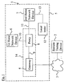
- a service diagnostic system 1 comprises a remote testing device 2, which is connected via a remote communication network 3 to a gateway 4.
- the gateway 4 is part of a home network 5, which comprises a first home network device 6 and a second home network device 7.
- the home network 5 further comprises a proxy 8 being connected to the gateway 4 via a first IEEE1394 serial bus 9.
- the proxy 8 is further connected to the first home network device 6 via a second IEEE1394 serial bus 10, and to the second home network device via a third IEEE1394 serial bus 11.
- the home network 5 may further comprise a local tester 12 being connected to the second home network device 7 via a fourth IEEE1394 serial bus 13.
- the sum of the gateway 4, the proxy 8 and the first IEEE 1394 serial bus 9 may be regarded as a communication protocol interface 14.
- a communication protocol interface 14 comprises a first unit 15 and a second unit 16, which are connected via an IEEE 1394 connection 17.
- the first unit 15 comprises a remote communication protocol interface 18 and a first IEEE 1394 communication protocol interface 19.
- the first unit 15 further comprises functionality for extracting/encapsulating a home network communication protocol frame from/into a remote communication protocol.
- the second unit 16 comprises a first IEEE 1394 interface 20 for communicating with the first unit 15 and for communicating with the home network devices 6, 7.
- the second unit 16 further comprises functionality for extracting/encapsulating a SDI communication protocol frame from/into a home network communication protocol frame, and for interpreting received command information and functionality for controlling a SDI device status information extraction process of the home network devices 6, 7 being connected to the second unit 16 via the first IEEE 1394 interface 20 and the second and the third IEEE 1394 serial bus 10, 11. respectively.
- the first unit 15 may be regarded as the gateway 4, the second unit 16 may be regarded as the proxy 8, and the IEEE 1394 connection 17 may be regarded as the first IEEE 1394 serial bus 9.
- a test command to the communication protocol interface 14, (which is represented in Fig. 3 by an EACEM (European Association of Consumer Electronic Manufacturers)-SDI home network proxy) which interprets a command, and initiates in a step S2 a self test inside a home network device 6, 7 (which is represented in Fig. 3 by an EACEM-SDI-DUT ( D evice which is U nder T est)) by using the SDI communication protocol.
- the communication protocol interface 14 polls at preferably regular time intervals (steps S3 1 to S3 n ) if the self test within the home network device has already been completed.
- step S4 the return code of the self test routine is read in a step S4 .
- step S5 a text message is read from the device 6, 7.
- the text message and the return code are collected as extracted device status information and are sent back to the remote testing device 2 by a single communication transaction in step S6.
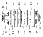
- a remote testing application 21 running on a remote testing device 2 generates communication information in a first step S10, and wraps the communication information in a second step S11 into a home network communication protocol frame.
- the home network communication protocol frame is encapsulated within a remote communication protocol, for example TCP/IP.
- the home network communication protocol frame is transported via the remote communication protocol to the communication protocol interface 14, which decapsulates in a fifth step S14 the home network communication protocol frame from the remote communication protocol.
- the home network communication protocol frame is sent to the proxy 8, which in a seventh step S15 extracts command information from the home network communication protocol frame.
- the proxy processes the command information and generates in an eighth step S16 appropriate SDI communication protocol frames containing command information for the home network device 22.
- the proxy After having extracted device status information from the home network device 22 using the SDI communication protocol in a ninth step S17, the proxy encapsulates the extracted information in a tenth step S18 into a home network communication protocol frame and sends it back to the gateway 4, which in an eleventh step S19 encapsulates the home network communication protocol frame into the remote communication protocol.
- the home network communication protocol frame is sent in a twelfth step S20 via the remote communication protocol to the remote testing device 21, which decapsulates in an thirteenth step S21 the home network communication protocol frame from the remote communication protocol, and further extracts the device status information in a fourteenth step S22 from the home network communication protocol frame.
- the proxy 8 In order to communicate between the gateway 4 and the proxy 8, it is necessary that the proxy 8 can be accessed by an API (application program interface).
- API application program interface
- the proxy API should show the following input- and output parameters:
- the input parameters necessary for initiating a test in a home network device 6. 7 are
- the output parameters containing extracted device status information are
- AV/C home network protocol
- the proxy 8 should provide a new SDI FCM as API (function control module) in its DCM (device control module).
- SDI FCM function control module
- DCM device control module
- DiagProxy::ExecTest Prototype Status DiagProxy::ExecTest(in TestCode testCode, out TestResponseCode respCode, out wstring testResponseText)
- Parameters _ testCode - identifies the test to be performed _ testResponseCode- the code returned by the target device _ testResponseText - the corresponding text
- DiagProxy::ExecTest initiates the given test, indicated by the testCode argument, in the target device. Error codes _ DiagProxy::ENOT_??? - the ...
- DiagProxy::GetStatus Prototype Status DiagProxy::GetStatus(out TestResponseCode respCode, out wstring testResponseText) Parameters _ testResponseCode - the code returned by the target device _ testResponseText - the corresponding text Description
- DiagProxy::GetStatus retrieves the diagnostic status of the target device without initiating any test command. Error codes _ DiagProxy::ENOT_??? - the ...
Landscapes
- Engineering & Computer Science (AREA)
- Computer Networks & Wireless Communication (AREA)
- Signal Processing (AREA)
- Automation & Control Theory (AREA)
- General Engineering & Computer Science (AREA)
- Theoretical Computer Science (AREA)
- Physics & Mathematics (AREA)
- General Physics & Mathematics (AREA)
- Quality & Reliability (AREA)
- Computer Security & Cryptography (AREA)
- Computer Hardware Design (AREA)
- Multimedia (AREA)
- Small-Scale Networks (AREA)
- Maintenance And Management Of Digital Transmission (AREA)
- Computer And Data Communications (AREA)
Claims (20)
- Procédé de communication entre un dispositif de test à distance (2) et un dispositif de réseau domestique IEEE1394 (6, 7) qui est situé dans un réseau domestique (5), dans lequel ledit dispositif de test à distance (2) est connecté audit réseau domestique (5) par l'intermédiaire d'un réseau de communication à distance (3), caractérisé par ledit procédé comprenant les étapes consistant à :- communiquer sur la base d'un protocole de communication à distance entre ledit dispositif de test à distance (2) et une interface de protocole de communication (14) qui fait partie dudit réseau domestique (5) en transférant des informations de communication encapsulées à l'intérieur d'une première/seconde trame de protocole de communication dans une seconde/première trame de protocole de communication.- communiquer sur une base de protocole de communication IEEE1394 entre ladite interface de protocole de communication (14) et ledit dispositif de réseau domestique IEEE1394 (6,7), ladite interface de protocole de communication (14) comprenant une fonctionnalité pour extraire des informations d'état de dispositif à partir du dispositif de réseau domestique acceptant la norme IEEE1394 (6, 7) par l'intermédiaire d'une première interface IEEE1394 (20) et d'une connexion IEEE1394 (10, 11) reliant ledit premier dispositif de réseau domestique acceptant la norme IEEE1394 à ladite première interface IEEE1394 (20) en utilisant une trame de protocole de communication de ladite première interface IEEE1394 (20) en tant que première trame de protocole de communication.- où les informations d'état de dispositif de réseau domestique devant être transférées dudit dispositif de réseau domestique IEEE1394 (6, 7) audit dispositif de test à distance sont transférées dudit dispositif de réseau domestique IEEE1394 (6, 7) à ladite interface de protocole de communication (14) en utilisant un mécanisme d'interrogation-lecture qui effectue régulièrement une interrogation pour savoir si le test à l'intérieur du dispositif de réseau domestique (6, 7) s'est achevé et, lorsque le test s'est achevé, transfère alors lesdites informations d'état de dispositif extraites en une seule transaction de communication de ladite interface de protocole de communication (14) audit dispositif de test à distance (2).
- Procédé selon la revendication 1, comprenant :- l'encapsulation/la désencapsulation d'informations de communication dans/depuis une trame de protocole de communication, avant/après- le transport de ladite trame de protocole de communication entre ledit dispositif de test à distance (2) et ladite interface de protocole de communication (14) sur ladite base de protocole de communication à distance.
- Procédé selon la revendication 2, comprenant :- l'encapsulation/la désencapsulation desdites informations de communication dans/depuis une trame de protocole de communication de réseau domestique.
- Procédé selon la revendication 2, comprenant :- l'encapsulation/la désencapsulation desdites informations de communication dans/depuis une trame de protocole de communication de bas niveau IEEE1394.
- Procédé selon la revendication 4, comprenant :- l'encapsulation/la désencapsulation de ladite trame de protocole de communication de bas niveau IEEE1394 dans/depuis une trame de protocole de communication de réseau domestique.
- Procédé selon la revendication 3 ou 5, comprenant le transport d'une trame de protocole de communication de réseau domestique désencapsulée/générée par ladite interface de protocole de communication (14) à l'intérieur de ladite interface de protocole de communication (14) avant le transfert des informations de communication contenues à l'intérieur de ladite trame de protocole de communication de réseau domestique dans une trame de protocole de communication IEEE1394 ou avant le transport de ladite trame de protocole de communication entre ledit dispositif de test à distance (2) et ladite interface de protocole de communication (14) sur ladite base de protocole de communication à distance.
- Procédé selon l'une quelconque des revendications précédentes, comprenant l'envoi d'instructions en tant qu'informations de communication par l'intermédiaire dudit réseau de communication à distance (3) dudit dispositif de test à distance (2) à ladite interface de protocole de communication pour donner pour instruction à ladite interface de protocole de communication (14) la manière de communiquer avec ledit dispositif de réseau domestique (6, 7) sur ladite base de protocole de communication IEEE1394.
- Procédé selon la revendication 7, comprenant l'extraction d'informations d'état de dispositif à partir dudit dispositif de réseau domestique (6, 7) sur la base dudit traitement de communication IEEE1394 entre ledit dispositif de réseau domestique (6, 7) et ladite interface de protocole de communication (14) conformément auxdites instructions envoyées par ledit dispositif de test à distance (2).
- Procédé selon la revendication 8 comprenant l'envoi d'informations d'état de dispositif extraites en tant qu'informations de communication par l'intermédiaire dudit réseau de communication à distance (3) de ladite interface de protocole de communication (14) audit dispositif de test à distance (2), dans lequel ledit traitement d'envoi desdites informations d'état de dispositif extraites est exécuté seulement après que ledit traitement d'extraction d'informations d'état de dispositif a été achevé conformément auxdites instructions dudit dispositif de test à distance (2).
- Procédé selon l'une quelconque des revendications précédentes, comprenant l'utilisation d'un protocole TCP/IP en tant que protocole de communication à distance.
- Procédé selon l'une quelconque des revendications précédentes, comprenant l'utilisation d'un protocole de lecture/écriture Quadlet en tant que protocole de communication IEEE1394.
- Procédé selon l'une quelconque des revendications précédentes, comprenant l'utilisation d'un protocole AV/C ou d'un protocole HAVi en tant que ledit protocole de communication de réseau domestique.
- Interface de protocole de communication (14) faisant partie d'un réseau domestique (5) destiné à transférer des informations de communication encapsulées à l'intérieur d'une première/seconde trame de protocole de communication dans une seconde/première trame de protocole de communication, comprenant :- une première interface IEEE1394 (20), et- une fonctionnalité destinée à extraire des informations d'état du dispositif à partir d'un dispositif de réseau domestique acceptant le protocole IEEE1394 (6, 7) par l'intermédiaire de ladite première interface IEEE1394 (20) et d'une connexion IEEE1394 (10, 11) reliant ledit dispositif de réseau domestique acceptant le protocole IEEE1394 (6, 7) à ladite première interface IEEE1394 (20) en utilisant une trame de protocole de communication de ladite première interface IEEE1394 (20) en tant que première trame de protocole de communication, où ladite fonctionnalité d'extraction comprend une fonctionnalité d'interrogation-lecture destinée à transférer des informations d'état de dispositif de réseau domestique dudit dispositif de réseau domestique acceptant le protocole IEEE1394 (6, 7) à ladite interface de protocole de communication (14) en utilisant un mécanisme d'interrogation-écriture identique à celui de la revendication 1 et transfère ensuite lesdites informations d'état de dispositif extraites audit dispositif de test à distance,- une interface de protocole de communication à distance (18) et une fonctionnalité pour communiquer avec un dispositif de test à distance (2) par l'intermédiaire de ladite interface de protocole de communication à distance (18) et un réseau de communication à distance (3) reliant ledit dispositif de test à distance (2) à ladite interface de protocole de communication à distance (18) et à un réseau de communication à distance (3) reliant ledit dispositif de test à distance (2) à ladite interface de protocole de communication à distance (14) en utilisant ladite seconde trame de protocole de communication, où les informations d'état de dispositif sont transférées du dispositif de réseau domestique supportant le protocole IEEE1394 (6,7) à ladite interface de protocole de communication (14) en utilisant ledit mécanisme d'interrogation-écriture et sont transférées en une seule transaction de communication de ladite interface de protocole de communication (14) audit dispositif de test à distance (2).
- Interface de protocole de communication (14) selon la revendication 13, ladite interface étant divisée en une première unité (15) et une seconde unité (16), dans laquelle- ladite première unité (15) comprend ladite interface de protocole de communication (18), une seconde interface IEEE1394 (19) et une fonctionnalité destinée à extraire/encapsuler une trame de protocole de communication de réseau domestique depuis/dans ladite seconde trame de protocole de communication, et- ladite seconde unité (16) comprend ladite première interface IEEE1394 (20) et la fonctionnalité destinée à extraire/encapsuler une trame de protocole de communication IEEE1394 depuis/dans une trame de protocole de communication de réseau domestique, la première et ladite seconde unités (15, 16) étant reliées par l'intermédiaire d'une connexion de réseau domestique (17) pour communiquer entre elles par l'intermédiaire de ladite première interface IEEE1394 (20) et ladite seconde interface IEEE1394 (19) en utilisant ladite trame de protocole de communication de réseau domestique.
- Interface de protocole de communication (14) selon la revendication 14, dans laquelle ladite première unité (15) comprend une passerelle (4) connectant ledit réseau domestique (5) à un réseau de communication à distance (3).
- Interface de protocole de communication (14) selon la revendication 14 ou 15, dans laquelle ladite seconde unité (16) comprend un serveur mandataire (8).
- Interface de protocole de communication (14) selon l'une quelconque des revendications 13 à 16 dans laquelle ladite interface de protocole de communication à distance accepte le protocole TCP/IP.
- Interface de protocole de communication (14) selon l'une quelconque des revendications 13 à 17, dans laquelle ladite interface de protocole de communication de réseau domestique (14) accepte les protocoles AV/C et/ou HAVi.
- Système de diagnostic de service (1) comprenant- un dispositif de test à distance (2),- un dispositif de réseau domestique acceptant le protocole IEEE1394 (6, 7),- une interface de protocole de communication (14) conforme à l'une quelconque des revendications 13 à 18,- un réseau domestique IEEE1394 (5) relié audit dispositif de réseau de domestique acceptant le protocole IEEE1394 (6, 7) à ladite interface de protocole de communication (14),- un réseau de communication à distance (3) reliant ledit dispositif de test à distance (2) audit réseau domestique (5), où ladite interface de protocole de communication (14) commande un traitement d'extraction d'informations d'état de dispositif dudit dispositif de réseau domestique acceptant le protocole IEEE1394 (6, 7) conformément aux instructions reçues par ledit dispositif de test à distance (2), et commande un traitement d'envoi desdites informations d'état de dispositif extraites audit dispositif de test à distance (2),- où ledit traitement d'extraction d'informations d'état de dispositif est exécuté sur la base d'un protocole de communication IEEE1394.
- Système de diagnostic de service (1) selon la revendication 20, dans lequel ledit réseau de communication à distance (3) comprend le système Internet.
Priority Applications (4)
| Application Number | Priority Date | Filing Date | Title |
|---|---|---|---|
| DE60123207T DE60123207T8 (de) | 2001-01-31 | 2001-01-31 | Geräteferndiagnose |
| EP01102230A EP1229449B1 (fr) | 2001-01-31 | 2001-01-31 | Diagnostic à distance de dispositifs |
| US10/059,991 US7302474B2 (en) | 2001-01-31 | 2002-01-29 | Remote device diagnostics |
| JP2002021797A JP2002271361A (ja) | 2001-01-31 | 2002-01-30 | 通信方法、通信プロトコルインタフェース、遠隔試験装置及びサービス診断システム |
Applications Claiming Priority (1)
| Application Number | Priority Date | Filing Date | Title |
|---|---|---|---|
| EP01102230A EP1229449B1 (fr) | 2001-01-31 | 2001-01-31 | Diagnostic à distance de dispositifs |
Publications (2)
| Publication Number | Publication Date |
|---|---|
| EP1229449A1 EP1229449A1 (fr) | 2002-08-07 |
| EP1229449B1 true EP1229449B1 (fr) | 2006-09-20 |
Family
ID=8176363
Family Applications (1)
| Application Number | Title | Priority Date | Filing Date |
|---|---|---|---|
| EP01102230A Expired - Lifetime EP1229449B1 (fr) | 2001-01-31 | 2001-01-31 | Diagnostic à distance de dispositifs |
Country Status (4)
| Country | Link |
|---|---|
| US (1) | US7302474B2 (fr) |
| EP (1) | EP1229449B1 (fr) |
| JP (1) | JP2002271361A (fr) |
| DE (1) | DE60123207T8 (fr) |
Families Citing this family (11)
| Publication number | Priority date | Publication date | Assignee | Title |
|---|---|---|---|---|
| US20040073658A1 (en) * | 2002-10-10 | 2004-04-15 | Cisco Technology, Inc. | System and method for distributed diagnostics in a communication system |
| ATE495609T1 (de) * | 2002-11-29 | 2011-01-15 | Freebit Co Ltd | Server für routingverbindung mit einem clientgerät |
| JP2004227121A (ja) * | 2003-01-21 | 2004-08-12 | Toshiba Corp | サーバ装置、通信制御システム、通信方法及びサーバプログラム |
| KR100678951B1 (ko) | 2005-01-11 | 2007-02-06 | 삼성전자주식회사 | 제어 장치의 해상도에 따라 홈 네트워크 기기에 대한 제품제어 코드를 생성하는 장치 및 방법 |
| US7508817B2 (en) * | 2005-02-08 | 2009-03-24 | At&T Intellectual Property I, L.P. | Method and apparatus for measuring data transport quality over an internet protocol |
| US7743090B1 (en) * | 2006-02-08 | 2010-06-22 | Federal Home Loan Mortgage Corporation (Freddie Mac) | Systems and methods for infrastructure validation |
| JP5019520B2 (ja) * | 2007-03-28 | 2012-09-05 | Kddi株式会社 | EoEネットワークにおけるループ位置特定システム |
| EP2153581B1 (fr) * | 2007-06-05 | 2013-07-31 | Astrium Limited | Système et procédé de test à distance |
| US8140289B2 (en) * | 2007-10-25 | 2012-03-20 | Raytheon Company | Network-centric processing |
| US20090323516A1 (en) * | 2008-06-27 | 2009-12-31 | Microsoft Corporation | Diagnosing network problems |
| DE102015205607A1 (de) * | 2015-03-27 | 2016-09-29 | Siemens Aktiengesellschaft | Verfahren zum Überwachen einer Netzwerkkomponente sowie Anordnung mit einer Netzwerkkomponente und einer Überwachungs-Einrichtung |
Family Cites Families (7)
| Publication number | Priority date | Publication date | Assignee | Title |
|---|---|---|---|---|
| US5923673A (en) * | 1997-02-13 | 1999-07-13 | Sony Corporation | IEEE 1394 data/protocol analyzer |
| US5982753A (en) * | 1997-06-09 | 1999-11-09 | Fluke Corporation | Method of testing a switched local area network |
| IL121898A0 (en) * | 1997-10-07 | 1998-03-10 | Cidon Israel | A method and apparatus for active testing and fault allocation of communication networks |
| US20020181497A1 (en) * | 1998-11-10 | 2002-12-05 | Yoshizumi Mano | Method and apparatus for converting and directing communications between devices operating under an ieee 1394 serial bus network protocol and devices operating under another protocol |
| US6857013B2 (en) * | 1999-01-29 | 2005-02-15 | Intermec Ip.Corp. | Remote anomaly diagnosis and reconfiguration of an automatic data collection device platform over a telecommunications network |
| US6393591B1 (en) * | 1999-02-12 | 2002-05-21 | Xilinx, Inc. | Method for remotely testing microelectronic device over the internet |
| US6795799B2 (en) * | 2001-03-07 | 2004-09-21 | Qualtech Systems, Inc. | Remote diagnosis server |
-
2001
- 2001-01-31 EP EP01102230A patent/EP1229449B1/fr not_active Expired - Lifetime
- 2001-01-31 DE DE60123207T patent/DE60123207T8/de active Active
-
2002
- 2002-01-29 US US10/059,991 patent/US7302474B2/en not_active Expired - Fee Related
- 2002-01-30 JP JP2002021797A patent/JP2002271361A/ja not_active Withdrawn
Also Published As
| Publication number | Publication date |
|---|---|
| US20020188741A1 (en) | 2002-12-12 |
| US7302474B2 (en) | 2007-11-27 |
| DE60123207D1 (de) | 2006-11-02 |
| DE60123207T2 (de) | 2007-09-06 |
| JP2002271361A (ja) | 2002-09-20 |
| DE60123207T8 (de) | 2007-12-27 |
| EP1229449A1 (fr) | 2002-08-07 |
Similar Documents
| Publication | Publication Date | Title |
|---|---|---|
| US7043532B1 (en) | Method and apparatus for universally accessible command and control information in a network | |
| EP1082838B1 (fr) | Procede et appareil de commande et de controle d'utilisateur et d'interface dans un reseau | |
| JP4058845B2 (ja) | ゲートウェイ装置 | |
| US20080162994A1 (en) | Method for remotely diagnosing devices | |
| US7302474B2 (en) | Remote device diagnostics | |
| WO2000076131A1 (fr) | Procedes de pontage d'un sous-reseau a interactivite audio-video domestique (havi) et d'un sous-reseau a autoconfiguration universelle (upnp), et dispositif de mise en oeuvre de ces procedes | |
| US20130031236A1 (en) | Method and System for Platform Level Data Model for Indications Based Event Control and Data Transfer | |
| CN1592283B (zh) | 与异类网络相连的设备之间的控制方法和实现该方法的设备 | |
| JP4404483B2 (ja) | 家庭内ネットワークにおける通信方法、かかる方法を実施するためのネットワーク及び機器 | |
| JP4523418B2 (ja) | HAVi規格に基づく機器をOSGiプラットフォームのデバイスコントロールモジュールにより制御するための方法および装置 | |
| US7814215B2 (en) | System and method for controlling the devices connected to control gateway | |
| JP3661935B2 (ja) | 情報処理装置および方法、記録媒体、並びにプログラム | |
| EP2432192A1 (fr) | Système, methode et appareil de contrôle. | |
| CN115314565B (zh) | 一种协议配置方法、协议转换方法和楼宇控制系统 | |
| CN112019491B (zh) | 一种报文处理方法及系统 | |
| US20050066231A1 (en) | Method and system for remotely diagnosing devices | |
| EP1562115A2 (fr) | Connexions de socket via une liaison série | |
| Nieves et al. | A UPnP service to control and manage IEEE 1451 transducers in control networks | |
| US20030018831A1 (en) | Application programming interface for providing direct access to a WSP layer of a WAP stack | |
| CN120216273B (zh) | 设备测试系统、方法、计算机设备及存储介质 | |
| CN104038553A (zh) | 一种控制方法、装置和系统 | |
| Herrero | Working with Ethernet | |
| CN119172275A (zh) | 基于mqtt协议的测试设备监控方法及系统 | |
| CN116249137A (zh) | 基站的控制方法、装置、存储介质和电子装置 | |
| KR20010111205A (ko) | 홈 네트워크로 인터넷 접속시 기기 접속상태정보 액세스장치 및 방법 |
Legal Events
| Date | Code | Title | Description |
|---|---|---|---|
| PUAI | Public reference made under article 153(3) epc to a published international application that has entered the european phase |
Free format text: ORIGINAL CODE: 0009012 |
|
| AK | Designated contracting states |
Kind code of ref document: A1 Designated state(s): AT BE CH CY DE DK ES FI FR GB GR IE IT LI LU MC NL PT SE TR |
|
| AX | Request for extension of the european patent |
Free format text: AL;LT;LV;MK;RO;SI |
|
| 17P | Request for examination filed |
Effective date: 20030107 |
|
| AKX | Designation fees paid |
Designated state(s): DE FR GB |
|
| 17Q | First examination report despatched |
Effective date: 20040601 |
|
| RAP1 | Party data changed (applicant data changed or rights of an application transferred) |
Owner name: SONY DEUTSCHLAND GMBH |
|
| GRAP | Despatch of communication of intention to grant a patent |
Free format text: ORIGINAL CODE: EPIDOSNIGR1 |
|
| GRAS | Grant fee paid |
Free format text: ORIGINAL CODE: EPIDOSNIGR3 |
|
| GRAA | (expected) grant |
Free format text: ORIGINAL CODE: 0009210 |
|
| AK | Designated contracting states |
Kind code of ref document: B1 Designated state(s): DE FR GB |
|
| REG | Reference to a national code |
Ref country code: GB Ref legal event code: FG4D |
|
| REF | Corresponds to: |
Ref document number: 60123207 Country of ref document: DE Date of ref document: 20061102 Kind code of ref document: P |
|
| ET | Fr: translation filed | ||
| RAP2 | Party data changed (patent owner data changed or rights of a patent transferred) |
Owner name: SONY DEUTSCHLAND GMBH |
|
| PLBE | No opposition filed within time limit |
Free format text: ORIGINAL CODE: 0009261 |
|
| STAA | Information on the status of an ep patent application or granted ep patent |
Free format text: STATUS: NO OPPOSITION FILED WITHIN TIME LIMIT |
|
| 26N | No opposition filed |
Effective date: 20070621 |
|
| PGFP | Annual fee paid to national office [announced via postgrant information from national office to epo] |
Ref country code: DE Payment date: 20130122 Year of fee payment: 13 Ref country code: GB Payment date: 20130122 Year of fee payment: 13 Ref country code: FR Payment date: 20130213 Year of fee payment: 13 |
|
| REG | Reference to a national code |
Ref country code: DE Ref legal event code: R119 Ref document number: 60123207 Country of ref document: DE |
|
| GBPC | Gb: european patent ceased through non-payment of renewal fee |
Effective date: 20140131 |
|
| PG25 | Lapsed in a contracting state [announced via postgrant information from national office to epo] |
Ref country code: DE Free format text: LAPSE BECAUSE OF NON-PAYMENT OF DUE FEES Effective date: 20140801 |
|
| REG | Reference to a national code |
Ref country code: FR Ref legal event code: ST Effective date: 20140930 |
|
| REG | Reference to a national code |
Ref country code: DE Ref legal event code: R119 Ref document number: 60123207 Country of ref document: DE Effective date: 20140801 |
|
| PG25 | Lapsed in a contracting state [announced via postgrant information from national office to epo] |
Ref country code: FR Free format text: LAPSE BECAUSE OF NON-PAYMENT OF DUE FEES Effective date: 20140131 Ref country code: GB Free format text: LAPSE BECAUSE OF NON-PAYMENT OF DUE FEES Effective date: 20140131 |