EP1229528A2 - Information recording medium - Google Patents
Information recording medium Download PDFInfo
- Publication number
- EP1229528A2 EP1229528A2 EP02001938A EP02001938A EP1229528A2 EP 1229528 A2 EP1229528 A2 EP 1229528A2 EP 02001938 A EP02001938 A EP 02001938A EP 02001938 A EP02001938 A EP 02001938A EP 1229528 A2 EP1229528 A2 EP 1229528A2
- Authority
- EP
- European Patent Office
- Prior art keywords
- information recording
- layer
- recording layer
- protective
- film
- Prior art date
- Legal status (The legal status is an assumption and is not a legal conclusion. Google has not performed a legal analysis and makes no representation as to the accuracy of the status listed.)
- Withdrawn
Links
Images


Classifications
-
- G—PHYSICS
- G11—INFORMATION STORAGE
- G11B—INFORMATION STORAGE BASED ON RELATIVE MOVEMENT BETWEEN RECORD CARRIER AND TRANSDUCER
- G11B7/00—Recording or reproducing by optical means, e.g. recording using a thermal beam of optical radiation by modifying optical properties or the physical structure, reproducing using an optical beam at lower power by sensing optical properties; Record carriers therefor
- G11B7/24—Record carriers characterised by shape, structure or physical properties, or by the selection of the material
Definitions
- the present invention relates to an information recording medium having a plurality of information recording layers including information recording layers made of a phase change material.
- FIG. 11 shows a track format of a DVD-RAM disk.
- the DVD-RAM disk includes headers 201 called "CAPA" (Complementary Allocated Pit Addressing) and lands/grooves 202, in which each land alternates with each groove in the radial direction, extend in the circumferential direction over the disk surface as guide grooves.
- CAA Computer Allocated Pit Addressing
- lands/grooves 202 in which each land alternates with each groove in the radial direction, extend in the circumferential direction over the disk surface as guide grooves.
- address information is recorded as pre-pits, but no signals are recorded on a phase change recording film portion extending over the header 201, leaving the phase change recording film portion as-initialized i.e., crystalline.
- signals are recorded on the lands/grooves 202 in which both an amorphous region (amorphous marks are recorded) and a crystalline region (initialized with no amorphous marks recorded) are present.
- a recording medium having this land/groove structure for increasing the recording density includes the headers 201 at circumferential locations of the disk surface as described above, and the headers 201 are also used to adjust signals that control the switching of the optical spot from a land 202A to a groove 202B and vice versa, for example.
- Such an information recording medium stacking two or more information recording layers made of a phase change material are disclosed in, for example, EP 0957477 A2 and USP 6,221,455 B1.
- a first information recording layer is stacked on a second information recording layer through an optically transparent layer.
- the optical transmission must be considered for a disk in which the headers of the first information recording layer do not superimpose upon those of the second information recording layer. Then, in such a disk, in accessing the second information recording layer, the laser light transmitting through the first information recording layer fluctuates in accordance with whether signals are recorded or unrecorded on the first information recording layer, i.e., for example, whether the laser light transmits through the header or through the recorded marks on the land/groove, independently of whether information is recorded or not on the second information recording layer.
- This fluctuation of the laser light in turn results in the fluctuation of recording power during recording on the second information recording layer, and further in the fluctuation of the level of reproduced signals during reproduction from the second information recording layer.
- these fluctuations exceed their tolerances, the signals cannot be accurately recorded on the disk/reproduced from the disk.
- An object of the invention is, therefore, to provide an information recording medium capable of satisfactorily recording/reproducing information signals on/from the second information recording layer through the first information recording layer having a phase change recording film.
- the present invention provides an information recording medium having a light transmissive layer (103), a first information recording layer (L1), a transparent layer (102), and a second information recording layer (L2) sequentially stacked to reproduce information signals upon exposure of the light transmissive layer (103) to laser light, wherein the first information recording layer (L1) is provided with a first protective layer (11), a phase change recording film (1), and a second protective layer (12) sequentially from the light transmissive layer (103), and the rate of power fluctuation between a reproducing light passing through a recorded region of said first information recording layer (L1) and that passing through an unrecorded region of said first information recording layer (L1), during reproduction of the information signals from said second information recording layer (L2), are within 10%.
- the rate of fluctuation between a reproducing light passing through a recorded regions of the first information recording layer and that passing through an unrecorded region of the first information recording layer, during reproduction of the information signals from the second information recording layer are within 10%, whereby optical power fluctuation dependent upon whether signals are recorded or unrecorded on the first information recording layer can be suppressed when signals are recorded/reproduced on/from the second recording layer, and hence information signals can be recorded/reproduced on/from the second recording layer satisfactorily. Additionally, there is no need to adjust the positional relationship between the recorded region of the first information recording layer and that of the second information recording layer.
- each recorded mark alternates with each unrecorded portion when recorded, and each recorded mark may not be too small, whereby a practically applicable information recording medium can be obtained which is capable of satisfactorily recording/reproducing information signals on/from the second recording layer and which requires no adjustment of the positional relationship between the recorded region of the first information recording layer and that of the second information recording layer.
- the transmissivity of the first information recording layer is not too small, whereby sufficiently intense signals can be obtained from the second information recording layer. Furthermore, the transmissivity of the first information recording layer is not too large, either, whereby the amount of light reflecting from the first information recording layer itself and the light absorption coefficient during recording on the first information recording layer can be suppressed. Hence, information signals can be recorded/reproduced satisfactorily.
- An information recording medium may be provided which has a light transmissive layer (103), a first information recording layer (L1), a transparent layer (102), and a second information recording layer (L2) sequentially stacked to reproduce information signals upon exposure of the light transmissive layer (103) to laser light, wherein the first information recording layer (L1) is provided with a first protective layer (11), a phase change recording film (1), and a second protective layer (12) sequentially from the light transmissive layer (103), and assuming that the refractive index and extinction coefficient of a crystalline portion of the phase change recording film (1) are n 1c and k 1c , respectively, and the refractive index and extinction coefficient of an amorphous portion of the phase change recording film (1) are n 1a and k 1a , respectively, then (n 1c - n 1a ) ⁇ (k 1c - k 1a ) ⁇ 0 and
- An information recording medium may be provided which has a light transmissive layer (103), a first information recording layer (L1), a transparent layer (102), and a second information recording layer (L2) sequentially stacked to reproduce information signals upon exposure of the light transmissive layer to laser light, wherein the first information recording layer (L1) is provided with a first protective layer (11), a phase change recording film (1), and a second protective layer (12) sequentially from the light transmissive layer (103), and assuming that the number of protective films constituting the first protective layer (11) is I, the thickness of each of the protective films is di [nm] (where i is a natural number), the refractive index of each of the protective films is ni, the wavelength of the laser light is ⁇ [nm], and m is an integer, then the sum ⁇ for all i running from 1 to I is given substantially as (m/2 + 1/4) - 1/8 ⁇ ⁇ (di/( ⁇ /ni)) ⁇ (m/2 + 1/4) + 1/8, and assuming
- suitable thicknesses are selected for the protective films respectively constituting the first and second protective layers, whereby optical power fluctuation dependent upon whether signals are recorded or unrecorded on the first information recording layer can be suppressed when signals are recorded/reproduced on/from the second recording layer.
- An information recording medium may be provided which has a light transmissive layer (103), a first information recording layer (L1), a transparent layer (102), and a second information recording layer (L2) sequentially stacked to reproduce information signals upon exposure of the light transmissive layer (103) to laser light, wherein the first information recording layer (L1) is provided with a first protective layer (11), a phase change recording film (1), and a second protective layer (12) sequentially from the light transmissive layer (103), and assuming that the number of protective films constituting the first protective layer (11) is I, the thickness of each of the protective films is di [nm] (where i is a natural number), the refractive index of each of the protective films is ni, the wavelength of the laser light is ⁇ [nm], and m is an integer, then the sum ⁇ for all i running from 1 to I is given substantially as (m/2 + 1/4) - 1/8 ⁇ ⁇ (di/( ⁇ /ni)) ⁇ (m/2+1/4) + 1/8, and
- optical power fluctuation dependent upon whether signals are recorded or unrecorded on the first information recording layer can be suppressed when signals are recorded/reproduced on/from the second recording layer.
- desirable tolerances for recording/reproducing power fluctuations during recording/reproduction should range from 5 to 10% or less.
- the reflectivity of a crystalline portion is R 1c , its transmissivity T 1c , and its absorption coefficient A 1c
- the reflectivity of an amorphous portion is R 1a , its transmissivity T 1a , and its absorption coefficient A 1a
- the transmissivity Tnr of the unrecorded portion and the transmissivity Tr of the recorded portion in the first information recording layer L1 satisfy the following condition.
- the transmissivity of the first information recording layer is set to 45% for the crystalline portion and 70% for the amorphous portion.
- the rates of laser power fluctuation under this condition are given by [Eq.
- the transmissivity of the first information recording layer in this disk is set to 62.6% for the crystalline portion and 80.4% for the amorphous portion.
- the rates of laser power fluctuation under this condition are given by [Eq.
- the information recording medium of the invention allows information signals to be recorded/reproduced satisfactorily on/from the second information recording layer through the first information recording layer having a phase change recording film.
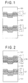
- FIG. 1 is a sectional view showing an information recording medium according to a first embodiment of the invention.
- the information recording medium is comprised of a substrate 101, a second information recording layer L2, a transparent layer 102, a first information recording layer L1, and a light transmissive layer 103.
- Information is recorded on the first and second information recording layers L1 and L2 independently of each other.
- the first information recording layer L1 is comprised of a second dielectric protective film 12, a phase change recording film 1, and a first dielectric protective film 11.
- the second information recording layer L2 is comprised of a reflector film 3, a second dielectric protective film 22, a phase change recording film 2, and a first dielectric protective film 21.
- the second information recording layer L2 may be recordable and also reproducible only, and that information signals are recorded/reproduced upon exposure of the light transmissive layer 103 to laser light.
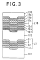
- FIG. 2 is a sectional view showing an information recording medium according to a second embodiment of the invention.
- the information recording medium is comprised of a substrate 101, a second information recording layer L2, a transparent layer 102, a first information recording layer L1A, and a light transmissive layer 103.
- the first information recording layer L1A is comprised of a fourth dielectric protective film 12c, a third dielectric protective film 12b, a second dielectric protective film 12a, a phase change recording film 1, and a first dielectric protective film 11.
- the second information recording layer L2 is comprised of a reflector film 3, a second dielectric protective film 22, a phase change recording film 2, and a first dielectric protective film 21.
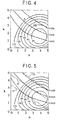
- FIG. 3 is a sectional view showing an information recording medium according to a third embodiment of the invention.
- the information recording medium is comprised of a substrate 101, a second information recording layer L2, a transparent layer 102, a first information recording layer L1B, and a light transmission layer 103.
- the first information recording layer L1B is comprised of a sixth dielectric protective film 12f, a fifth dielectric protective film 12e, a fourth dielectric protective film 12d, a phase change recording film 1, a third dielectric protective film 11c, a second dielectric protective film 11b, and a first dielectric protective film 11a.
- the second information recording layer L2 is comprised of a reflector film 3, a second dielectric protective film 22, a phase change recording film 2, and a first dielectric protective film 21.
- a fundamental solution to the above problem which the information recording media according to the first to third embodiments should find is to reduce the difference in transmissivity between the recorded and unrecorded portions of the first information recording layer L1 to make its influence on the recording/reproducing of information signals on/from the second information recording layer L2 negligible.
- the invention is featured in the film forming structure and material selection for preparing the first information recording layer L1 in order to suppress the difference in transmissivity between the recorded and unrecorded portions of the first information recording layer.
- the invention is not limited to the information recording media according to the first to third embodiments as to the number of dielectric protective films, etc.
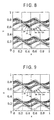
- FIGS. 4 and 5 show calculated reflectivities and transmissivities of the first information recording layer having a three-layered structure comprised of PC substrate/dielectric film/phase change recording film/dielectric film.
- the calculation is performed by appropriately selecting the thickness of each film and using the optical constants (n, k) of the phase change recording film as variables.
- the optical constants (n, k) so paired as to set the reflectivity to 2, 4, 6, 8, 10, and 12% are plotted as substantially concentric curves.
- the optical constants (n, k) so paired as to set the transmissivity T to 38, 50, and 64% are plotted as broken lines.
- the wavelength is 405 nm
- the thickness of the phase change recording film is 6 nm
- a recording medium be considered whose crystalline portion has a transmissivity of 50%, for example.
- the first information recording layer is required to maximize the difference in reflectivity between its crystalline and amorphous portions.
- R 1c the reflectivity of the unrecorded portion (the crystalline portion) of the first information recording layer L1 be in the order of 10% and that R 1a (the reflectivity of the recorded mark (the amorphous portion) of the first information recording layer L1) be minimized.
- R 1a 0%.
- R 1c is large, laser power required for recording is so large that practically no information can be recorded.
- the (transmissivity, reflectivity) of the crystalline portion at the point A and of the amorphous portion at the point B are (50%, 12%) and (46%, 4%), respectively.
- the transmissivities are within their tolerance, and the reflectivities are also sufficient.
- Aa is the ratio of the area occupied by the marks recorded on guide grooves such as grooves or lands
- these marks are recorded such that a recorded portion alternates with an unrecorded portion, and the area occupied by these marks does not exceed the area occupied by the unrecorded portions, and hence Aa ⁇ 0.5 is established.
- each recorded mark is too small, no signal can be produced therefrom, and thus, 0.2 ⁇ Aa should be satisfied.
- the transmissivity Tnr of the unrecorded portion and the transmissivity Tr of the recorded portion in the first information recording layer L1 satisfy 0.3 ⁇ Tnr ⁇ 0.8 0.3 ⁇ Tr ⁇ 0.8
- a reproduced signal from the second information recording layer L2 can be expressed as a value obtained by multiplying the square of the transmissivity of the first information recording layer L1 and the reflectivity of the second information recording layer L2 with the amount of incident light.
- the first information recording layer L1 has too small a transmissivity
- the level of signals reproduced from the second information recording layer L2 becomes too small and thus insufficient.
- the recording layer L1 has too large a transmissivity, the amount of light reflecting from itself and the light absorption coefficient during recording on itself are decreased to such a small extent that satisfactory reproduction and recording cannot be achieved. This is why any reproduced signal from the second information recording layer L2 must satisfy 0.3 ⁇ Tnr ⁇ 0.8 and 3 ⁇ Tr ⁇ 0.8.
- T 1a the transmissivity of the amorphous portion
- T 1c the transmissivity of the crystalline portion
- Aa the area occupied by the amorphous portions (recorded marks)
- T 1a -(1+K)+(1+K)Aa+ 1+K (1+K)Aa
- T 1a -(1+K)+(1+K)Aa- 1+K (1+K)Aa
- T 1c -(1+K)(1-Aa)- 1+K (1+K)Aa
- T 1c - 1+ 1+K (1-Aa) 1+K Aa T 1c
- T 1a 1- 1+K (1-Aa) 1+K Aa T 1c
- T 1a 1- 1-K (1-Aa) 1-K Aa T 1c are established.
- T 1a satisfying -0.15 ⁇ ⁇ Pr 2 ⁇ 0.15 is indicated as a zone interposed between the two straight lines (a) and (f)
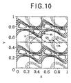
- FIGS. 8 to 10 show the relationship between the thickness and optical constants of the dielectric protective films.
- FIG. 8 which corresponds to the configuration according to the first embodiment shown in FIG. 1, shows the case where the thickness of the phase change recording film 1 is 6 nm.
- the X axis indicates the value obtained by dividing the thickness of the dielectric film 12 by ⁇ /n (where n is the optical constant of the film 12).
- the Y axis indicates the value obtained by dividing the thickness of the first dielectric film 11 by ⁇ /n (where n is the optical constant of the film 11).
- FIG. 9 which corresponds to the configuration according to the second embodiment shown in FIG. 2, shows the case where the thickness of the phase change recording film 1 is 6 nm.
- the X axis indicates the value obtained by dividing the thickness of the second dielectric film 12a by ⁇ /n (where n is the optical constant of the film 12a).
- the Y axis indicates the value obtained by dividing the thickness of the first dielectric film 11 by ⁇ /n (where n is the optical constant of the film 11).
- the thickness of the third dielectric film 12b is 104 nm (( ⁇ /n) ⁇ 4/8), and that of the fourth dielectric film 12c is 131 nm (( ⁇ /n) ⁇ 6/8).
- FIG. 10 which corresponds to the configuration according to the third embodiment shown in FIG. 3, shows the case where the thickness of the phase change recording film 1 is 6 nm.
- the X axis indicates the value obtained by dividing the thickness of the fourth dielectric film 12d by ⁇ /n (where n is the optical constant of the film 12d).
- the Y axis indicates the value obtained by dividing the thickness of the first dielectric film 11a by ⁇ /n (where n is the optical constant of the film 11a).
- the thickness of the second dielectric film 11b is 182 nm (( ⁇ /n) ⁇ 7/8), that of the third dielectric film 11c is 22 nm (( ⁇ /n) ⁇ 1/8), that of the fifth dielectric film 12e is 22 nm (( ⁇ /n) ⁇ 1/8), and that of the sixth dielectric film 12f is 153 nm (( ⁇ /n) ⁇ 7/8).
- a first protective layer (m/2 + 1/4) - 1/8 ⁇ ⁇ (di/( ⁇ /ni)) ⁇ (m/2 + 1/4) + 1/8 (where m is an integer, i is a natural number, di is the thickness of each protective film [nm], ni is the refractive index of each protective film [nm], and ⁇ is the wavelength of the laser light [nm]), and as to a second protective layer (k/2) - 1/8 ⁇ ⁇ (dj/( ⁇ /nj)) ⁇ (k/2) + 1/8 (where k is an integer, j is a natural number, dj is the thickness of each protective film [nm], nj is the refractive index of each protective film [nm], and ⁇ is the wavelength of the laser light [nm]).
- the reflector film 3, the second dielectric film 22, the phase change recording film 2, the first dielectric film 21 were sequentially vacuum deposited by sputtering onto the 0.6 mm thick substrate 101, and then a UV curable resin was spin coated.
- the first dielectric film 11, the phase change recording film 1, and the second dielectric film 12 were sequentially vacuum deposited by sputtering onto another 0.6 mm thick substrate for the light transmissive layer 103, and then the UV curable resin was spin coated.
- the entire surfaces of the phase change recording films 1 and 2 of the respective substrates were exposed to laser light to become crystalline, and the resulting substrates were then bonded together using the UV curable resin.
- the transparent layer 102 formed of the UV cured resin between the two information recording layers L1 and L2 is 40 ⁇ m thick.
- the first dielectric film 11 corresponds to the first protective layer, and the second dielectric film 12 to the second protective layer.
- the first dielectric film 11 of the first information recording layer L1 is made of ZnS ⁇ SiO 2 and is 220 nm thick. Its phase change recording film 1 is made of AgInSbTe and is 6 nm thick. Its second dielectric film 12 is made of ZnS ⁇ SiO 2 and is 260 nm thick.
- the first dielectric film 21 of the second information recording layer L2 is made of ZnS ⁇ SiO 2 and is 160 nm thick.
- Its phase change recording film 2 is made of AgInSbTe and is 14 nm thick.
- Its second dielectric film 22 is made of ZnS ⁇ SiO 2 and is 30 nm thick.
- Its reflector film 3 is made of Al and is 100 nm thick.
- the optical properties of the first and second information recording layers L1 and L2 are indicated below. It should be noted that the following reflectivities, light absorption coefficients, and light transmissivities are obtained on condition that the intensity of light entering the respective information recording layers is 100%. Thus, for the second information recording layer L2, the light has 100% intensity upon entrance into the layer L2 after having passed through the light transmissive layer and the first information recording layer.
- first information recording layer > Crystalline portion Reflectivity R 1c 11.2% Light absorption coefficient A 1c 36.1% Light transmissivity T 1c 52.6% Amorphous portion Reflectivity R 1a 1.7% Light absorption coefficient A 1a 48.2% Light transmissivity T 1a 50.1%
- second information recording layer > Crystalline portion Reflectivity R 1c 40.3% Amorphous portion Reflectivity R 1a 15.5%
- the transmissivity for light transmitting through the recorded portions (lands/grooves) of the first information recording layer is 51.3%, and that for light transmitting through the unrecorded portions is 52.6%.
- the rate of fluctuation of the light for recording on the second information recording layer L2 is 2.4% and for reproducing from the same layer L2 is 4.8%, provided that the light has transmitted through the recorded portion of the first information recording layer L1.
- Recording/reproducing experiments were carried out using a bluish purple laser beam having a wavelength of 405 nm, as to the information recording layers L1 and L2 of the information recording medium according to the first embodiment. Since the difference in transmissivity between the recorded and unrecorded portions of the first information recording layer L1 was small, the first embodiment allowed information signals to be recorded/reproduced satisfactorily also on/from the second information recording layer L2, independently of whether information is recorded or not on the first information recording layer L1.
- the reflector film 3, the second dielectric film 22, the phase change recording film 2, and the first dielectric film 21 were sequentially vacuum deposited by sputtering onto the 0.6 mm thick substrate 101, and then the UV curable resin was spin coated.
- the first dielectric film 11, the phase change recording film 1, the second dielectric film 12a, the third dielectric film 12b, and the fourth dielectric film 12c were sequentially vacuum deposited by sputtering onto another 0.6 mm thick substrate for the light transmissive layer 103, and then the UV curable resin was spin coated.
- the transparent layer 102 formed of the UV cured resin between the two information recording layers L1A and L2 was 40 ⁇ m thick.
- the first dielectric film 11 corresponds to the first protective layer, and a layer formed of the second to fourth dielectric films 12a to 12c corresponds to the second protective layer.
- the first dielectric film 11 of the first information recording layer L1A is made of ZnS ⁇ SiO 2 and is 230 nm thick.
- Its phase change recording film 1 is made of AgInSbTe and is 6 nm thick.
- Its second dielectric film 12a is made of ZnS ⁇ SiO 2 and is 20 nm thick.
- Its third dielectric film 12b is made of AlN and is 180 nm thick.
- Its fourth dielectric film 12c is made of ZnS ⁇ SiO 2 and is 90 nm thick.
- the first dielectric film 21 of the second information recording layer L2 is made of ZnS ⁇ SiO 2 and is 160 nm thick.
- Its phase change recording film 2 is made of AgInSbTe and is 14 nm thick.
- Its second dielectric film 22 is made of ZnS ⁇ SiO 2 and is 30 nm thick.
- Its reflector film 3 is made of Al and is 100 nm thick.
- the optical properties of the first and second information recording layers L1A and L2 are indicated below. It should be noted that the following reflectivities, light absorption coefficients, and light transmissivities are obtained on condition that the intensity of light entering the respective information recording layers is 100%. Thus, for the second information recording layer L2, the light has 100% intensity upon entrance into the layer L2 after having passed through the light transmissive layer and the first information recording layer L1A.
- first information recording layer > Crystalline portion Reflectivity R 1c 11.2% Light absorption coefficient A 1c 32.7% Light transmissivity T 1c 56.1% Amorphous portion Reflectivity R 1a 2.7% Light absorption coefficient A 1a 43.6% Light transmissivity T 1a 53.6% ⁇ Optical properties of second information recording layer> Crystalline portion Reflectivity R 1c 40.3% Amorphous portion Reflectivity R 1a 15.5%
- the transmissivity for light transmitting through the recorded portions (lands/grooves) of the first information recording layer is 54.9%, and that for light transmitting through its unrecorded portions is 56.1%.
- the rate of fluctuation of the light for recording on the second information recording layer L2 is 2.2% and for reproducing from the same layer L2 is 4.5%, provided that the light has transmitted through the recorded portion of the first information recording layer L1A.
- the reflector film 3, the second dielectric film 22, the phase change recording film 2, and the first dielectric film 21 were sequentially vacuum deposited by sputtering onto the 0.6 mm thick substrate 101, and then the UV curable resin was spin coated.
- the first dielectric film 11a, the second dielectric film 11b, the third dielectric film 11c, the phase change recording film 1, the fourth dielectric film 12d, the fifth dielectric film 12e, and the sixth dielectric film 12f were sequentially vacuum deposited by sputtering onto another 0.6 mm thick substrate for the light transmissive layer 103, and then the UV curable resin was spin coated.
- the transparent layer 102 formed of the UV cured resin between the two information recording layers L1B and L2 is 40 ⁇ m thick.
- a layer formed of the first to third dielectric films 11a to 11c corresponds to the first protective layer, and a layer formed of the fourth to sixth dielectric films 12d to 12f corresponds to the second protective layer.
- the first dielectric film 11a of the first information recording layer L1B is made of ZnS ⁇ SiO 2 and is 90 nm thick. Its second dielectric film 11b is made of AlN and is 110 nm thick. Its third dielectric film 11c is made of ZnS ⁇ SiO 2 and is 90 nm thick. Its phase change recording film 1 is made of AgInSbTe and is 6 nm thick. Its fourth dielectric film 12d is made of ZnS ⁇ SiO 2 and is 40 nm thick. Its fifth dielectric film 12e is made of AlN and is 100 nm thick. Its sixth dielectric film 12f is made of ZnS ⁇ SiO 2 and is 50 nm thick.
- the first dielectric film 21 of the second information recording layer L2 is made of ZnS ⁇ SiO 2 and is 160 nm thick.
- Its phase change recording film 2 is made of AgInSbTe and is 14 nm thick.
- Its second dielectric film 22 is made of ZnS ⁇ SiO 2 and is 30 nm thick.
- Its reflector film 3 is made of Al and is 100 nm thick.
- the optical constant of the dielectric film ZnS ⁇ SiO 2 is 2.3 and that of AlN is 1.95
- the previously mentioned condition is also satisfied.
- the optical properties of the first and second information recording layers L1B and L2 are indicated below. It should be noted that the following reflectivities, light absorption coefficients, and light transmissivities are obtained on condition that the intensity of light entering the respective information recording layers is 100%. Thus, for the second information recording layer L2, the light has 100% intensity upon entrance into the layer L2 after having passed through the light transmissive layer and the first information recording layer L1B.
- first information recording layer > Crystalline portion Reflectivity R 1c 11.3% Light absorption coefficient A 1c 36.1% Light transmissivity T 1c 52.6% Amorphous portion Reflectivity R 1a 1.8% Light absorption coefficient A 1a 48.0% Light transmissivity T 1a 50.2%
- second information recording layer > Crystalline portion Reflectivity R 1c 40.3% Amorphous portion Reflectivity R 1a 15.5%
- the transmissivity for light transmitting through the recorded portions (lands/grooves) of the first information recording layer is 51.4%
- that for light transmitting through its unrecorded portions is 52.6%.
- the rate of fluctuation of the light for recording on the second information recording layer L2 is 2.4% and for reproducing from the same layer L2 is 4.8%, provided that the light has transmitted through the recorded section of the first information recording layer L1B.
- phase change recording film satisfying R c2 > R a2 used for the second information recording layer in each of the above embodiments a so-called reversible phase change recording film satisfying R c2 ⁇ R a2 may be used.
- the second information recording layer may be reproducible only (ROM) and magneto-optic. There is no limitation as to how information signals are recorded/reproduced on/from the second information recording layer.
Landscapes
- Optical Recording Or Reproduction (AREA)
- Optical Record Carriers And Manufacture Thereof (AREA)
Abstract
Description
[Eq. 1]
Transmissivity of recorded portion of layer L1:
[Eq. 12]
[Eq. 13]
[Eq. 14]
As to a first protective layer
| <Optical properties of first information recording layer> | |
| Crystalline portion | |
| Reflectivity R1c | 11.2% |
| Light absorption coefficient A1c | 36.1% |
| Light transmissivity T1c | 52.6% |
| Amorphous portion | |
| Reflectivity R1a | 1.7% |
| Light absorption coefficient A1a | 48.2% |
| Light transmissivity T1a | 50.1% |
| <Optical properties of second information recording layer> | |
| Crystalline portion | |
| Reflectivity R1c | 40.3% |
| Amorphous portion | |
| Reflectivity R1a | 15.5% |
| <Optical properties of first information recording layer> | |
| Crystalline portion | |
| Reflectivity R1c | 11.2% |
| Light absorption coefficient A1c | 32.7% |
| Light transmissivity T1c | 56.1% |
| Amorphous portion | |
| Reflectivity R1a | 2.7% |
| Light absorption coefficient A1a | 43.6% |
| Light transmissivity T1a | 53.6% |
| <Optical properties of second information recording layer> | |
| Crystalline portion | |
| Reflectivity R1c | 40.3% |
| Amorphous portion | |
| Reflectivity R1a | 15.5% |
| <Optical properties of first information recording layer> | |
| Crystalline portion | |
| Reflectivity R1c | 11.3% |
| Light absorption coefficient A1c | 36.1% |
| Light transmissivity T1c | 52.6% |
| Amorphous portion | |
| Reflectivity R1a | 1.8% |
| Light absorption coefficient A1a | 48.0% |
| Light transmissivity T1a | 50.2% |
| <Optical properties of second information recording layer> | |
| Crystalline portion | |
| Reflectivity R1c | 40.3% |
| Amorphous portion | |
| Reflectivity R1a | 15.5% |
Claims (6)
- An information recording medium having a light transmissive layer (103), a first information recording layer (L1), a transparent layer (102), and a second information recording layer (L2) sequentially stacked to reproduce information signals upon exposure of said light transmissive layer (103) to laser light, characterized in that
said first information recording layer (L1) comprises a first protective layer (11), a phase change recording film (1), and a second protective layer (12) sequentially from said light transmissive layer (103), and
the rate of power fluctuation between a reproducing light passing through a recorded region of said first information recording layer (L1) and that passing through an unrecorded region of said first information recording layer (L1), during reproduction of the information signals from said second information recording layer (L2), are within 10%. - The information recording medium according to claim 1, wherein
assuming that a percentage of an area occupied by recorded marks in the recorded region of said first information recording layer (L1) is Aa, then - The information recording medium according to claim 1 or 2, wherein
assuming that a transmissivity of the recorded region of said first information recording layer (L1) is Tr, then
assuming that a transmissivity of the unrecorded region of said first information recording layer (L1) is Tnr, then - The information recording medium according to any one of claims 1 to 3, said medium having a light transmissive layer (103), a first information recording layer (L1), a transparent layer (102), and a second information recording layer (L2) sequentially stacked to reproduce information signals upon exposure of said light transmissive layer (103) to laser light, wherein
said first information recording layer (L1) comprises a first protective layer (11), a phase change recording film (1), and a second protective layer (12) sequentially from said light transmissive layer (103), and
assuming that a refractive index and an extinction coefficient of a crystalline portion of said phase change recording film (1) are n1c and k1c, respectively, and that a refractive index and an extinction coefficient of an amorphous portion of said phase change recording film (1) are n1a and k1a, respectively, then - The information recording medium according to any one of claims 1 to 3, said medium having a light transmissive layer (103), a first information recording layer (L1), a transparent layer (102), and a second information recording layer (L2) sequentially stacked to reproduce information signals upon exposure of said light transmissive layer (103) to laser light, wherein
said first information recording layer (L1) comprises a first protective layer (11), a phase change recording film (1), and a second protective layer (12) sequentially from said light transmissive layer (103), and
assuming that a number of protective films constituting said first protective layer (11) is I, a thickness of each of said protective films is di [nm] (where i is a natural number), a refractive index of each of said protective films is ni, a wavelength of the laser light is λ [nm], and m is an integer, then a sum Σ for all i running from 1 to I is given substantially as
assuming that a number of protective films constituting said second protective layer (12) is J, a thickness of each of said protective films is dj [nm] (where j is a natural number), a refractive index of each of said protective films is nj, and k is an integer, then a sum Σ for all j running from 1 to J is given substantially as - The information recording medium according to any one of claims 1 to 3, said medium having a light transmissive layer (103), a first information recording layer (L1), a transparent layer (102), and a second information recording layer (L2) sequentially stacked to reproduce information signals upon exposure of said light transmissive layer (103) to laser light, wherein
said first information recording layer (L1) comprises a first protective layer (11), a phase change recording film (1), and a second protective layer (12) sequentially from said light transmissive layer, and
assuming that a number of protective films constituting said first protective layer (11) is I, a thickness of each of said protective films is di [nm] (where i is a natural number), a refractive index of each of said protective films is ni, a wavelength of the laser light is λ [nm], and m is an integer, then a sum Σ for all i running from 1 to I is given substantially as
assuming that a number of protective films constituting said second protective layer (12) is J, a thickness of each of said protective films is dj [nm] (where j is a natural number), a refractive index of each of said protective films is nj, and k is an integer, then a sum Σ for all j running from 1 to J is given substantially as
assuming that a refractive index and an extinction coefficient of a crystalline portion of said phase change recording film (1) are n1c and k1c, respectively, and that a refractive index and an extinction coefficient of an amorphous portion of said phase change recording film (1) are n1a and k1a, respectively, then
Applications Claiming Priority (2)
| Application Number | Priority Date | Filing Date | Title |
|---|---|---|---|
| JP2001023195 | 2001-01-31 | ||
| JP2001023195A JP2002230828A (en) | 2001-01-31 | 2001-01-31 | Information recording medium |
Publications (2)
| Publication Number | Publication Date |
|---|---|
| EP1229528A2 true EP1229528A2 (en) | 2002-08-07 |
| EP1229528A3 EP1229528A3 (en) | 2005-07-13 |
Family
ID=18888508
Family Applications (1)
| Application Number | Title | Priority Date | Filing Date |
|---|---|---|---|
| EP02001938A Withdrawn EP1229528A3 (en) | 2001-01-31 | 2002-01-31 | Information recording medium |
Country Status (3)
| Country | Link |
|---|---|
| US (1) | US6724716B2 (en) |
| EP (1) | EP1229528A3 (en) |
| JP (1) | JP2002230828A (en) |
Cited By (5)
| Publication number | Priority date | Publication date | Assignee | Title |
|---|---|---|---|---|
| EP1302934A3 (en) * | 2001-10-12 | 2003-08-13 | Matsushita Electric Industrial Co., Ltd. | Optical information recording medium, its measuring method and optical information recording/reproducing method |
| EP1496509A3 (en) * | 2003-07-10 | 2005-03-16 | Ricoh Company, Ltd. | Optical recording medium and production thereof |
| EP1580740A1 (en) * | 2004-03-19 | 2005-09-28 | Ricoh Company | Optical information recording medium |
| EP1542217A4 (en) * | 2002-09-18 | 2008-04-09 | Matsushita Electric Industrial Co Ltd | OPTICAL INFORMATION RECORDING MEDIUM AND METHOD OF MANUFACTURING |
| US9412407B2 (en) | 2002-08-29 | 2016-08-09 | Koninklijke Philips N.V. | Multi-stack optical storage medium |
Families Citing this family (10)
| Publication number | Priority date | Publication date | Assignee | Title |
|---|---|---|---|---|
| JP2003173573A (en) | 2001-12-07 | 2003-06-20 | Toshiba Corp | Optical information recording medium and optical disk drive |
| CA2489597A1 (en) * | 2002-06-18 | 2003-12-24 | Koninklijke Philips Electronics N.V. | Optical data storage medium |
| KR101049985B1 (en) * | 2003-08-07 | 2011-07-19 | 파나소닉 주식회사 | Optical information recording medium, its manufacturing method, manufacturing apparatus, recording / reproducing method, and recording / reproducing apparatus |
| JP2005100526A (en) * | 2003-09-25 | 2005-04-14 | Hitachi Ltd | Device manufacturing method and observation method |
| JP4313648B2 (en) * | 2003-11-05 | 2009-08-12 | Tdk株式会社 | Optical recording medium and manufacturing method thereof |
| JP2005209247A (en) * | 2004-01-20 | 2005-08-04 | Tdk Corp | Optical recording medium |
| EP2230665B1 (en) * | 2004-07-12 | 2011-11-02 | Panasonic Corporation | Method of producing an information recording medium and information recording/reproducing method |
| EP1714757B1 (en) * | 2005-04-21 | 2008-09-10 | Rohm and Haas Company | Wood preservatives |
| JP4285451B2 (en) * | 2005-07-06 | 2009-06-24 | 株式会社日立製作所 | Information recording medium, information reproducing method and information recording method |
| JP2008097802A (en) * | 2006-09-15 | 2008-04-24 | Tdk Corp | Multilayer optical recording medium and recording method on multilayer optical recording medium |
Family Cites Families (10)
| Publication number | Priority date | Publication date | Assignee | Title |
|---|---|---|---|---|
| US5424106A (en) * | 1992-04-17 | 1995-06-13 | Matsushita Electric Industrial Co., Ltd. | Optical information recording medium and method of designing its structure |
| US5958649A (en) * | 1995-03-27 | 1999-09-28 | Hitachi, Ltd. | Information recording medium and information memory apparatus |
| US5764619A (en) * | 1995-04-07 | 1998-06-09 | Matsushita Electric Industrial Co., Ltd. | Optical recording medium having two separate recording layers |
| TW414892B (en) * | 1996-05-28 | 2000-12-11 | Ibm | Optical data storage system with multiple rewriteable phase-change recording layers |
| JPH11195243A (en) * | 1997-12-26 | 1999-07-21 | Sony Corp | Multilayer optical disc and recording / reproducing device |
| JPH11203725A (en) * | 1998-01-16 | 1999-07-30 | Nec Corp | Phase transition optical disk |
| JPH11250502A (en) * | 1998-02-26 | 1999-09-17 | Sony Corp | optical disk |
| EP0957477A3 (en) | 1998-05-15 | 2003-11-05 | Matsushita Electric Industrial Co., Ltd. | Optical information recording medium, recording and reproducing method therefor and optical information recording and reproduction apparatus |
| JP2000235732A (en) * | 1999-02-12 | 2000-08-29 | Sony Corp | Multilayer optical disc |
| JP2000322770A (en) * | 1999-05-12 | 2000-11-24 | Matsushita Electric Ind Co Ltd | Optical information recording medium |
-
2001
- 2001-01-31 JP JP2001023195A patent/JP2002230828A/en not_active Withdrawn
-
2002
- 2002-01-31 EP EP02001938A patent/EP1229528A3/en not_active Withdrawn
- 2002-01-31 US US10/059,129 patent/US6724716B2/en not_active Expired - Fee Related
Cited By (8)
| Publication number | Priority date | Publication date | Assignee | Title |
|---|---|---|---|---|
| EP1302934A3 (en) * | 2001-10-12 | 2003-08-13 | Matsushita Electric Industrial Co., Ltd. | Optical information recording medium, its measuring method and optical information recording/reproducing method |
| US6893698B2 (en) | 2001-10-12 | 2005-05-17 | Matsushita Electric Industrial Co., Ltd. | Optical information recording medium, optical measuring method and optical information recording/reproducing method |
| US9412407B2 (en) | 2002-08-29 | 2016-08-09 | Koninklijke Philips N.V. | Multi-stack optical storage medium |
| EP1542217A4 (en) * | 2002-09-18 | 2008-04-09 | Matsushita Electric Industrial Co Ltd | OPTICAL INFORMATION RECORDING MEDIUM AND METHOD OF MANUFACTURING |
| EP1496509A3 (en) * | 2003-07-10 | 2005-03-16 | Ricoh Company, Ltd. | Optical recording medium and production thereof |
| EP1580740A1 (en) * | 2004-03-19 | 2005-09-28 | Ricoh Company | Optical information recording medium |
| US7095706B2 (en) | 2004-03-19 | 2006-08-22 | Ricoh Company, Ltd. | Optical information recording medium |
| US7251212B2 (en) | 2004-03-19 | 2007-07-31 | Ricoh Company, Ltd. | Optical information recording medium |
Also Published As
| Publication number | Publication date |
|---|---|
| JP2002230828A (en) | 2002-08-16 |
| EP1229528A3 (en) | 2005-07-13 |
| US6724716B2 (en) | 2004-04-20 |
| US20020146875A1 (en) | 2002-10-10 |
Similar Documents
| Publication | Publication Date | Title |
|---|---|---|
| US5485452A (en) | Optical information recording medium | |
| KR100776850B1 (en) | Optical recording medium and optical recording and reproducing apparatus | |
| EP1229528A2 (en) | Information recording medium | |
| KR20000029042A (en) | optical recording medium and optical recording/reproducing apparatus | |
| US6240060B1 (en) | Phase change optical recording medium | |
| EP1500094B1 (en) | Dual stack optical data storage medium | |
| KR100731472B1 (en) | Optical record reproducing method and optical recording medium | |
| KR100385980B1 (en) | High density optical recording medium and method for recording data on the same | |
| EP1184858A2 (en) | Optical information recording medium and method for optical recording, reproducing and erasing information | |
| US6657946B2 (en) | Phase change type optical disk having different reflectances at crystalline and amorphous states | |
| JPH09237441A (en) | Optical disc and recording / reproducing method thereof | |
| JPH11120613A (en) | Optical recording medium | |
| US7566523B2 (en) | Optical information-recording media and optical information-recording/reproduction apparatus | |
| KR19990023532A (en) | Phase change optical disc media | |
| EP0762408B1 (en) | Multi-layer optical disk | |
| KR20010010401A (en) | Phase change optical medium | |
| US20100002559A1 (en) | Compatible optical recording medium | |
| JP3539000B2 (en) | Multilayer optical disc | |
| KR20060032992A (en) | Multilayer Optical Data Storage Media and Uses of It | |
| US7420908B2 (en) | Optical recording medium | |
| JP2001189033A (en) | Optical recording medium | |
| KR20050012252A (en) | Optical data storage medium and use of such medium | |
| EP1501086A1 (en) | Method and apparatus for recording/reproducing optical information | |
| US8693302B2 (en) | Compatible optical recording medium | |
| JPH03241538A (en) | Optical recording medium disk |
Legal Events
| Date | Code | Title | Description |
|---|---|---|---|
| PUAI | Public reference made under article 153(3) epc to a published international application that has entered the european phase |
Free format text: ORIGINAL CODE: 0009012 |
|
| AK | Designated contracting states |
Kind code of ref document: A2 Designated state(s): AT BE CH CY DE DK ES FI FR GB GR IE IT LI LU MC NL PT SE TR |
|
| AX | Request for extension of the european patent |
Free format text: AL;LT;LV;MK;RO;SI |
|
| PUAL | Search report despatched |
Free format text: ORIGINAL CODE: 0009013 |
|
| AK | Designated contracting states |
Kind code of ref document: A3 Designated state(s): AT BE CH CY DE DK ES FI FR GB GR IE IT LI LU MC NL PT SE TR |
|
| AX | Request for extension of the european patent |
Extension state: AL LT LV MK RO SI |
|
| 17P | Request for examination filed |
Effective date: 20050801 |
|
| AKX | Designation fees paid |
Designated state(s): AT BE CH CY DE DK ES FI FR GB GR IE IT LI LU MC NL PT SE TR |
|
| STAA | Information on the status of an ep patent application or granted ep patent |
Free format text: STATUS: THE APPLICATION IS DEEMED TO BE WITHDRAWN |
|
| 18D | Application deemed to be withdrawn |
Effective date: 20060902 |