EP1229706A2 - System und Verfahren zum schalten von digitalen Teilnehmerleitungsdiensten - Google Patents
System und Verfahren zum schalten von digitalen Teilnehmerleitungsdiensten Download PDFInfo
- Publication number
- EP1229706A2 EP1229706A2 EP01850146A EP01850146A EP1229706A2 EP 1229706 A2 EP1229706 A2 EP 1229706A2 EP 01850146 A EP01850146 A EP 01850146A EP 01850146 A EP01850146 A EP 01850146A EP 1229706 A2 EP1229706 A2 EP 1229706A2
- Authority
- EP
- European Patent Office
- Prior art keywords
- subscriber
- data processing
- processing equipment
- digital
- cross
- Prior art date
- Legal status (The legal status is an assumption and is not a legal conclusion. Google has not performed a legal analysis and makes no representation as to the accuracy of the status listed.)
- Withdrawn
Links
Images








Classifications
-
- H—ELECTRICITY
- H04—ELECTRIC COMMUNICATION TECHNIQUE
- H04L—TRANSMISSION OF DIGITAL INFORMATION, e.g. TELEGRAPHIC COMMUNICATION
- H04L12/00—Data switching networks
- H04L12/28—Data switching networks characterised by path configuration, e.g. LAN [Local Area Networks] or WAN [Wide Area Networks]
- H04L12/2854—Wide area networks, e.g. public data networks
- H04L12/2856—Access arrangements, e.g. Internet access
- H04L12/2869—Operational details of access network equipments
- H04L12/2878—Access multiplexer, e.g. DSLAM
-
- H—ELECTRICITY
- H04—ELECTRIC COMMUNICATION TECHNIQUE
- H04M—TELEPHONIC COMMUNICATION
- H04M3/00—Automatic or semi-automatic exchanges
- H04M3/22—Arrangements for supervision, monitoring or testing
- H04M3/26—Arrangements for supervision, monitoring or testing with means for applying test signals or for measuring
- H04M3/28—Automatic routine testing ; Fault testing; Installation testing; Test methods, test equipment or test arrangements therefor
- H04M3/30—Automatic routine testing ; Fault testing; Installation testing; Test methods, test equipment or test arrangements therefor for subscriber's lines, for the local loop
-
- H—ELECTRICITY
- H04—ELECTRIC COMMUNICATION TECHNIQUE
- H04Q—SELECTING
- H04Q1/00—Details of selecting apparatus or arrangements
- H04Q1/02—Constructional details
- H04Q1/14—Distribution frames
- H04Q1/145—Distribution frames with switches arranged in a matrix configuration
-
- H—ELECTRICITY
- H04—ELECTRIC COMMUNICATION TECHNIQUE
- H04Q—SELECTING
- H04Q1/00—Details of selecting apparatus or arrangements
- H04Q1/02—Constructional details
- H04Q1/14—Distribution frames
- H04Q1/147—Distribution frames using robots for distributing
-
- H—ELECTRICITY
- H04—ELECTRIC COMMUNICATION TECHNIQUE
- H04M—TELEPHONIC COMMUNICATION
- H04M3/00—Automatic or semi-automatic exchanges
- H04M3/08—Indicating faults in circuits or apparatus
- H04M3/12—Marking faulty circuits "busy"; Enabling equipment to disengage itself from faulty circuits ; Using redundant circuits; Response of a circuit, apparatus or system to an error
-
- H—ELECTRICITY
- H04—ELECTRIC COMMUNICATION TECHNIQUE
- H04Q—SELECTING
- H04Q2213/00—Indexing scheme relating to selecting arrangements in general and for multiplex systems
- H04Q2213/13039—Asymmetrical two-way transmission, e.g. ADSL, HDSL
-
- H—ELECTRICITY
- H04—ELECTRIC COMMUNICATION TECHNIQUE
- H04Q—SELECTING
- H04Q2213/00—Indexing scheme relating to selecting arrangements in general and for multiplex systems
- H04Q2213/13076—Distributing frame, MDF, cross-connect switch
Definitions
- the present invention relates to a system and method for switching digital subscriber line service in which new connections are switched in and obsolete connections are switched out.
- MTAC metallic test access cross-connect
- DSL digital subscriber line
- xDSL digital subscriber line
- xDSL competitive local exchange carriers
- MTAC metallic test access cross-connect
- the MTAC also known as an exception switch, is used to allow test equipment to access the copper pairs coming in from the local loop, which connect customer equipment with the central office.
- the MTAC sits between the CLEC's DSL access multiplexer (DSLAM) and the local loop.
- DSL access multiplexer DSL access multiplexer
- some MTACs support limited fallback switching, allowing a subscriber to be switched over from a faulty DSL port to an operating one.
- the number of ports that support this feature are usually limited to a small percent of the total number of lines supported by the switch, and because of this, this switch requires regular cabling update visits.
- the ILEC provides a dedicated copper pair 102 from the subscriber's premises 104 to the CLEC's demarcation point 106 in the co-location arrangement (COLLO) at the CLEC's central office.
- the line is terminated first at the MDF 106 in the central office and then patched to a termination block 111 in the collocation (COLLO), through the test access unit 110, connecting the subscriber to the DSLAM 108 and enabling the CLEC to provide DSL service to the subscriber.
- the CLEC may want it disconnected, so that the DSL port can be connected to a new subscriber.
- the DSLAM port remains idle and not producing revenue.
- the ILEC can take up to 45-90 days to disconnect the line from the moment the CLEC makes the request.
- the CLEC is stuck with an idle DSLAM port. In order to free up the port, the CLEC would have to send a technician to the collocation (COLLO) to make the re-connection manually.
- test-access switches such as test-access switch 110
- test-access switch 110 which are being deployed between the DSLAM and the MDF have limited cross-connect capability and will not allow the obsolete subscriber line to be disconnected remotely.
- CLECs have resorted to Band-Aid solutions, such as investing in excess DSLAM capacity to offset the lost ports until the line is disconnected by the ILEC. The source of the problem however remains unsolved.
- the CLEC is using a test-access switch with limited cross-connect capability.
- the limited cross-connect capability allows only a small portion of the DSLAM access ports to be switched to another line. This only partially addresses the problem because statistically speaking the idle DSLAM port is likely to be connected to a line that cannot be switched remotely.
- the present invention is a system and method for providing digital subscriber line service that overcomes the problem of the prior art by using a true remote "any-to-any" cross-connect matrix switch to switch in new connections and switch out obsolete connections.
- the present invention alleviates the problem while preserving the essential test-access capability for local loop qualification and troubleshooting.
- the method of the present invention comprises the steps of: providing digital subscriber line service for a first subscriber via a cross-connect switch connected to a digital subscriber line access multiplexer connected to a digital telecommunications network, the cross connect switch supplying a connection between data processing equipment of the first subscriber and the digital subscriber line access multiplexer; receiving, at a network management system connected to the cross connect switch, an indication that the first subscriber has terminated service; in response to receiving the message at the network management system, transmitting a command to the cross connect switch to switch out the connection of the data processing equipment of first subscriber to the digital access multiplexer; and in response to receiving the command at the cross-connect switch, switching out the connection of the data processing equipment of first subscriber to the digital access multiplexer.
- the connection between data processing equipment of the first subscriber and the digital subscriber line access multiplexer may comprise a central office MDF connected to the data processing equipment of the first subscriber, a collocation arrangement demarcation connected to the cross-connect switch and a patch line connecting the central office MDF to the collocation arrangement demarcation.
- the connection between the data processing equipment of the first subscriber and the central office MDF may be unshared.
- the cross-connect switch may be connected to a port of the digital subscriber line access multiplexer. The step of switching out the connection of the data processing equipment of the first subscriber to the digital access multiplexer may free up the port of the digital subscriber line access multiplexer.
- the method may further comprise the steps of: receiving, at a network management system connected to the cross connect switch, an indication that a second subscriber has initiated service; in response to receiving the message at the network management system, transmitting a command to the cross connect switch to connect data processing equipment of second subscriber to the digital access multiplexer; and in response to receiving the command at the cross-connect switch, connecting the data processing equipment of the second subscriber to the digital access multiplexer.
- the cross-connect switch may be connected to a port of the digital subscriber line access multiplexer and the step of switching out the connection of the data processing equipment of first subscriber to the digital access multiplexer frees up the port of the digital subscriber line access multiplexer.
- the step of connecting the data processing equipment of the second subscriber to the digital access multiplexer may comprise the step of: connecting the data processing equipment of the second subscriber to the port of the digital subscriber line access multiplexer that was freed up by the step of switching out the connection of the data processing equipment of the first subscriber to the digital access multiplexer.
- the connection between data processing equipment of the first subscriber and the digital subscriber line access multiplexer may comprise a central office MDF connected to the data processing equipment of the first subscriber, a collocation arrangement demarcation connected to the cross-connect switch and a patch line connecting the central office MDF to the collocation arrangement demarcation.
- the connection between the data processing equipment of the first subscriber and the central office MDF may be unshared.
- the connection between data processing equipment of the second subscriber and the digital subscriber line access multiplexer may comprise a central office MDF connected to the data processing equipment of the second subscriber, a collocation arrangement demarcation connected to the cross-connect switch and a patch line connecting the central office MDF to the collocation arrangement demarcation.
- the connection between the data processing equipment of the second subscriber and the central office MDF may be unshared.
- Digital Subscriber Line is one of the signal protocols being used to carry broadband digital data over existing two-wire telephone lines.
- DSL Digital Subscriber Line
- Asymmetric DSL provides greater bandwidth for downstream data than for upstream data.
- ADSL reserves a portion of the available channel bandwidth for support of traditional analog telephone service (Plain Old Telephone Service (POTS)).
- POTS Personal Old Telephone Service
- ADSL is aimed primarily at the residential market.
- Another version of DSL is Symmetric DSL (SDSL). SDSL provides equal bandwidth in both the upstream and downstream directions and does not provide support for POTS. SDSL is better suited to business applications, such as network server communications, etc.
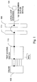
- Fig. 2 The arrangement by which the present invention switches, connects, and disconnects circuits is shown in Fig. 2.
- Fig. 2 there are a plurality of subscribers, such as subscribers 202 and 204, connected via two-wire telephone lines, such as lines 206 and 208, respectively.
- Blocks 202 and 204 include data processing equipment operated by the respective subscribers, as well as digital subscriber line interface equipment connected to the data processing equipment.
- Lines 206 and 208 are typically unshared, that is, they are not shared with other subscribers or with other services, such as analog voice telephony. Note however that if these line are shared with voice services, then splitters would be used both at the subscriber side and at the CO.
- Lines 206 and 208 are terminated at the MDF 210 in the central office and then connected via patch cables 212 and 214, respectively, to a termination block 216 in the collocation arrangement (COLLO).
- COLLO collocation arrangement
- Lines 218 and 220 connect from termination block to ports of cross-connect switch 222. Ports of cross connect switch 222 also connect to DSLAM 224.
- DSLAM 224 is a system that links customer DSL connections to an IP network. Typically, the IP network is the Internet, but may be any public or private data transport network.
- Network management system (NMS) 226 is connected to cross-connect switch 222 via a network 228, which can be any standard or proprietary network, such as a local area network (LAN) or a wide area network (WAN). NMS 226 can control the configuration and operation of cross-connect switch 222 over network 228. Likewise, NMS 226 can determine the status and configuration of cross-connect switch 222 over network 228. Note that serial connection based systems such as dial-up modems may also be used to establish control links to the cross-connect 222.
- cross-connect switch 22 An example of a suitable cross-connect switch 22, is the CONTROLPOINT TM switch available from NHC.
- the terms cross-connect and cross-connect switch are intended to mean any switch capable of reliably interconnecting telecommunications signals, including voice and data signals, from inputs to outputs under the influence of internal or external control signals. The terms are intended to encompass any such switch and control systems, including loop management systems.
- the CONTROLPOINT switch available from NHC is hereafter briefly described.
- the CONTROLPOINT solution is NHC's integrated non-blocking copper cross-connect system that helps CLECs and ILECs qualify and provision DSL and other services remotely without the need to enter the CLEC's COLLO or ILEC's CO.
- the CONTROLPOINT solution works with third party equipment such as Harris, Hekimian and Tollgrade Remote Test Units, enabling the cross-connect to be used as a test access platform for rapid loop qualification.
- the CONTROLPOINT solution may be deployed for DSL test access for local loop qualification, provisioning, migration and fallback switching.
- the CONTROLPOINT solution is intended to work with every major DSLAM vendor.
- the CONTROLPOINT cross-connect hardware has a matrix size and loopback capabilities that allow multiple services to be provisioned and migrated remotely on-the-fly and on-demand, thereby minimizing truck-rolls needed to qualify and provision high speed data services.
- the CONTROLPOINT solution allows the service provider to migrate users to higher speed data services quickly.
- the CLEC has the ability to use any available port on the DSLAM for fallback switching thus providing added value to both the CLEC and the subscriber.
- CONTROLPOINT CMS 226 is the control and management software for NHC's CONTROLPOINT Solution. Element 226 is later referred to generically as network management systems (NMS) and may also be referred to as terminals.
- NMS network management systems
- CONTROLPOINT CMS 226 communicate with NHC's CONTROLPOINT Copper Cross-Connect 222 via the CONTROLPOINT CMS Remote Controller to allow voice and high-speed data service providers to take full control of their copper cross-connect infrastructure.
- CONTROLPOINT CMS controls and tracks the physical connections within the CONTROLPOINT matrix, along with vital subscriber and equipment information.
- CONTROLPOINT CMS features an intuitive Graphical User Interface (GUI) for greater ease of use. Port connections involve a simple drag & drop operation.
- GUI Graphical User Interface
- Port connections involve a simple drag & drop operation.
- CONTROLPOINT CMS's integrated database tracks CONTROLPOINT subscriber/service connections and organizes the network into multi-level geographical views by country, city and site location.
- CONTROLPOINT CMS Remote is the SNMP control interface for NHC's CONTROLPOINT copper cross-connect switch, which allow the CONTROLPOINT cross-connect 222 to be managed via NHC's CONTROLPOINT Control and Management Software (CMS) or managed via third party Network Management System (NMS).
- CMS CONTROLPOINT Control and Management Software
- NMS third party Network Management System
- the CONTROLPOINT CMS Remote is connected to an Ethernet LAN and is accessible via standard SNMP commands.
- the CONTROLPOINT CMS Remote connects to CONTROLPOINT cross-connect via serial link.
- the device receives standard SNMP commands from the NMS or CONTROLPOINT CMS and communicates them to the CONTROLPOINT cross-connect.
- Support for API (application interfaces) within the CONTROLPOINT CMS Remote and CONTROLPOINT CMS allows for customization to support NHC's proposed line-sharing solution.
- cross-connect switch 222 and its controllers are hereafter referred to generically. Also, the terms cross-connect switch and cross-connect are used interchangeably.
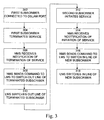
- FIG. 3 A process of operation of the present invention, implemented in the system shown in Fig. 2, is shown in Fig. 3. It is best viewed in conjunction with Fig. 2.
- the process begins with step 302, in which, initially, a first subscriber 202 is connected to cross-connect switch 222 via line 206, central office MDF 210, patch line 212, COLLO demarcation 216 and line 218.
- Cross-connect switch 222 connects subscriber 202 to port 232 of DSLAM 224 by way of connection 230.
- subscriber 202 terminates xDSL service with the operator of DSLAM 224, making the connection of subscriber 202 to port 232 of DSLAM 224 obsolete.
- network management system 226 receives notification of termination of service of subscriber 202.
- network management system 226 in response to receiving notification of termination of service of subscriber 202, transmits a command to cross-connect switch 222 to switch out the line of terminated subscriber 202.
- cross-connect switch 222 in response to the command received from network management system 226, switches out the line of terminated subscriber 202.
- cross connect switch 222 disconnects or deletes connection 230, which had been connecting the line from subscriber 202 to port 232 of DSLAM 224. The switch out frees up port 232 of DSLAM for future connection.
- a second subscriber 204 establishes new xDSL service with the operator of DSLAM 224.
- subscriber 204 is connected via line 208, central office MDF 210, patch line 214, and COLLO demarcation 216, through line 220, to cross-connect switch 222.
- network management system 226 receives notification of establishment of service of subscriber 204.
- network management system 226 transmits a command to cross-connect switch 222 to switch in the line of new subscriber 204.
- cross-connect switch 222 switches in the line of new subscriber 204.
- cross connect switch 222 establishes connection 234, which connects the line from subscriber 204 to a port of DSLAM 224, such as port 232, which was freed up by the disconnection of subscriber 202.
- Network management system 400 is typically a programmed general-purpose computer system, such as a personal computer, workstation, server system, and minicomputer or mainframe computer.
- Network management system 400 includes processor (CPU) 402, input/output circuitry 404, network adapter 406, and memory 408.
- CPU 402 executes program instructions in order to carry out the functions of the present invention.
- CPU 402 is a microprocessor, such as an INTEL PENTIUM® processor, but may also be a minicomputer or mainframe computer processor.
- Input/output circuitry 404 provides the capability to input data to, or output data from, computer system 400.
- input/output circuitry may include input devices, such as keyboards, mice, touchpads, trackballs, scanners, etc., output devices, such as video adapters, monitors, printers, etc., and input/output devices, such as, modems, etc.
- Network adapter 406 interfaces network management system 400 with network 410.
- Network 410 may be any standard local area network (LAN) or wide area network (WAN), such as Ethernet, Token Ring, the Internet, or a private or proprietary LAN/WAN, but typically, IP network 220 is the Internet.
- LAN local area network
- WAN wide area network
- IP network 220 is the Internet.
- a serial dial-up connection may also be used here.
- Memory 408 stores program instructions that are executed by, and data that are used and processed by, CPU 402 to perform the functions of the present invention.
- Memory 408 may include electronic memory devices, such as random-access memory (RAM), read-only memory (ROM), programmable read-only memory (PROM), electrically erasable programmable read-only memory (EEPROM), flash memory, etc., and electro-mechanical memory, such as magnetic disk drives, tape drives, optical disk drives, etc., which may use an integrated drive electronics (IDE) interface, or a variation or enhancement thereof, such as enhanced IDE (EIDE) or ultra direct memory access (UDMA), or a small computer system interface (SCSI) based interface, or a variation or enhancement thereof, such as fast-SCSI, wide-SCSI, fast and wide-SCSI, etc, or a fiber channel-arbitrated loop (FC-AL) interface.
- RAM random-access memory
- ROM read-only memory
- PROM programmable read-only memory
- EEPROM electrically erasable programmable
- Memory 408 includes a plurality of blocks of data, such as Loop Management System (LMS) database 412 and scripts block 414, and a plurality of blocks of program instructions, such as processing routines 416 and operating system 418.
- LMS database 412 stores information relating to cross-connect switches that are managed and controlled by NMS 400, including information relating to connections maintained by the cross-connect switch.
- Scripts block 414 includes scripts that are transmitted by NMS 400 to cross-connect switches to control the connection of circuits.
- Processing routines 416 are software routines that implement the processing performed by the present invention, such as receiving SNMP messages, accessing LMS database 412, transmitting scripts from script block 414, etc.
- Operating system 418 provides overall system functionality.
- Switch 500 includes matrix boards 502A and 502B, robotic cross-connector 504, control circuitry 506, processor 508 and communication adapter 510.
- Matrix boards 502A and 502B are multi-layer matrices of circuits having holes at the intersections of circuits on different layer. The holes, known as cross points, allow the connection of pairs of circuits on different layers by the use of conductive pins.
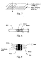
- a pin is inserted into one of the holes in a matrix board, as shown in Fig. 7.
- Each pin, such as pin 800, shown in Fig. 8 has two metal contacts 802A and 802B on the shaft, which create the connection between the circuits on different layers of the matrix board.
- Robotic cross connector 504 provides the capability to move a pin to an appropriate cross point and to insert the pin to form a connection at the cross point or remove the pin to break a cross connection.
- the mechanism of robotic cross connector 504 is capable of movement in three dimensions, using a separate motor for movement in each dimension.
- Z-coordinate motor 902 shown in Fig. 9, provides movement of the mechanism along the Z axis.
- a pin is carried, inserted and removed by a robotic "hand", such as hand 904A or 904B, which is part of robotic cross connector 504.
- Control circuitry 506 generates the signals necessary to control operation of robotic cross-connector 504, in response to commands from processor 508.
- Processor 508 generates the commands that are output to control circuitry 506 in response to commands received from the network management system via communication adapter 510.
- robotic cross connector 504 verifies that the connection has been successfully made, as shown in Fig. 10.
- a metal strip 1002 attached to each pin, such as pin 1004.
- the robot verifies the connection by sending a small current from one hand 1006A to the other hand 1006B.
- the metallic parts of the robot hand are electrically insulated.
- Hand 1006B is connected to the ground and hand 1006A is connected to current detector 1008.
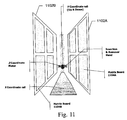
- FIG. 11 An example of matrix boards in relation to the robotic cross-connector is shown in Fig. 11. As shown, typically two mother boards 1102A and 1102B, upon which matrix boards 1104A - 1104N are mounted, one robotic cross-connector 1106, and the additional circuitry are grouped to form a cross connect system.
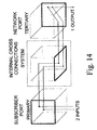
- Figs. 12 - 17 illustrate some standard 3 dimensional connection paths, which are completed by the Remote Cross-Connect Switch in response to commands.
Landscapes
- Engineering & Computer Science (AREA)
- Computer Networks & Wireless Communication (AREA)
- Signal Processing (AREA)
- Robotics (AREA)
- Data Exchanges In Wide-Area Networks (AREA)
- Telephonic Communication Services (AREA)
- Interface Circuits In Exchanges (AREA)
Applications Claiming Priority (2)
| Application Number | Priority Date | Filing Date | Title |
|---|---|---|---|
| US09/772,959 US20020101864A1 (en) | 2001-01-31 | 2001-01-31 | System and method for switching digital subscriber line |
| US772959 | 2001-01-31 |
Publications (2)
| Publication Number | Publication Date |
|---|---|
| EP1229706A2 true EP1229706A2 (de) | 2002-08-07 |
| EP1229706A3 EP1229706A3 (de) | 2004-10-27 |
Family
ID=25096729
Family Applications (1)
| Application Number | Title | Priority Date | Filing Date |
|---|---|---|---|
| EP01850146A Withdrawn EP1229706A3 (de) | 2001-01-31 | 2001-08-23 | System und Verfahren zum schalten von digitalen Teilnehmerleitungsdiensten |
Country Status (5)
| Country | Link |
|---|---|
| US (2) | US20020101864A1 (de) |
| EP (1) | EP1229706A3 (de) |
| CN (1) | CN1328882C (de) |
| CA (1) | CA2354989C (de) |
| CR (1) | CR6570A (de) |
Cited By (5)
| Publication number | Priority date | Publication date | Assignee | Title |
|---|---|---|---|---|
| WO2006063951A1 (en) * | 2004-12-14 | 2006-06-22 | Marconi Communications Limited | Provision of alternative telecommunication services |
| EP1798993A1 (de) * | 2005-12-13 | 2007-06-20 | Huawei Technologies Co., Ltd. | Kommunikationssystem für sicheren Fernzugriff und Verfahren dafür |
| EP1761013A4 (de) * | 2005-05-25 | 2007-08-08 | Huawei Tech Co Ltd | Breitbandgerät für zentralvermittlungsstellen mit selbstdetektionsfähigkeit und zugehöriges verfahren |
| EP1931167A1 (de) * | 2006-12-07 | 2008-06-11 | 3M Innovative Properties Company | Schaltmodul in einer Verteilstelle im Telekommunikationsbereich und Baugruppen damit, sowie Verwendungsverfahren dafür |
| EP1683303A4 (de) * | 2003-09-26 | 2013-01-02 | Bce Inc | Verfahren und system zur verbindungsverifikation |
Families Citing this family (12)
| Publication number | Priority date | Publication date | Assignee | Title |
|---|---|---|---|---|
| US20020101864A1 (en) * | 2001-01-31 | 2002-08-01 | Joe Teixeira | System and method for switching digital subscriber line |
| US7327673B1 (en) * | 2001-08-31 | 2008-02-05 | At&T Delaware Intellectual Property, Inc. | Asymmetric digital subscriber line provision flow control on digital subscriber line access multiplexer switches |
| US7139244B1 (en) * | 2001-09-21 | 2006-11-21 | Bellsouth Ip Corporation | System and method for remotely inventorying multiplexing element switching fabric |
| ATE406752T1 (de) * | 2003-12-16 | 2008-09-15 | Ericsson Telefon Ab L M | Ethernet-dsl-zugangsmultiplexer und verfahren zur bereitstellung einer dynamischen dienstauswahl und endbenutzerkonfiguration |
| DE102005022689B4 (de) * | 2005-05-18 | 2007-09-20 | Adc Gmbh | Aktive Verteilereinrichtung im Teilnehmeranschlussbereich |
| DE102005022547B4 (de) * | 2005-05-18 | 2008-07-03 | Adc Gmbh | Verteilereinrichtung im Teilnehmeranschlussbereich |
| US8437344B2 (en) * | 2006-03-07 | 2013-05-07 | Adc Telecommunications, Inc. | Telecommunication distribution device with multi-circuit board arrangement |
| US20070211882A1 (en) * | 2006-03-07 | 2007-09-13 | Francois Hatte | Control method for a telecommunication distribution system |
| US20070211883A1 (en) * | 2006-03-07 | 2007-09-13 | Jorg Franzke | Telecommunications device having distribution units arranged in block configuration |
| US20070211740A1 (en) * | 2006-03-07 | 2007-09-13 | Jorg Franzke | Telecommunications distribution system with line sharing |
| US8483369B2 (en) * | 2006-06-06 | 2013-07-09 | Adaptive Spectrum And Signal Alignment, Inc. | DSL system |
| US8199748B2 (en) * | 2007-07-26 | 2012-06-12 | Verizon Services Corp. | Automated configuration of a digital cross connect |
Family Cites Families (34)
| Publication number | Priority date | Publication date | Assignee | Title |
|---|---|---|---|---|
| US5455856A (en) * | 1993-04-21 | 1995-10-03 | Bell Communications Research, Inc. | Method and system for partially automating feeder and distribution cable cross-connects |
| EP0712542B1 (de) * | 1993-08-06 | 2003-03-19 | Kenneth James Warburton | Leitungsverteiler |
| JPH0787538A (ja) * | 1993-09-17 | 1995-03-31 | Fujitsu Ltd | 加入者端局装置 |
| US5619562A (en) * | 1995-02-06 | 1997-04-08 | Bell Atlantic Network Services, Inc. | Method and system for remotely activating/changing subscriber services in a public switched telephone network |
| US6026144A (en) * | 1996-02-23 | 2000-02-15 | Lucent Technologies Inc. | Method for improving the administration of the telephone local loop plant |
| US5831979A (en) * | 1996-06-21 | 1998-11-03 | Lucent Technologies Inc. | Method and apparatus for crossconnecting transmission members in the outside distribution plant of a telecommunications network for providing access to customer lines to a plurality of service providers |
| JP3377688B2 (ja) * | 1996-07-23 | 2003-02-17 | アンリツ株式会社 | Isdn加入者線多重化装置 |
| US6031904A (en) * | 1996-10-23 | 2000-02-29 | Nortel Networks Corporation | Service order mechanism for telephone subscriber |
| US6069949A (en) * | 1996-10-28 | 2000-05-30 | Nynex Science And Technology Inc. | Central office providing services for high usage customers |
| US6072793A (en) * | 1997-06-12 | 2000-06-06 | Lucent Technologies Inc. | Electronically controlled main distributing frame |
| US6421322B1 (en) * | 1997-11-17 | 2002-07-16 | Adc Telecommunications, Inc. | System and method for electronically identifying connections of a cross-connect system |
| US6542267B1 (en) * | 1997-11-24 | 2003-04-01 | Paul James Nicholson | Light ramp 2000 fiber optic local access architecture |
| US6359881B1 (en) * | 1997-12-31 | 2002-03-19 | At&T Corp. | Hybrid fiber twisted pair local loop network service architecture |
| US6347075B1 (en) * | 1997-12-31 | 2002-02-12 | At&T Corp. | Circuit to provide backup telephone service for a multiple service access system using a twisted pair |
| EP1061700B1 (de) * | 1998-11-10 | 2012-02-22 | Kabushiki Kaisha Toshiba | Matrixschalter |
| US6219354B1 (en) * | 1998-12-30 | 2001-04-17 | Qwest Communications International Inc. | VDSL cabinet designs and configurations |
| US6335936B1 (en) * | 1999-04-22 | 2002-01-01 | Ameritech Corporation | Wide area communication networking |
| US6285671B1 (en) * | 1999-04-22 | 2001-09-04 | Ameritech Corporation | Method and system for providing facsimile service over a digital subscriber line |
| US6434141B1 (en) * | 1999-05-26 | 2002-08-13 | Bigband Networks, Inc. | Communication management system and method |
| US6359858B1 (en) * | 1999-06-03 | 2002-03-19 | Fujitsu Network Communications, Inc. | Switching redundancy control |
| US6647117B1 (en) * | 1999-08-16 | 2003-11-11 | Nortel Networks Limited | Continuity of voice carried over DSL during power failure |
| AR026942A1 (es) * | 1999-12-14 | 2003-03-05 | Adc Telecommunications Inc | Disposiciones y metodos para administrar electronicamente conexiones de telecomunicaciones de lineas de abonados digitales (lad) |
| US6343114B1 (en) * | 1999-12-30 | 2002-01-29 | Turnstone Systems, Inc. | Remotely addressable maintenance unit |
| US6404763B1 (en) * | 2000-02-11 | 2002-06-11 | General Bandwidth Inc. | System and method for communicating telecommunication information between network equipment and a plurality of local loop circuits |
| US6466573B1 (en) * | 2000-02-11 | 2002-10-15 | General Bandwidth Inc. | System and method for communicating telecommunication information between a telecommunication switch and customer premises equipment |
| US6295339B1 (en) * | 2000-02-18 | 2001-09-25 | Harris Corporation | Audio verification of digital subscriber line connection |
| US6434221B1 (en) * | 2000-05-17 | 2002-08-13 | Sunrise Telecom, Inc. | Digital subscriber line access and network testing multiplexer |
| US6584148B1 (en) * | 2000-06-02 | 2003-06-24 | Nokia Inc. | System and method for testing digital subscriber lines |
| US6836509B1 (en) * | 2000-07-17 | 2004-12-28 | Lucent Technologies Inc. | Dsl- compatible pots line card |
| US6470074B2 (en) * | 2000-07-19 | 2002-10-22 | Nhc Communications, Inc. | System and method for providing data and voice services on a shared line |
| US6831930B1 (en) * | 2000-11-06 | 2004-12-14 | Adc Telecommunications, Inc. | Access panel for network end linesharing ADSL/POTS splitter applications |
| US20020101851A1 (en) * | 2000-11-29 | 2002-08-01 | Blake John D. | Method of and apparatus for providing multiple independent voice telephone line circuits using and including a packet voice device |
| US6415022B1 (en) * | 2000-12-07 | 2002-07-02 | Global Switches Corporation | User programmable telephone wiring access terminal |
| US20020101864A1 (en) * | 2001-01-31 | 2002-08-01 | Joe Teixeira | System and method for switching digital subscriber line |
-
2001
- 2001-01-31 US US09/772,959 patent/US20020101864A1/en not_active Abandoned
- 2001-08-10 CA CA002354989A patent/CA2354989C/en not_active Expired - Fee Related
- 2001-08-23 EP EP01850146A patent/EP1229706A3/de not_active Withdrawn
-
2002
- 2002-01-30 CR CR6570A patent/CR6570A/es not_active Application Discontinuation
- 2002-01-31 CN CNB021205914A patent/CN1328882C/zh not_active Expired - Fee Related
- 2002-02-01 US US10/060,172 patent/US20020101850A1/en not_active Abandoned
Cited By (8)
| Publication number | Priority date | Publication date | Assignee | Title |
|---|---|---|---|---|
| EP1683303A4 (de) * | 2003-09-26 | 2013-01-02 | Bce Inc | Verfahren und system zur verbindungsverifikation |
| WO2006063951A1 (en) * | 2004-12-14 | 2006-06-22 | Marconi Communications Limited | Provision of alternative telecommunication services |
| US8280033B2 (en) | 2004-12-14 | 2012-10-02 | Ericsson Ab | Provision of alternative telecommunication services |
| EP1761013A4 (de) * | 2005-05-25 | 2007-08-08 | Huawei Tech Co Ltd | Breitbandgerät für zentralvermittlungsstellen mit selbstdetektionsfähigkeit und zugehöriges verfahren |
| EP1798993A1 (de) * | 2005-12-13 | 2007-06-20 | Huawei Technologies Co., Ltd. | Kommunikationssystem für sicheren Fernzugriff und Verfahren dafür |
| EP1931167A1 (de) * | 2006-12-07 | 2008-06-11 | 3M Innovative Properties Company | Schaltmodul in einer Verteilstelle im Telekommunikationsbereich und Baugruppen damit, sowie Verwendungsverfahren dafür |
| WO2008073699A3 (en) * | 2006-12-07 | 2008-11-20 | 3M Innovative Properties Co | A switch module in a distribution point in the field of telecommunications and assemblies including as well as methods of using same |
| RU2444858C2 (ru) * | 2006-12-07 | 2012-03-10 | 3М Инновейтив Пропертиз Компани | Коммутационный модуль в распределительном узле в области телекоммуникации и сборочные узлы, а также способы их применения |
Also Published As
| Publication number | Publication date |
|---|---|
| CN1328882C (zh) | 2007-07-25 |
| US20020101864A1 (en) | 2002-08-01 |
| US20020101850A1 (en) | 2002-08-01 |
| CN1388679A (zh) | 2003-01-01 |
| HK1051277A1 (en) | 2003-07-25 |
| CA2354989A1 (en) | 2002-07-31 |
| CA2354989C (en) | 2006-11-07 |
| EP1229706A3 (de) | 2004-10-27 |
| CR6570A (es) | 2004-05-25 |
Similar Documents
| Publication | Publication Date | Title |
|---|---|---|
| CA2354955C (en) | System and method for providing analog telephone service when voice over ip over sdsl service is interrupted due to power failure | |
| US6470074B2 (en) | System and method for providing data and voice services on a shared line | |
| US6766008B2 (en) | System and method for switching telecommunications service in a multiple dwelling unit/multiple tenant unit environment | |
| CA2354989C (en) | System and method for switching digital subscriber line service | |
| US6826280B1 (en) | Systems and methods for managing digital subscriber line (DSL) telecommunications connections | |
| US6546089B1 (en) | Method and system for supporting a lifeline associated with voice over DSL | |
| US6574313B1 (en) | Voice over DSL method and system for supporting a lifeline | |
| ZA200205390B (en) | Systems and methods for electronically managing digital subscriber line (DSL) telecommunications connections. | |
| US20030142811A1 (en) | CLEC to CLEC service provisioning | |
| EP1204266A1 (de) | Verfahren und Vorichtung zur Bereistellung einer Stützverbindung in einem Telecommunikationssystem | |
| HK1051277B (en) | System and method for switching digital subscriber line service | |
| US7583689B2 (en) | Distributed communication equipment architectures and techniques | |
| EP2276225B1 (de) | Verfahren zum Testen des Breitbanddienstes digitaler Teilnehmerleitungen | |
| EP1356687A2 (de) | Clec zu clec servicebereitstellung | |
| CN1290308C (zh) | 用于在电信系统中提供宽带接入的设备和方法 | |
| US20030005069A1 (en) | Method and apparatus capable of enabling a network interface device to be provisioned remotely | |
| HK1051276A1 (en) | System and method for providing data and voice services on a shared line | |
| HK1051276B (en) | System and method for providing data and voice services on a shared line | |
| HK1071980A (en) | Clec to clec service provisioning | |
| HK1051280A (en) | System and method for switching telecommunications service in a multiple dwelling unit/multiple tenant unit environment | |
| HK1052094A (en) | System and method for providing analog telephone service when voice over ip over sdsl service is interrupted due to power failure |
Legal Events
| Date | Code | Title | Description |
|---|---|---|---|
| PUAI | Public reference made under article 153(3) epc to a published international application that has entered the european phase |
Free format text: ORIGINAL CODE: 0009012 |
|
| AK | Designated contracting states |
Kind code of ref document: A2 Designated state(s): AT BE CH CY DE DK ES FI FR GB GR IE IT LI LU MC NL PT SE TR |
|
| AX | Request for extension of the european patent |
Free format text: AL;LT;LV;MK;RO;SI |
|
| PUAL | Search report despatched |
Free format text: ORIGINAL CODE: 0009013 |
|
| AK | Designated contracting states |
Kind code of ref document: A3 Designated state(s): AT BE CH CY DE DK ES FI FR GB GR IE IT LI LU MC NL PT SE TR |
|
| AX | Request for extension of the european patent |
Extension state: AL LT LV MK RO SI |
|
| 17P | Request for examination filed |
Effective date: 20050422 |
|
| AKX | Designation fees paid |
Designated state(s): AT BE CH CY DE DK ES FI FR GB GR IE IT LI LU MC NL PT SE TR |
|
| STAA | Information on the status of an ep patent application or granted ep patent |
Free format text: STATUS: THE APPLICATION IS DEEMED TO BE WITHDRAWN |
|
| 18D | Application deemed to be withdrawn |
Effective date: 20070201 |