EP1229729A2 - Tintenstrahldruck mit mehreren Markierern für erhöhte Druckgeschwindigkeit - Google Patents
Tintenstrahldruck mit mehreren Markierern für erhöhte Druckgeschwindigkeit Download PDFInfo
- Publication number
- EP1229729A2 EP1229729A2 EP02002141A EP02002141A EP1229729A2 EP 1229729 A2 EP1229729 A2 EP 1229729A2 EP 02002141 A EP02002141 A EP 02002141A EP 02002141 A EP02002141 A EP 02002141A EP 1229729 A2 EP1229729 A2 EP 1229729A2
- Authority
- EP
- European Patent Office
- Prior art keywords
- printhead
- plane
- color
- data signals
- printheads
- Prior art date
- Legal status (The legal status is an assumption and is not a legal conclusion. Google has not performed a legal analysis and makes no representation as to the accuracy of the status listed.)
- Ceased
Links
Images


Classifications
-
- H—ELECTRICITY
- H04—ELECTRIC COMMUNICATION TECHNIQUE
- H04N—PICTORIAL COMMUNICATION, e.g. TELEVISION
- H04N1/00—Scanning, transmission or reproduction of documents or the like, e.g. facsimile transmission; Details thereof
- H04N1/40—Picture signal circuits
- H04N1/405—Halftoning, i.e. converting the picture signal of a continuous-tone original into a corresponding signal showing only two levels
- H04N1/4051—Halftoning, i.e. converting the picture signal of a continuous-tone original into a corresponding signal showing only two levels producing a dispersed dots halftone pattern, the dots having substantially the same size
- H04N1/4052—Halftoning, i.e. converting the picture signal of a continuous-tone original into a corresponding signal showing only two levels producing a dispersed dots halftone pattern, the dots having substantially the same size by error diffusion, i.e. transferring the binarising error to neighbouring dot decisions
-
- B—PERFORMING OPERATIONS; TRANSPORTING
- B41—PRINTING; LINING MACHINES; TYPEWRITERS; STAMPS
- B41J—TYPEWRITERS; SELECTIVE PRINTING MECHANISMS, i.e. MECHANISMS PRINTING OTHERWISE THAN FROM A FORME; CORRECTION OF TYPOGRAPHICAL ERRORS
- B41J2/00—Typewriters or selective printing mechanisms characterised by the printing or marking process for which they are designed
- B41J2/005—Typewriters or selective printing mechanisms characterised by the printing or marking process for which they are designed characterised by bringing liquid or particles selectively into contact with a printing material
- B41J2/01—Ink jet
- B41J2/21—Ink jet for multi-colour printing
- B41J2/2132—Print quality control characterised by dot disposition, e.g. for reducing white stripes or banding
- B41J2/2139—Compensation for malfunctioning nozzles creating dot place or dot size errors
-
- B—PERFORMING OPERATIONS; TRANSPORTING
- B41—PRINTING; LINING MACHINES; TYPEWRITERS; STAMPS
- B41J—TYPEWRITERS; SELECTIVE PRINTING MECHANISMS, i.e. MECHANISMS PRINTING OTHERWISE THAN FROM A FORME; CORRECTION OF TYPOGRAPHICAL ERRORS
- B41J2/00—Typewriters or selective printing mechanisms characterised by the printing or marking process for which they are designed
- B41J2/485—Typewriters or selective printing mechanisms characterised by the printing or marking process for which they are designed characterised by the process of building-up characters or image elements applicable to two or more kinds of printing or marking processes
- B41J2/505—Typewriters or selective printing mechanisms characterised by the printing or marking process for which they are designed characterised by the process of building-up characters or image elements applicable to two or more kinds of printing or marking processes from an assembly of identical printing elements
- B41J2/51—Typewriters or selective printing mechanisms characterised by the printing or marking process for which they are designed characterised by the process of building-up characters or image elements applicable to two or more kinds of printing or marking processes from an assembly of identical printing elements serial printer type
-
- G—PHYSICS
- G06—COMPUTING OR CALCULATING; COUNTING
- G06K—GRAPHICAL DATA READING; PRESENTATION OF DATA; RECORD CARRIERS; HANDLING RECORD CARRIERS
- G06K15/00—Arrangements for producing a permanent visual presentation of the output data, e.g. computer output printers
- G06K15/02—Arrangements for producing a permanent visual presentation of the output data, e.g. computer output printers using printers
- G06K15/10—Arrangements for producing a permanent visual presentation of the output data, e.g. computer output printers using printers by matrix printers
- G06K15/102—Arrangements for producing a permanent visual presentation of the output data, e.g. computer output printers using printers by matrix printers using ink jet print heads
- G06K15/105—Multipass or interlaced printing
- G06K15/107—Mask selection
Definitions
- This invention relates to inkjet printing using two or more printheads of the same color to increase printing speed.
- Inkjet printing systems are in common use today.
- An ink jet printer forms a printed image by printing a pattern of individual dots at particular locations of an array defined for the printing medium.
- the locations are conveniently visualized as being small dots in a rectilinear array.
- the locations are sometimes "dot locations", “dot positions”, or “pixels”.
- the printing operation can be viewed as the filling of a pattern of dot locations with dots of ink.
- Ink jet printers print dots by ejecting very small drops of ink onto the print medium, and typically include a movable carriage that supports one or more printheads each having ink ejecting nozzles.
- the carriage traverses over the surface of the print medium, and the nozzles are controlled to eject drops of ink at appropriate times pursuant to command of a microcomputer or other controller, wherein the timing of the application of the ink drops is intended to correspond to the pattern of pixels of the image being printed.
- Color ink jet printers commonly employ a plurality of printheads, for example four, mounted in the print carriage to produce different colors.
- Each printhead contains ink of a different color, with the commonly used colors being cyan, magenta, yellow, and black.
- These base colors are produced by depositing a drop of the required color onto a dot location.
- Secondary or shaded colors are formed by depositing drops of different colors on adjacent dot locations; the human eye interprets the color mixing as the secondary or shading, through well known optical principles.
- the present invention relates to a method to print ink drops in an inkjet printer, and particularly to a printing system and method where at least one color ink can be printed by two (or more) printheads.
- the method divides the drops to be printed between the two printheads with purposes of higher printer velocity, higher image quality and higher print reliability.
- An objective of the invention is to provide higher speed modes by using an extra black print head in an inkjet printing system.
- An exemplary application for a printing system using the invention is in a large format printing system for the CAD market, i.e the technical user market (engineers, architects, and the like) who typically print line drawings and image renderings.
- the use of two black print heads enables a print speed of 60 inches per second (ips) and allows laying down two drops per 600 dpi cell (two drops are needed to provide fair optical density).
- a methodology is described to print with two black print heads in an inkjet printing system, i.e. how the black channel information is processed through the printing system data pipeline and gets separated to each print head in order to print either the same information or complementary information.
- the invention is not limited to increasing speed with two black printheads, but could be employed in using two or more printheads of the same color, e.g. two cyan printheads or three black printheads.
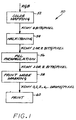
- FIG. 1 is a diagrammatic flow chart that functionally describes an exemplary data pipeline 50 for an inkjet printing system.
- the inkjet printing system is a color printing system which includes respective printheads for ejecting cyan (C), magenta (M), yellow (Y) and black (K) inks.
- Print data are provided from the printer driver in RGB (red-green-blue) format to a color mapping function 52, which maps the RGB data into KCMY data, at a resolution of 8 bits per pixel for this example.
- the color mapping function converts 8-bit (0-255 values) RGB data into 8-bit KCMY data using an interpolation table.
- the KCMY data is then processed by a half-toning function 54, to provide KCMY data at 1 or 2 bits per pixel.
- the half-toned data is processed by a PCL encapsulation function, to produce KCMY data at 1 or 2 bits per pixel.
- the PCL encapsulation re-formats the information so that the printer can interpret it; there is no change in resolution or in content for a given pixel.
- the PCL print data is then passed through a print mode masking function 58, and the masked data is employed to print droplets. This function distributes the print data in different passes for image quality purposes.
- a "channel” or “plane” for a given color refers to the pixel information to be printed with the given color.
- the black channel or plane propagates all the way down the pipeline 50 like the other channels/planes (CMY) from the contone stage (8-bit, coming from the driver) to the actual drops emitted from the printheads during step 60.
- CY channels/planes
- the separation of the black plane into two planes can occur in any of the steps in FIG. 1, when a fifth plane is added to handle the second black printhead, since there should preferably be a plane dependency between the two black printheads.
- An exemplary technique to make the plane separation is that the data for the two black printheads propagate all the way down the pipeline as a single black plane, i.e. through color mapping 52, half-toning 54 and PCL encapsulation 56, and at the masking level (step 58) the separation occurs.
- mask level separation occurs at the print mode/mask level 58.
- five printheads are defined so that different masks can be laid down for each of the black printheads, referred to as printheads K1 and K2.
- the two masks created are complementary, so that at the end of the total number of passes, all the required drops are fired as they were a single unique mask for black. An example of that is the following.
- the print mode is a 3-pass print mode, 600*600 dpi 2-bits (4 levels), in which the drops per level are 0, 1, 1, 2.
- the printing grid for this example is 2400*600 (half-toned horizontal resolution is divided by four), and the mask size is 64 x 32.
- the print mode has four levels, level 0, level 1, level 2 and level 3.
- Level 0 contains only 0s, and so all the relevant information is contained in levels 1, 2, 3. This is part of the architecture of this exemplary print engine.
- the single or unique mask for the case with only one black printhead K for this example is the following: Pass 1 / Level 1 1 0 0 0 0 0 0 0 0 1 0 0 0 0 0 0 0 1 0 0 0 0 0 0 0 0 0 0 0 0 0 0 / Level 2 1 0 0 0 0 0 0 0 0 1 0 0 0 0 0 0 0 1 0 0 0 0 0 0 0 0 1 0 0 0 0 0 0 0 0 0 0 0 0 0 / 0 Pass 1 / Level 3 1 1 0 0 0 0 0 0 0 1 1 0 0 0 0 0 0 0 1 1 0 0 0 0 0 0 0 0 0 0 0 0 0 0 0 0 0 0 0 0
- the foregoing example shows a mask of two rows and sixteen columns.
- the printer controller tiles down this elemental mask to the whole height of the printhead, so that facing the tiled mask to each individual nozzle in the printhead each row of the mask lines up with one nozzle of the printhead.
- Each mask row corresponds to the information to be fired by each nozzle where "1" means drop being fired and "0" means no drop is fired.
- the example also shows different masks for different passes and levels. This means that the dots are distributed along different print passes.
- the levels refer to the different levels of half-toning. The half-toning is used to enable multiple firing in each pixel location.
- the print engine is able to, for example, place one drop for level 1, three drops for level 2 and six drops for level 3. If there are four levels, level 0, level 1, level 2 and level 3, level 0 has no information.
- there is a mask for each mask for each level and for each color This allows combination of the different firing sequences of drops (single or multiple) of different color inks and in different instants of time (print passes).
- the exemplary unique (single printhead) mask shown above contains many 0s. If all the print masks are summed, all 1s, corresponding to the completion of all the information to be fired) would still not result. The reason for this is that a finer printing grid is used at the half-toning stage. For this exemplary embodiment, half-toning is done at 600 dpi, and the printing is at 2400 dpi, so that each pixel is divided into four locations. This finer grid allows for dot locations one next to the other, instead of one on top of the other in multi-drop printing.
- Multi-drop printing can be achieved by using several print passes.
- multi-drop printing can be achieved by using a finer grid than that of the half-toning (where the levels are defined), so that dots can be placed in adjacent pixel locations of the half-toning grid, even in just one pass, although there are print head firing frequency limitations.
- both ways are used to achieve multi-drop printing.
- Bits or levels of the half-toning function correspond to the drops per pixel in different ways. The following table shows the different possibilities.
- the unique mask for a single color can be of arbitrary size.
- the controller "tiles" the mask to the whole print file (vertically and horizontally). "Tiling" the mask is a known technique whereby a defined mask of limited dimensions, i.e. x pixels in width by y pixels in height, is replicated all through the height and width of the print file. For this example, there are only six levels, where six is the maximum number of drops to be fired, but there can be less or more.
- the masks in the different levels can be viewed as a big mask of different layers, one layer per level.
- two black print heads K1,K2 are employed, with two mask sets, as follows: K1 / Pass 1 / Level 1 1 0 0 0 0 0 0 0 0 0 0 0 0 0 0 0 0 0 0 0 0 0 0 0 0 1 0 0 0 0 0 0 0 0 0 0 K1 / Pass 1 / Level 2 1 0 0 0 0 0 0 0 0 0 0 0 0 0 0 0 0 0 0 0 0 0 0 0 1 0 0 0 0 0 0 0 0 0 K1 / Pass 1 / Level 3 1 0 0 0 0 0 0 0 0 0 1 0 0 0 0 0 0 0 0 0 1 0 0 0 0 0 0 0 0 0 K1 / Pass 2 / Level 1
- the two mask sets (K1 and K2) are each loaded with 50% of the drops, but other patterns could alternatively be employed, wherein an unequal drop distribution between the two printheads is used.
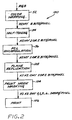
- FIG. 2 is a schematic flow diagram of a printing system data pipeline 100 which provides separation of the black data into two planes, for two black printheads K1/K2.
- This pipeline includes the initial three steps 52, 54, 56 as in the pipeline 50 of FIG. 1, to perform color mapping (52), half-toning (54) and PCL encapsulation (56) in the incoming print data.
- the print data from step 56 is passed to a plane replication function 102, which replicates the K data (single plane) into two identical black planes for the K1, K2 printheads, producing K1K2CMY data at 1 or 2 bits per pixel for this embodiment.
- This data is then passed to the print mode masking function 104, where the separate K1/K2 masks are applied to the data, as well as the CMY masks, producing K1K2CMY 0,1,2,...6... drops per pixel.
- the data from the print mode masking function is then passed to the print function to produce the actual drops during printing operations.
- the black plane is copied to a new one and thus the K information is exactly the same for this other K2 plane.
- K1 and K2 Complementary print masks are used to split the data between the two black printheads prior to printing.
- the mask sets for each plane are less than 100% coverage (for example, 50% and 50%). If not, twice the number of drops would be fired.
- more than two black printheads could be employed, e.g. by replicating the black plane twice, i.e. forming K1, K2, K3 planes, and then providing complementary print mask sets for the three planes.
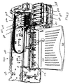
- FIG. 3 is an isometric view of an inkjet printing system 200 employing two printheads of the same color in accordance with an aspect of this invention.
- the printing system 200 is shown without its outer housing structure to expose the printheads.
- the printing system includes a frame structure 202 and a printhead carriage structure 204.
- the frame supports a slider bar 206, and the carriage structure is driven along the slider bar by a carriage drive system.
- An output media tray 210 is supported above an input media tray 212 which provides a source of print media.
- a pick system picks the top sheet of media from the tray 212, and a media drive system transports the picked sheet along a media path to the print zone generally indicated as 214.
- the carriage structure 204 has five printhead stalls for holding five removable inkjet printheads 220, 222, 224, 226, 228, which for this exemplary embodiment are C/K1/K2/M/Y printheads, respectively.
- the two black printheads are located between the cyan and magenta printheads.
- Other ordering of the respective printheads could be used. However, this ordering facilitates a technique placing cyan or magenta drops before and after a black drop to provide higher optical density for the black areas. These extra drops are not information in the print file, but are used to obtain a better ink-media interaction resulting in higher optical density.
- cyan drops are placed ahead of the two black drops (K1, K2), and in the reverse print direction, the magenta drops precede the two black drops.
- the printing system 200 further includes five off-carriage ink supplies 230, 232, 234, 236, 238, each for holding a supply of ink.
- Each ink supply is fluidicially coupled to a corresponding printhead by a fluid conduit, here including a flexible tube comprising tube set 240.
- a fluid conduit here including a flexible tube comprising tube set 240.
- the printheads are connected to corresponding ink supplies to replenish the ink supplies on-board each printhead.
- Each ink supply can be replaced when its ink is exhausted.
- FIG. 4 is a schematic block diagram of the control system for the printing system 200 of FIG. 3.
- a controller 250 such as a microcomputer or ASIC receives print job commands and data from a print job source 72, which can be a personal computer, digital camera or other source of print jobs.
- the controller implements the functions of the print data pipeline 100 (FIG. 2), acts on the received commands to activate the pick roller motor 260 to pick a sheet from the input tray 212, advance the sheet to the media drive, e.g. to a nip between a drive roller and pinch roller set, and activate the drive motor system 262 to advance the sheet onto the belt, and move the belt to advance the sheet to the print zone.
- the carriage drive 264 is driven by the controller to position the carriage 204 for commencement of a print job, and to scan the carriage along the slider rod 206. As this is done firing pulses are sent to the printheads 220-228.
- the controller receives encoder signals from the carriage encoder 268 to provide position data for the carriage.
- the controller is programmed to advance incrementally the sheet to position the sheet for successive swaths, and to eject the completed sheet into the output tray 210.
- FIGS. 3 and 4 represent an exemplary embodiment of an inkjet printing system embodying aspects of the invention.
- Other inkjet printing systems could alternatively be employed, including systems with disposable printhead cartridges and no off-carriage ink supplies, systems with greater than five printheads, by way of example only.
- the black print data is a unique plane until they reach the half-toning step.
- Two K planes are generated during half-toning.
- the data for each K plane is different, and these two different K planes propagate through the remainder of the pipeline, i.e. through the PCL ensapsulation and print mode masking steps to the printing step (FIG. 1).
- Further advantages can be optionally provided by using plane dependent half-toning, by using error diffusion half-toning, and by treating the two K planes as secondary colors in the half-toning algorithm.
- Conventional printmode masking is employed in this embodiment, i.e the masks for the two K planes are not complementary as in the embodiment of FIG. 2, and in fact are preferably identical.
- Error diffusion algorithms for half-toning are well known. In general, error diffusion is used to convert from the "continuous tone" (contone) stage of the information to the "half-toned" stage. In the contone stage, the information can be encoded with 8 bits, for example, and therefore the possible values of a channel are from 0 to 255 (example RGB values on a display or CMYK values sent from a driver to a printer). Thus, each pixel has the color information encoded with one byte (one byte is 8 bits) for each color or plane. If for example, the input format is CMYK, the pixel has possible values C[0-255], M[0-255], Y[0-255], K[0-255].
- the half-toning step provides a reduction in the amount of information for each pixel, while preserving overall color characteristics.
- the information for each color or plane is encoded with generally 1, 2 or 3 bits of information.
- a color channel enters the half-toning step with possible values [0-255], and output with only four possible values, namely 0, 1, 2, 3 (two bits of information can only represent four different values).
- the only possible output values for one color at the output are 0 or 1, since one bit only has two states.
- possible output values for the color of a pixel are [0-7], since 3 bits can encode 8 different values.
- the error diffusion principle is the following.
- the pixel When the pixel reaches the half-toning step, it is attributed an output value that minimizes the error, i.e., the mismatch between the output value that is attributed to the given color for the pixel and the input value of this given color for this pixel.
- the only possible output values are 0, 1, 2 or 3.
- none of the possible output levels or values (0, 1, 2, 3, or 0%, 33.3%, 66.6%, 100%) represents exactly the input value (140/255, or 54.9%), so an error is committed.
- a pixel enters with a cyan level of 45 (out of 255), and is attributed level 1 out of 4. This pixel is "over attributed" 7% on the cyan channel, i.e. the error is +7%. This error is then summed to the next pixel's input value of the same channel before deciding which output is given to the neighbor. For this example of a 7% error, this error would be added on the cyan channel before deciding which output is given to the neighboring pixel. This is the process of error diffusion.
- Plane dependent error diffusion goes one step further, as it defines dependencies between specific planes (generally between cyan and magenta). So in this case, the error committed over one plane is taken into account, but the sum of errors of each dependent plane is calculated for a pixel to decide its output value. This is described in U.S. 6,057,933, the entire contents of which are incorporated herein by this reference. This allows the avoidance of pixels accumulating drops from the dependent planes (say one pixel with cyan + magenta drops) if the neighboring pixels do not have drops, and therefore leads to a noticeable reduction of the "grainy" aspect on inkjet print samples.
- a second technique for separating the black plane into separate planes for the two black printheads i.e. for deciding which ink drops will be printed by each black printhead, is described.
- the separation of the black plane is done in the half-toning function.
- An exemplary embodiment of this technique takes advantage of the "plane dependant error diffusion" functionality described above, and described in U.S. 6,057,933, although the invention is not limited to error diffusion or plane dependent half-toning.
- the black plane is separated at the half-toning step, and the two black output planes (which carry different information) are printed using the classical processes as if they were different colors.
- the method is random and the droplet printing order is not deterministic.
- the following example will be applied to the example of a printer with two black printheads, such as printer 200 (FIG. 3).
- This alternate technique includes several steps:
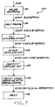
- FIG. 5 illustrates an exemplary flow diagram for implementing this technique for printing black ink droplets using two black print heads.
- FIG. 5 shows alternate cases, for an RGB driver as well as for a CMYK driver.
- the RGB contone print data 152 is received, and the black (K) data is extracted at 154 to provide KRGB data at 156.
- K black
- One technique is to use a lookup table that associates given values for K, R, G, B for a given set of input R, G, B values.
- Another technique is to use an algorithm, such as the following example: (i) Calculate the minimum (K o ) of R, G, B values.
- the K plane is copied to a G' color plane, producing RGBG' print data at 160.
- a half-toning process is then performed on the data, producing half-toned CMYC"Y" data at 174.
- the data are independent of the particular driver, and the C' and Y' planes are set to the K1, K2 planes respectively, at 176, producing print data CMYK1K2 data at 178.
- This data are now passed through the classical masking process (step 58, FIG. 1), where K1, K2 are treated as if they were different colors, and the drops are ejected.
- the masks used to print K1, K2 in this case are not complementary, and in fact can be identical.
- the masks with this alternate embodiment will deliver any pixel information from the color plane K1 or K2 to the print media, unlike the case with the first embodiment (FIG. 2) where a drop is fired by either one or the other black printhead.
- the second embodiment takes advantage of the plane dependent error diffusion half-toning technique.
- ink drops from primary colors will be calculated and assigned to pixels, following a half-toning technique that will randomize the spatial positions of the drops for each of the primary colors.
- Plane dependent error diffusion techniques provides some level of spatial exclusion, so that drops fired by each of the primary color printheads will tend to occupy different places on the print media. This provides less granularity to the printed images, and this is particularly appropriate for this application where ink drops are to be printed with the same color (black in this example).
- this second technique for separating the black plane into two planes could be employed with other techniques for half-toning, and is not limited to error diffusion half-toning.
- Another technique for separating the black plane into two planes is that one black print head is mainly printing all the black pixels that contain low density (1 or 2 drops). The other black printhead helps out with those pixels demanding more drops so that these can be printed in less passes. Thus, for this alternate embodiment, more than one black ink drop is delivered to the pixels on the print media so that the desired ink density is achieved.
- Exemplary multilevel printing techniques are employed in the Hewlett-Packard PhotoRet system, for example, used in some HP DeskJet printers such as the HP DeskJet 970 and the Professional Series 2000. Multi-level printing is illustrated in the following table. 2-Bit Encoding Equivalent in # of drops (exemplary only) Level 0 00 0 Level 1 01 1 Level 2 10 2 Level 3 11 4
- certain of the levels e.g. levels 00, 01, 10, are assigned to the first black printhead (K1), and the level 11 is assigned to the second black printhead (K2).
- the second black printhead (K2) will fire 4 drops on that pixel, whereas a pixel value of 01 or 10 will be printed by the first printhead (K1).
- this third embodiment is particularly adapted to a printer having the capability to print multiple dots per pixel, for example 2 bits or four levels.
- the output pixel data levels or values are divided between the printheads of the same color, so that for example one prints the dots for lower levels and another prints higher levels, or in the case of three printheads of the same color, a third printhead prints the dots for an intermediate level(s).
- the result of a split between lower and higher levels is that one black printhead does most of the work and is occasionally helped by the second black printhead for very dark areas. This will mean that the first printhead will have to be replaced more frequently, and will lay down more ink, but that the second printhead will need to be replaced only very infrequently.
- FIG. 6 illustrates an exemplary data pipeline for implementing this embodiment of the invention.
- steps 52, 54, 56 and 102 are identical to the corresponding steps of the pipeline shown in FIG. 2, and result in two identical black data planes, K1, K2.
- Step 120 is a plane filtering step.
- the two identical planes for K1 and K2 are filtered or divided in such a way that the pixel data for levels assigned to one printhead are set to Os in the data plane of the other printhead, and vice versa.
- the pixel data for level 3 in the K1 data plane is set to all 0's since level 3 data is to be printed by the K2 printhead, and the pixel data for levels 1 and 2 in the K2 data plane are set to all 0's, since levels 1 and 2 are to be printed by the K1 printhead.
- Standard printmode masking and printing steps 122 and 106 follow.
- the levels could be assigned to K1 and K2 respectively, by setting the print mode mask levels for one black plane which are assigned to the other plane to all 0's, and vice versa.
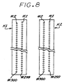
- error hiding can be performed between the two printheads of the same color very easily and effectively. That is, if a nozzle on one printhead fails, the data that should have been printed by that nozzle can be redirected to the equivalent nozzle, in the same relative location, on the other printhead. This in turn means that the error hiding or nozzle substitution can be performed within the same swath. In contrast, if error hiding is performed within the same printhead, then, since each nozzle passes over a unique part of the print media, the backup nozzle cannot print the failed nozzle's data in the same pass, but must wait for a media advance.
- Step 130 indicates a step of identifying failed nozzles, e.g. nozzles which do not fire or which misdirect their ink drops.
- the nozzle arrays for printheads K1 and K2 will be tested to identify failed nozzles. Techniques for identifying failed nozzles are known in the art.
- the printer can periodically check for failed nozzles by printing a test pattern on a print medium, and then optically scan the test image with a carriage-mounted optical sensor to detect nozzles which have failed.
- Another technique is to use an optical drop detector in a service station to detect blocked or misdirected nozzles. Suitable techniques are described in the above-references application numbers 08/810,467 and 09/506,740.
- the step 130 can be performed each time a print job is to be printed, or periodically and the results saved for use until another test of the nozzles is performed.
- the print mode masking step 132 is performed.
- the same complimentary masks as described above with respect to the embodiment of FIG. 2 provide the initial masks to be applied to the K1 and K2 data planes.
- the data that should have been printed by the failed nozzles on one black printhead are redirected to the equivalent nozzle, in the same relative location, on the other black printhead.
- FIG. 8 shows exemplary nozzle arrays for K1 and K2. Assume for example that nozzle #2 of K1 has failed. The data which should have been printed by that nozzle is instead printed by nozzle #2 of K2.
- the present invention relates to a method to print ink drops in an inkjet printer, and particularly to a printing system and method where at least one color ink can be printed by two (or more) printheads.
- the method divides the drops to be printed between the two printheads with purposes of higher printer velocity, higher image quality and higher print reliability.
Landscapes
- Engineering & Computer Science (AREA)
- Physics & Mathematics (AREA)
- Mathematical Physics (AREA)
- General Engineering & Computer Science (AREA)
- General Physics & Mathematics (AREA)
- Theoretical Computer Science (AREA)
- Multimedia (AREA)
- Signal Processing (AREA)
- Quality & Reliability (AREA)
- Ink Jet (AREA)
- Particle Formation And Scattering Control In Inkjet Printers (AREA)
Applications Claiming Priority (2)
| Application Number | Priority Date | Filing Date | Title |
|---|---|---|---|
| US773052 | 1991-10-08 | ||
| US09/773,052 US6471332B1 (en) | 2001-01-31 | 2001-01-31 | Multiple marker inkjet printing for increased print speed |
Publications (2)
| Publication Number | Publication Date |
|---|---|
| EP1229729A2 true EP1229729A2 (de) | 2002-08-07 |
| EP1229729A3 EP1229729A3 (de) | 2006-02-08 |
Family
ID=25097053
Family Applications (1)
| Application Number | Title | Priority Date | Filing Date |
|---|---|---|---|
| EP02002141A Ceased EP1229729A3 (de) | 2001-01-31 | 2002-01-29 | Tintenstrahldruck mit mehreren Markierern für erhöhte Druckgeschwindigkeit |
Country Status (2)
| Country | Link |
|---|---|
| US (1) | US6471332B1 (de) |
| EP (1) | EP1229729A3 (de) |
Families Citing this family (11)
| Publication number | Priority date | Publication date | Assignee | Title |
|---|---|---|---|---|
| US7283686B2 (en) * | 2003-04-14 | 2007-10-16 | Hewlett-Packard Development Company, L.P. | Image processor |
| US6857723B2 (en) * | 2003-04-18 | 2005-02-22 | Lexmark International, Inc. | Method, printer and printhead driver for printing using two printheads |
| JP2006033006A (ja) * | 2004-07-12 | 2006-02-02 | Seiko Epson Corp | 画像処理装置、及びドットデータ生成方法 |
| WO2006017800A2 (en) | 2004-08-06 | 2006-02-16 | Secocmbe S Dana | Means for higher speed inkjet printing |
| US20060103689A1 (en) * | 2004-11-18 | 2006-05-18 | Vinas Santiago G | Method for splitting a print image data plane for printing with multiple printheads |
| US8289568B1 (en) | 2009-02-19 | 2012-10-16 | Hewlett-Packard Development Company, L.P. | Printing using variable pixel-replication factors |
| US8469487B2 (en) * | 2010-05-28 | 2013-06-25 | Hewlett-Packard Development Company, L.P. | Inkjet printing apparatus and method for printing a plurality of pixels |
| US9272301B2 (en) | 2013-03-01 | 2016-03-01 | S. Dana Seccombe | Apparatus and method for non-contact manipulation, conditioning, shaping and drying of surfaces |
| WO2016014060A1 (en) | 2014-07-24 | 2016-01-28 | Hewlett-Packard Development Company, L.P. | Creating image data for a tile of an image |
| WO2016175812A1 (en) | 2015-04-30 | 2016-11-03 | Hewlett-Packard Development Company, L.P. | Dual and single drop weight printing |
| US10015366B2 (en) * | 2016-03-04 | 2018-07-03 | Esko Software Bvba | Variable resolution lookup table for accelerated color conversion |
Citations (5)
| Publication number | Priority date | Publication date | Assignee | Title |
|---|---|---|---|---|
| US5509085A (en) | 1992-10-07 | 1996-04-16 | Seiko Epson Corporation | Image processor and printing apparatus which perform binary coding of color components |
| EP0738068A2 (de) | 1995-04-03 | 1996-10-16 | Xerox Corporation | Zufallsdrucktechniquen für Drucker mit flüssiger Tinte |
| EP0960739A2 (de) * | 1998-05-29 | 1999-12-01 | Canon Kabushiki Kaisha | System zum komplementären Aufzeichnen mit mehrfachen Abtastung |
| EP0982143A2 (de) | 1998-08-27 | 2000-03-01 | Canon Kabushiki Kaisha | Druckverfahren und Drucker |
| EP1010531A1 (de) | 1998-12-14 | 2000-06-21 | Hewlett-Packard Company | Verfahren und Gerät zum Verdecken von Fehlern beim inkrementellen Einzeldurchgangsdrucken |
Family Cites Families (8)
| Publication number | Priority date | Publication date | Assignee | Title |
|---|---|---|---|---|
| US5428377A (en) * | 1992-08-11 | 1995-06-27 | Xerox Corporation | Color spatial filtering for thermal ink jet printers |
| ATE185321T1 (de) * | 1993-07-30 | 1999-10-15 | Canon Kk | Bildausgabeanlage und bilderzeugungsgerät zur korrektur von ungleichmässigkeiten in der dichte |
| US5764254A (en) * | 1993-10-29 | 1998-06-09 | Hewlett-Packard Company | Alignment of differently sized printheads in a printer |
| US5930019A (en) * | 1996-12-16 | 1999-07-27 | Fuji Xerox Co., Ltd. | Light scanning device, optical device, and scanning method of optical device |
| US6283572B1 (en) | 1997-03-04 | 2001-09-04 | Hewlett-Packard Company | Dynamic multi-pass print mode corrections to compensate for malfunctioning inkjet nozzles |
| US6010205A (en) * | 1997-03-12 | 2000-01-04 | Raster Graphics Inc. | Method and apparatus for improved printing |
| US6057933A (en) | 1997-10-30 | 2000-05-02 | Hewlett-Packard Company | Table based fast error diffusion halftoning technique |
| EP1033251B1 (de) | 1999-02-19 | 2003-05-28 | Hewlett-Packard Company, A Delaware Corporation | Druckverfahren zum automatischen Kompensieren von fehlerhaften Tintenstrahldüsen |
-
2001
- 2001-01-31 US US09/773,052 patent/US6471332B1/en not_active Expired - Lifetime
-
2002
- 2002-01-29 EP EP02002141A patent/EP1229729A3/de not_active Ceased
Patent Citations (5)
| Publication number | Priority date | Publication date | Assignee | Title |
|---|---|---|---|---|
| US5509085A (en) | 1992-10-07 | 1996-04-16 | Seiko Epson Corporation | Image processor and printing apparatus which perform binary coding of color components |
| EP0738068A2 (de) | 1995-04-03 | 1996-10-16 | Xerox Corporation | Zufallsdrucktechniquen für Drucker mit flüssiger Tinte |
| EP0960739A2 (de) * | 1998-05-29 | 1999-12-01 | Canon Kabushiki Kaisha | System zum komplementären Aufzeichnen mit mehrfachen Abtastung |
| EP0982143A2 (de) | 1998-08-27 | 2000-03-01 | Canon Kabushiki Kaisha | Druckverfahren und Drucker |
| EP1010531A1 (de) | 1998-12-14 | 2000-06-21 | Hewlett-Packard Company | Verfahren und Gerät zum Verdecken von Fehlern beim inkrementellen Einzeldurchgangsdrucken |
Also Published As
| Publication number | Publication date |
|---|---|
| US20020145643A1 (en) | 2002-10-10 |
| EP1229729A3 (de) | 2006-02-08 |
| US6471332B1 (en) | 2002-10-29 |
Similar Documents
| Publication | Publication Date | Title |
|---|---|---|
| US8272710B2 (en) | Bi-directional print masking | |
| JP5434015B2 (ja) | 印刷装置 | |
| US11531854B2 (en) | Image processing apparatus, image processing method and storage medium | |
| JP7589298B2 (ja) | 画像処理装置およびプログラム | |
| US6471332B1 (en) | Multiple marker inkjet printing for increased print speed | |
| US5923349A (en) | Density-based print masking for photographic-quality ink-jet printing | |
| JP5147862B2 (ja) | インクジェット記録装置およびインクジェット記録方法 | |
| EP1506871B1 (de) | Tintenstrahldruckverfahren, Vorrichtung und System | |
| US6834936B2 (en) | Ink jet printing apparatus and ink jet printing method | |
| US20080158281A1 (en) | Image forming apparatus and control method thereof | |
| US20030081023A1 (en) | Method and apparatus of optimizing discrete drop volumes for multidrop capable inkjet printers | |
| JP2010076216A (ja) | 印刷装置および印刷方法 | |
| US8976416B2 (en) | Image processing apparatus and method thereof | |
| US8462383B2 (en) | Bidirectional multi-pass inkjet printer suppressing density unevenness based on image information and scan line position of each dot | |
| US7497538B2 (en) | Method of multipass printing using a plurality of halftone patterns of dots | |
| JP2000135801A (ja) | 印刷装置 | |
| US6491374B1 (en) | Methods and apparatuses for printing with uniform and non-uniform print mask functions | |
| US6749280B2 (en) | Recording apparatus, recording method therefor and program therefor | |
| US7125091B2 (en) | Method for creating printing data applied to a printer capable of generating ink droplets of different sizes | |
| JP2018111287A (ja) | 画像処理装置および画像処理方法 | |
| JP7543020B2 (ja) | 画像処理装置、画像処理方法、およびプログラム | |
| US20040196476A1 (en) | Online bi-directional color calibration | |
| JP5564771B2 (ja) | 印刷装置、印刷方法、コンピュータプログラム、記録媒体、印刷媒体、および、プリンタ | |
| JP6021345B2 (ja) | 画像記録装置および画像記録方法 | |
| JP5812670B2 (ja) | 画像処理装置、画像処理方法および画像記録装置 |
Legal Events
| Date | Code | Title | Description |
|---|---|---|---|
| PUAI | Public reference made under article 153(3) epc to a published international application that has entered the european phase |
Free format text: ORIGINAL CODE: 0009012 |
|
| AK | Designated contracting states |
Kind code of ref document: A2 Designated state(s): AT BE CH CY DE DK ES FI FR GB GR IE IT LI LU MC NL PT SE TR |
|
| AX | Request for extension of the european patent |
Free format text: AL;LT;LV;MK;RO;SI |
|
| PUAL | Search report despatched |
Free format text: ORIGINAL CODE: 0009013 |
|
| AK | Designated contracting states |
Kind code of ref document: A3 Designated state(s): AT BE CH CY DE DK ES FI FR GB GR IE IT LI LU MC NL PT SE TR |
|
| AX | Request for extension of the european patent |
Extension state: AL LT LV MK RO SI |
|
| RIC1 | Information provided on ipc code assigned before grant |
Ipc: H04N 1/405 20060101AFI20051220BHEP Ipc: G06K 15/10 20060101ALI20020504BHEP |
|
| 17P | Request for examination filed |
Effective date: 20060807 |
|
| AKX | Designation fees paid |
Designated state(s): DE GB |
|
| 17Q | First examination report despatched |
Effective date: 20110617 |
|
| RAP1 | Party data changed (applicant data changed or rights of an application transferred) |
Owner name: HEWLETT-PACKARD DEVELOPMENT COMPANY, L.P. |
|
| APBK | Appeal reference recorded |
Free format text: ORIGINAL CODE: EPIDOSNREFNE |
|
| APBN | Date of receipt of notice of appeal recorded |
Free format text: ORIGINAL CODE: EPIDOSNNOA2E |
|
| APBR | Date of receipt of statement of grounds of appeal recorded |
Free format text: ORIGINAL CODE: EPIDOSNNOA3E |
|
| APAF | Appeal reference modified |
Free format text: ORIGINAL CODE: EPIDOSCREFNE |
|
| APBT | Appeal procedure closed |
Free format text: ORIGINAL CODE: EPIDOSNNOA9E |
|
| STAA | Information on the status of an ep patent application or granted ep patent |
Free format text: STATUS: THE APPLICATION HAS BEEN REFUSED |
|
| 18R | Application refused |
Effective date: 20180831 |
|
| RIC1 | Information provided on ipc code assigned before grant |
Ipc: H04N 1/405 20060101AFI20051220BHEP Ipc: G06K 15/10 20060101ALI20020504BHEP |