EP1229758A2 - Suppression du bruit de souffle dans un microphone directionnel - Google Patents
Suppression du bruit de souffle dans un microphone directionnel Download PDFInfo
- Publication number
- EP1229758A2 EP1229758A2 EP02075139A EP02075139A EP1229758A2 EP 1229758 A2 EP1229758 A2 EP 1229758A2 EP 02075139 A EP02075139 A EP 02075139A EP 02075139 A EP02075139 A EP 02075139A EP 1229758 A2 EP1229758 A2 EP 1229758A2
- Authority
- EP
- European Patent Office
- Prior art keywords
- directional microphone
- housing
- noise suppression
- conduit
- volume
- Prior art date
- Legal status (The legal status is an assumption and is not a legal conclusion. Google has not performed a legal analysis and makes no representation as to the accuracy of the status listed.)
- Withdrawn
Links
Images






Classifications
-
- H—ELECTRICITY
- H04—ELECTRIC COMMUNICATION TECHNIQUE
- H04R—LOUDSPEAKERS, MICROPHONES, GRAMOPHONE PICK-UPS OR LIKE ACOUSTIC ELECTROMECHANICAL TRANSDUCERS; ELECTRIC HEARING AIDS; PUBLIC ADDRESS SYSTEMS
- H04R1/00—Details of transducers, loudspeakers or microphones
- H04R1/20—Arrangements for obtaining desired frequency or directional characteristics
- H04R1/32—Arrangements for obtaining desired frequency or directional characteristics for obtaining desired directional characteristic only
- H04R1/34—Arrangements for obtaining desired frequency or directional characteristics for obtaining desired directional characteristic only by using a single transducer with sound reflecting, diffracting, directing or guiding means
- H04R1/38—Arrangements for obtaining desired frequency or directional characteristics for obtaining desired directional characteristic only by using a single transducer with sound reflecting, diffracting, directing or guiding means in which sound waves act upon both sides of a diaphragm and incorporating acoustic phase-shifting means, e.g. pressure-gradient microphone
-
- H—ELECTRICITY
- H04—ELECTRIC COMMUNICATION TECHNIQUE
- H04R—LOUDSPEAKERS, MICROPHONES, GRAMOPHONE PICK-UPS OR LIKE ACOUSTIC ELECTROMECHANICAL TRANSDUCERS; ELECTRIC HEARING AIDS; PUBLIC ADDRESS SYSTEMS
- H04R1/00—Details of transducers, loudspeakers or microphones
- H04R1/08—Mouthpieces; Microphones; Attachments therefor
- H04R1/083—Special constructions of mouthpieces
- H04R1/086—Protective screens, e.g. all weather or wind screens
-
- H—ELECTRICITY
- H04—ELECTRIC COMMUNICATION TECHNIQUE
- H04R—LOUDSPEAKERS, MICROPHONES, GRAMOPHONE PICK-UPS OR LIKE ACOUSTIC ELECTROMECHANICAL TRANSDUCERS; ELECTRIC HEARING AIDS; PUBLIC ADDRESS SYSTEMS
- H04R2410/00—Microphones
- H04R2410/07—Mechanical or electrical reduction of wind noise generated by wind passing a microphone
-
- H—ELECTRICITY
- H04—ELECTRIC COMMUNICATION TECHNIQUE
- H04R—LOUDSPEAKERS, MICROPHONES, GRAMOPHONE PICK-UPS OR LIKE ACOUSTIC ELECTROMECHANICAL TRANSDUCERS; ELECTRIC HEARING AIDS; PUBLIC ADDRESS SYSTEMS
- H04R25/00—Electric hearing aids
Definitions
- the present invention relates to directional microphones and, specifically, to a directional microphone employing tubes or channels connecting the front and back volumes to reduce the undesirable effects of wind noise.
- Directional microphones have openings to both the front and back volumes and provide an output corresponding to the subtraction of two time delayed signals (i.e., the principle of directivity), resulting in a 6 dB/octave low frequency roll-off in their frequency response curves.
- the output for directional microphones is attenuated by the effective subtraction of the two input signals, while the noise is magnified by the presence of an essentially infinite rear or back volume, Therefore, the signal-to-noise ratio of directional microphones is much poorer at low frequencies, which makes them more sensitive to low frequency noise sources, like wind noise.
- a brief explanation of the properties of wind provides a better understanding of the problems that wind creates in directional microphones.
- Air molecules are always in motion, but usually in a random direction. During a wind, the air molecules have an appreciable bias towards one direction. When an obstacle is met, the air is redirected. Sometimes the velocity of the air is decreased when an obstacle is met. For some obstacles, however, the velocity of the air increases and the air is diverted. The diverted air may produce a vortex where the air swirls in a circular motion. This vortex can have very high wind velocity and pressure. The sound produced by this vortex is usually of low frequency and acts as though it were coming from a point source in the vicinity of the vortex. For a low frequency point source, the phase difference at two loci close to the sound origin will be very small. The amplitude difference, however, can be very large.
- the output of a directional microphone is related to the displacement of the diaphragm, which reacts to a difference in sound pressure between the front and back volumes.
- the turbulence of the wind causes a source of noise that is essentially a point source of low frequency sound at the center of the vortex.
- the signals received at both sound inlets will then be appreciably in phase, because the frequency is low and, therefore, the wavelength much greater than the spacing between the sound inlets. If the distance between the sound inlets is approximately the same distance as the distance from the closer inlet to the vortex, however, the further inlet will receive a sound 6 dB lower in level than the one arriving at the closer inlet.
- the directional microphone becomes a close-talking microphone for the wind turbulence, yet remains a directional microphone for plane wave or distant sounds.
- the problem is accentuated for wind noise since the amplitude of the sound from the wind can be very high, which may deafen the desired sounds, such as those from speech.
- a wind noise suppression conduit is placed in the directional microphone to join the front and back volumes.
- the conduit may extend across the diaphragm internal to the housing of the microphone.
- the conduit may reside external to the housing of the microphone, connecting the front and back inlets leading to the front and back volumes, respectively, or the conduit may be formed by molding a mounting plate which connects the front and back volumes when positioned against the housing of the microphone.
- the wind noise suppression conduit presents an acoustical mass (i.e., related to acoustical inertance, and the acoustic equivalent of an electrical inductance) that, together with the acoustical resistances of the mechanical screens in the sound inlets, causes a low frequency roll-off of 6 dB/octave.
- an acoustical mass i.e., related to acoustical inertance, and the acoustic equivalent of an electrical inductance
- 6 dB/octave When added to the inherent frequency roll-off of a directional microphone that is typically 6 dB/octave, the overall microphone has a low frequency roll-off at 12 dB/octave for its frequency response.
- wind noise is suppressed such that the wearer of the hearing aid receives a reduced output of wind noise that provides much less of a tendency for the microphone to overload and also much less of a likelihood for low frequency masking by the wind noise of the higher frequencies of the speech signal.
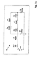
- FIG. 1A is an exemplary electrical schematic analogizing the acoustical network of a standard pressure or omni-directional microphone having a vent in the diaphragm.
- FIG. 1B is a frequency response curve for the standard pressure or omni-directional microphone of FIG. 1A.
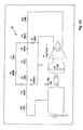
- FIG. 2A is an exemplary electrical schematic analogizing the acoustical network of a directional microphone having a vent in the diaphragm.
- FIG. 2B is a frequency response curve for the directional microphone of FIG. 2A and a directional microphone that lacks a vent in the diaphragm (i.e., a standard directional microphone).
- FIGS. 3A-3C are an embodiment of the present invention employing an external wind noise suppression channel.
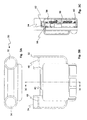
- FIGS. 4A-4C are another embodiment of the present invention employing an external wind noise suppression tube.
- FIGS. 5A-5B are yet another embodiment of the present invention employing an internal wind noise suppression tube.
- FIG. 6 is an exemplary electrical schematic analogizing the acoustical network of a directional microphone having an external or internal wind noise suppression tube/channel of the present invention.
- FIG. 7 is a frequency response curve that compares a standard directional microphone with a directional microphone that has an external or internal wind noise suppression tube of the present invention.
- FIG. 8A is an exemplary electrical schematic analogizing the acoustical network of a directional microphone having an external or internal wind noise suppression tube with a wind noise as an input source.
- FIG. 8B is a graph of the sound pressure levels of the wind noise source of FIG. 8A and a 74 dB SPL plane wave that represents conversational speech.
- FIG. 8C illustrates the output of a standard directional microphone that lacks the wind noise suppression tube of the present invention.
- FIG. 8D illustrates the output of a directional microphone having an external or internal wind noise suppression tube of the present invention.
- FIG. 9 illustrates the response shapes of various geometries of the wind noise suppression tube/channel by listing the acoustical resistance "R” and the inertance "L” of the tube.
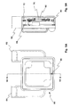
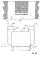
- FIG. 10 illustrates a listening device which includes a mounting plate molded to form a wind noise suppression conduit and a directional microphone.
- acoustical compliance is analogous to electrical capacitance
- acoustical inertance or mass
- acoustical resistance is analogous to electrical resistance.
- Several of the acoustical networks will be described as electrical networks with values placed on the components of the networks. It should be understood that the application of the present invention is not limited to only those values listed, but can be applied to directional microphones having various values for the acoustical resistances, acoustical compliances, and acoustical inertances of the components in their acoustical networks.
- FIG. 1A illustrates an electrical schematic that is analogous to the acoustical network 10 for a standard pressure microphone.
- R inf and L inf are the acoustical resistance of the input screen placed in a front inlet and the acoustical inertance of the air in the inlet, respectively, of the standard pressure microphone.
- R d , L d , and C d are the acoustical resistance, acoustical inertance, and acoustical compliance of the diaphragm within the microphone.
- the resistance, R d is the resistance to the sound wave impinging on the diaphragm.
- the inertance, L d relates to the mass of the diaphragm.
- the compliance, C d relates to the spring effect of the diaphragm.
- R v and L v are the acoustical resistance and inertance, respectively, of the vent in the diaphragm leading from the front volume to the back volume.
- the vent is placed in the diaphragm to equalize the pressure between the front and back volumes.
- C f and C r are the compliances of the front volume and the back (rear) volume, respectively. They represent the ability of the air to be compressed and expanded under pressure in the front and back volumes.
- V f represents the pressure from a sound source that would be entering the front volume.
- the values placed adjacent to each of these acoustical components in the network 10 are representative of typical values for a Model 100-Series microphone from Microtronic, the assignee of the present application.
- FIG. 1B is a frequency response curve of the microphone defined by the acoustical network 10 in FIG. 1A.
- the slope of the line is about 6 dB per octave.
- the microphone having the acoustical network 10 of FIG. 1A has a 6 dB per octave roll-off for low frequencies.
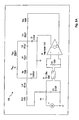
- FIG. 2A illustrates an electrical schematic that is analogous to the acoustical network 20 for a directional microphone that includes a vent in the diaphragm.
- Directional microphones are not usually constructed with a vent in the diaphragm, since there is no need for a vent to equalize the pressure due to the front and back volumes being opened to the ambient environment.
- the directional microphone represented by the acoustical network 20 includes a vent in the diaphragm to illustrate its effects.
- the vent is a tube having a very small diameter (e.g., 45 to 60 microns) and a very short length that is the thickness of the diaphragm.
- the vent is a highly resistive component but with a low inductance (i.e., inertance).
- All of the reference components in the acoustical network 20 shown in FIG. 2B are the same as in FIG. 1A, except that the R inr and L inr are the acoustical resistance of the screen in the back (rear) inlet and the inertance of the rear inlet, respectively, of the directional microphone.
- the primary purpose of the screens in the front and rear inlets is to provide a net internal time delay (i.e., a phase shift) to sounds entering their respective volumes.
- the internal time delay of a directional microphone is set such that a desired polar directivity pattern is obtained.
- the primary purpose of the screens in omni-directional microphones and pressure microphones is to dampen the peak in the frequency response.
- a time delay circuit which includes T 1 , R 7 (R 7 is the terminating impedance and is set equal to the characteristic impedance of the delay line T1 in order to simulate a uni-directional plane wave), and the amplifier having Vr as an output leading to the rear inlet, represents the time lag between the sound wave entering the front and rear inlets.
- an external time delay, TD of 26 microseconds is used in this directional microphone model and is a function of the distance between the front and back inlets.
- FIG. 2A is modeling a plane wave of conversational speech where there is no pressure imbalance.
- the lower portion of the circuit in FIG. 2A is the modeling of the sound inputs (V r and V f ) that are received in the front and rear inlets of a directional microphone having this type of acoustical network 20.
- FIG. 2B illustrates the frequency response curves for the acoustical network 20 in FIG. 2A, with and without the vent (i.e., with and without the upper branch having the acoustical resistance R v and inertance L v ).
- R v and L v acoustical resistance
- L v inertance
- the diaphragm vent with its resistance R v and impedance L v , causes a high impedance bypass path that, as a result, somewhat reduces the current through C d .
- the effect is a resistive voltage divider of the vent, in series with the total screen resistors, R inf and R inr . Since the vent resistance is normally much larger than the mechanical screens in the back and front inlets, the attenuation due to the vent is often negligible. Accordingly, a simple vent in the diaphragm of a directional microphone will not result in a decrease in the roll-off at low frequencies.
- FIGS. 3A-3C illustrate several views of a directional microphone employing an external wind noise suppression channel according to one embodiment of the present invention.
- a directional microphone 30 includes a front inlet 32 and a back inlet 34 that lead into a housing that includes a front volume 36 and a back volume 38, respectively.
- a diaphragm 39 divides the front volume 36 from the back volume 38.
- the diaphragm 39 is supported within the directional microphone 30 by a support structure 40 attached to the inside of the housing.
- An external C-shaped channel 42 extends between the front inlet 32 and the back inlet 34.
- the channel 42 has an internal opening 44 that acoustically connects the front inlet 32 and the back inlet 34.
- the rectangular internal opening 44 is defined on three sides by the C-shaped channel 42 and one side by the external surface of the housing 42.
- the intersections of the internal opening 44 and the inlets 32 and 34 are downstream from the screens 46 that are often placed within the inlets 32 and 34 to assist in developing the phase shift. It is these screens 46 that represent the R inf and R inr in the previous schematic of FIG. 2A.
- FIGS. 4A-4C illustrate a a directional microphone 50 according to another embodiment of the present invention.
- the directional microphone 50 includes a cylindrical tube 52 having an internal circular opening 54 connects the front inlet 32 and the back inlet 34.
- the theory of operation between the directional microphone 30 of FIGS. 3A-3C and the directional microphone 50 of FIGS. 4A-4C is the same, although the dimensions and shapes of the internal openings 44 and 54 are slightly different.
- the lengths of the channel 42 and the tube 52 are usually in the range of about 1 mm to about 6 mm, and the openings 44 and 45 have dimensions (diameters) that range from about 0.05 mm to about 0.5 mm.
- the front inlet 32 and the back inlet 34 could be moved relative to each other to accommodate a certain length that produces a desirable effect in the performance of the microphone.
- the channel 42 or tube 52 can be formed as an integral part of the front and back inlets 32 and 34.
- the assembly would then be a cap-like structure that fits onto the microphone.
- Such a structure could be molded of a plastic placed over the microphone housing and sealed along its periphery.
- the channel or tube could be an integral structure formed along an exterior wall of the housing between the inlets.
- FIGS. 5A and 5B illustrate a different embodiment of the present invention in which a directional microphone 60 includes an internal connection between a front volume 66 and a back volume 68 that receives sound from a front inlet 62 and a back inlet 64, respectively.
- the front volume 66 and the back volume 68 are separated by a diaphragm 70 that is mounted within the housing by a support frame 72.
- An internal hollow tube 80 is mounted in the support frame 72.
- the hollow tube 80 has a length of generally between 1 mm to 6 mm and an opening with a diameter of about 0.05 mm to about 0.5 mm.
- the invention contemplates supporting the hollow tube 80 with other structures such that the tube 80 may pierce the diaphragm and possibly the backplate. Further, the tube 80 can be integrally formed in the inner wall of the housing.
- one wind noise suppression tube or channel may be located outside the housing and another inside.
- tubes and channels are types of conduits.
- FIG. 6 is an electrical schematic of an acoustical network 90 of a directional microphone of the present invention and is similar to the schematic of FIG. 2A.
- the highly resistive vent has been replaced by the elongated tube (or channel) of the present invention, which introduces a much larger inductive element in the circuit (i.e., the increased acoustical inertance from the tube/channel) and a much smaller resistive element due to its larger diameter.
- the circuit now includes R wc and L wc , which are the resistance and inductance of a wind noise suppression channel/tube (“WC") that connects the front and back volumes of the directional microphone.
- the RL characteristics of the wind noise suppression channel/tube WC present, in essence, a high pass filter to the acoustical network 90.
- FIG. 7 illustrates the effects of a wind noise suppression channel/tube in the directional microphone at 0° and 180° angles of incidence of the sound wave.
- the inductive characteristics of a directional microphone according to the present invention brought about through the external channel 42 of FIG. 3C, the external tube 52 of FIG. 4C, or the internal tube 80 of FIG. 5B cause an increase in the slope of the curves, resulting in a 12 dB/octave roll-off at the low frequencies, instead of only the 6 dB/octave roll-off caused by the subtraction of time delayed signals (i.e., the principle of directivity in a directional microphone due to the screens).
- a directional microphone according to the present invention acts to suppress (and preferably cancel) these wind noises such that only the more desirable sounds are heard by the wearer of the hearing aid.
- FIG. 2B A comparison of FIG. 2B with FIG. 7 yields two noteworthy observations. First, the curves for the no-vent model in FIG. 2B and the curve for the no-WC model in FIG. 7 are identical, as would be expected. Second, the higher inductance from the wind noise suppression channel/tube substantially affects the shape of the curve.
- FIG. 8A is an electrical schematics representation of an acoustical network 100 that models the effects of a wind noise acting on the system where the wind noise introduces a pressure imbalance between the front and rear inlets.
- the components V F , R 6 , C 3 , R 7 , and V R have been fixed to values that would approximate the pressure imbalance inputs of a certain wind noise that is shown in FIG. 8B.
- the magnitude of V R is chosen to be half the magnitude of V F , which is provided by an assumption that one sound inlet of the microphone is midway between the origin of the wind turbulence and the second sound inlet.
- FIG. 6 models a sound input that has no pressure imbalance between the front and rear inlets
- FIG. 8A has introduced components that model a pressure imbalance associated with that sound input.
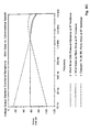
- FIG. 8B represents the two types of sound inputs for the model of the directional microphone conditions illustrated in the acoustical network 90 in FIG. 6 or the acoustical network 100 in FIG. 8A.
- the horizontal Plane Wave Source at 74 dB SPL is representative of conversational speech.
- the Wind Noise Source has a high SPL at the low frequencies and has been selected based on a paper which suggests a level of 98 dB SPL at 100 Hz for a wind with a velocity of 10 miles/hour. This paper titled, "Electronic Removal Of Outdoor Microphone Wind Noise" by Shust et al., was presented at the 136th Meeting of the Acoustical Society of America, in October of 1998, and is incorporated herein by reference in its entirety.
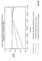
- FIGS. 8C and 8D illustrate the voltage outputs of a standard directional microphone (i.e., one that lacks R wc and L wc shown in the acoustical networks 90 and 100) and a wind-noise suppressed directional microphone of the present invention, respectively, for the input sound sources of FIG. 8B.
- a standard directional microphone i.e., one that lacks R wc and L wc shown in the acoustical networks 90 and 100
- a wind-noise suppressed directional microphone of the present invention respectively, for the input sound sources of FIG. 8B.
- Three curves are shown in FIGS. 8C and 8D.
- Curve 1 identified as "Constant 74 dB SPL Plane Wave at 0° Incidence," is representative of constant Conversational Speech at 74 dB SPL.
- Curve 3 is the most complete model for wind noise. Note that the curves do not represent frequency responses but, instead, output responses of a directional microphone as the source sound characteristics are being inputted into the directional microphone.
- Curves 1 and 3 in both FIGS. 8C and 8D remains unchanged, meaning that the directional microphone's output from a wind noise source with a pressure imbalance (Curve 3 in both FIGS. 8C and 8D) relative to that of conversational speech source (Curve 1 in both FIGS. 8C and 8D) is the same for a standard directional microphone as well as the directional microphone having the wind noise suppression feature according to the present invention.
- a difference between a wind noise suppressed and a standard directional microphone is the 12 dB/octave roll-off instead of a 6 dB/octave roll-off. Consequently, there is much less tendency for the microphone elements to overload because of the high output at low frequencies that is characteristic of wind noise.
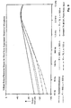
- FIG. 9 illustrates that different values of the acoustical resistance and inertance of wind noise suppression channels/tubes can result in different frequency response shapes.
- the input is simply a 74 dB SPL plane wave input.
- a standard directional microphone that lacks wind noise suppression channels/tubes is also illustrated for the sake of comparison. Accordingly, diameters and lengths of the wind noise suppression channels/tubes can be selected to achieve a particular output response.
- the internal surface structure of the wind noise suppression channels/tubes e.g., a roughened surface to create more resistance or a more elliptical or bubbled shape having a varying cross-sectional area along the length of the wind noise suppression channels/tubes
- R wc and L wc values can be altered to achieve desirable R wc and L wc values.
- a tube having a length of 5 mm and a diameter of 0.58 mm has an inductance of 300 mH CGS and a resistance of 340 Ohms CGS.
- a tube with half the length (i.e., 2.5 mm) and a diameter of 0.4 mm has an inductance of 100 mH CGS and a resistance of 680 Ohms CGS.
- the directional microphone according to the present invention preferably has lower sensitivity (i.e., a larger roll-off) for frequencies below about 500 Hz and, even more preferably, for frequencies below about 2.0 kHz.
- FIG. 10 illustrates a directional microphone 110 and a cutaway surface view of a faceplate or mounting plate 112 which includes a wind noise suppression conduit 114.
- the microphone 110 includes a front inlet 116, a back inlet 118, and a housing 120. When the housing 120 and the mounting plate 112 are positioned against each other, the front inlet 116 is connected to the back inlet 118 via the conduit 114.
- the shape and geometry of the conduit 114 is selected according to one or more of the parameters set forth above in order to achieve desired resistance and inductance values, R wc and L wc , respectively.
- the cross sectional shape of the conduit 114 may be circular or elliptical, C-shaped, or rectangular, and the shape may be constant or varied along the length of the conduit 114.
- the internal surface structure of the conduit 114 may be smooth or varied to create more resistance, for example.
- the conduit 114 is a hollow tube that connects the front inlet 116 and the back inlet 118 via the front conduit opening 122 and back conduit opening 124.
- the conduit 114 is a channel or groove formed on the surface of the mounting plate 112, and is closed by positioning a bottom surface of the microphone 110 over the conduit 114.
- the conduit 114 is formed in the mounting plate 112 such that one of the surfaces of the conduit 114 is defined by an outer surface 126 of the microphone 110.
- the microphone 110 does not include openings 122, 124, and the conduit 114 is positioned in the mounting plate 112 ahead of the front inlet 116 and back inlet 118.
- the directional microphone of the present invention is useful for all listening devices, including hearing aids.
- the audio signals from the directional microphone according to the present invention can be amplified by an amplifier and, subsequently, sent to a receiver that broadcasts an amplified acoustical signal to the user of the listening device.
Landscapes
- Health & Medical Sciences (AREA)
- Otolaryngology (AREA)
- Physics & Mathematics (AREA)
- Engineering & Computer Science (AREA)
- Acoustics & Sound (AREA)
- Signal Processing (AREA)
- Circuit For Audible Band Transducer (AREA)
- Headphones And Earphones (AREA)
- Obtaining Desirable Characteristics In Audible-Bandwidth Transducers (AREA)
Applications Claiming Priority (2)
| Application Number | Priority Date | Filing Date | Title |
|---|---|---|---|
| US26149301P | 2001-01-12 | 2001-01-12 | |
| US261493P | 2001-01-12 |
Publications (2)
| Publication Number | Publication Date |
|---|---|
| EP1229758A2 true EP1229758A2 (fr) | 2002-08-07 |
| EP1229758A3 EP1229758A3 (fr) | 2007-08-15 |
Family
ID=22993543
Family Applications (1)
| Application Number | Title | Priority Date | Filing Date |
|---|---|---|---|
| EP02075139A Withdrawn EP1229758A3 (fr) | 2001-01-12 | 2002-01-14 | Suppression du bruit de souffle dans un microphone directionnel |
Country Status (2)
| Country | Link |
|---|---|
| US (2) | US7260236B2 (fr) |
| EP (1) | EP1229758A3 (fr) |
Cited By (2)
| Publication number | Priority date | Publication date | Assignee | Title |
|---|---|---|---|---|
| US7876918B2 (en) | 2004-12-07 | 2011-01-25 | Phonak Ag | Method and device for processing an acoustic signal |
| CN1802039B (zh) * | 2004-09-20 | 2011-10-19 | 索尼昂荷兰有限公司 | 麦克风组件 |
Families Citing this family (19)
| Publication number | Priority date | Publication date | Assignee | Title |
|---|---|---|---|---|
| US7072482B2 (en) | 2002-09-06 | 2006-07-04 | Sonion Nederland B.V. | Microphone with improved sound inlet port |
| US7949522B2 (en) | 2003-02-21 | 2011-05-24 | Qnx Software Systems Co. | System for suppressing rain noise |
| US7895036B2 (en) * | 2003-02-21 | 2011-02-22 | Qnx Software Systems Co. | System for suppressing wind noise |
| US8326621B2 (en) | 2003-02-21 | 2012-12-04 | Qnx Software Systems Limited | Repetitive transient noise removal |
| US7725315B2 (en) * | 2003-02-21 | 2010-05-25 | Qnx Software Systems (Wavemakers), Inc. | Minimization of transient noises in a voice signal |
| US7885420B2 (en) * | 2003-02-21 | 2011-02-08 | Qnx Software Systems Co. | Wind noise suppression system |
| US8073689B2 (en) * | 2003-02-21 | 2011-12-06 | Qnx Software Systems Co. | Repetitive transient noise removal |
| US8271279B2 (en) | 2003-02-21 | 2012-09-18 | Qnx Software Systems Limited | Signature noise removal |
| US7162041B2 (en) * | 2003-09-30 | 2007-01-09 | Etymotic Research, Inc. | Noise canceling microphone with acoustically tuned ports |
| US7346179B1 (en) * | 2003-12-31 | 2008-03-18 | Plantronics, Inc. | Microphone with low frequency noise shunt |
| WO2008124786A2 (fr) * | 2007-04-09 | 2008-10-16 | Personics Holdings Inc. | Système d'enregistrement permanent de coiffure |
| US8144906B2 (en) * | 2008-05-21 | 2012-03-27 | Akustica, Inc. | Wind immune microphone |
| CN103380629B (zh) | 2011-02-25 | 2017-06-13 | 诺基亚技术有限公司 | 换能器设备 |
| CN103323619A (zh) * | 2012-03-20 | 2013-09-25 | 富泰华工业(深圳)有限公司 | 风向检测系统、风向检测方法及使用该风向检测系统的电子设备 |
| JP5931566B2 (ja) * | 2012-04-26 | 2016-06-08 | 株式会社オーディオテクニカ | 単一指向性マイクロホン |
| US10397711B2 (en) * | 2015-09-24 | 2019-08-27 | Gn Hearing A/S | Method of determining objective perceptual quantities of noisy speech signals |
| CN105979438A (zh) * | 2016-05-30 | 2016-09-28 | 歌尔股份有限公司 | 一种防风噪麦克风单体和耳机 |
| US12200429B2 (en) | 2022-04-21 | 2025-01-14 | Meta Platforms Technologies, Llc | Manifold architecture for wind noise abatement |
| CN114974200B (zh) * | 2022-07-13 | 2023-02-03 | 恩平市菲玛特电子科技有限公司 | 基于物联网的麦克风语音交互管理系统及方法 |
Family Cites Families (6)
| Publication number | Priority date | Publication date | Assignee | Title |
|---|---|---|---|---|
| US3836732A (en) * | 1972-09-07 | 1974-09-17 | Audivox Inc | Hearing aid having selectable directional characteristics |
| US5204907A (en) * | 1991-05-28 | 1993-04-20 | Motorola, Inc. | Noise cancelling microphone and boot mounting arrangement |
| US5878147A (en) * | 1996-12-31 | 1999-03-02 | Etymotic Research, Inc. | Directional microphone assembly |
| US6151399A (en) * | 1996-12-31 | 2000-11-21 | Etymotic Research, Inc. | Directional microphone system providing for ease of assembly and disassembly |
| WO2000002419A1 (fr) * | 1998-07-01 | 2000-01-13 | Resound Corporation | Membrane protective exterieure pour microphone |
| US6681021B1 (en) | 1998-12-18 | 2004-01-20 | Siemens Hearing Instruments, Inc. | Directional ITE hearing aid using dual-input microphone |
-
2002
- 2002-01-09 US US10/042,860 patent/US7260236B2/en not_active Expired - Fee Related
- 2002-01-14 EP EP02075139A patent/EP1229758A3/fr not_active Withdrawn
-
2006
- 2006-09-28 US US11/528,802 patent/US20070019835A1/en not_active Abandoned
Cited By (2)
| Publication number | Priority date | Publication date | Assignee | Title |
|---|---|---|---|---|
| CN1802039B (zh) * | 2004-09-20 | 2011-10-19 | 索尼昂荷兰有限公司 | 麦克风组件 |
| US7876918B2 (en) | 2004-12-07 | 2011-01-25 | Phonak Ag | Method and device for processing an acoustic signal |
Also Published As
| Publication number | Publication date |
|---|---|
| US20070019835A1 (en) | 2007-01-25 |
| EP1229758A3 (fr) | 2007-08-15 |
| US7260236B2 (en) | 2007-08-21 |
| US20020094101A1 (en) | 2002-07-18 |
Similar Documents
| Publication | Publication Date | Title |
|---|---|---|
| US7260236B2 (en) | Wind noise suppression in directional microphones | |
| US5282245A (en) | Tubular bi-directional microphone with flared entries | |
| US9609411B2 (en) | Microphone environmental protection device | |
| US4852177A (en) | High fidelity earphone and hearing aid | |
| US4410770A (en) | Directional microphone | |
| US8254616B2 (en) | Microphone with a low frequency noise shunt | |
| US10771904B2 (en) | Directional MEMS microphone with correction circuitry | |
| US10805739B2 (en) | Non-occluding feedback-resistant hearing device | |
| JPH0965478A (ja) | 指向性マイクロホン合成体 | |
| CN106454576A (zh) | 主动降噪入耳式耳机 | |
| US12363473B2 (en) | Audio systems, devices, mems microphones, and methods thereof | |
| US6700985B1 (en) | Ear level noise rejection voice pickup method and apparatus | |
| GB2321819A (en) | Boundary-layer microphone with sound tunnel running underneath the plate surface | |
| CN206024053U (zh) | 主动降噪入耳式耳机 | |
| GB2453434A (en) | Noise reducing module for earphones | |
| KR101691373B1 (ko) | 단일 지향성 멤스 마이크로폰 구조체 | |
| CN114846814A (zh) | 具有声音后腔室通风口的耳机 | |
| JPH0630490A (ja) | イヤーセット型送受話器 | |
| CN116193339B (zh) | 一种送话器装置 | |
| Elko et al. | An adaptive close-talking microphone array | |
| US11297411B2 (en) | Microphone units with multiple openings | |
| CN1998263A (zh) | 具有声音调整端口的噪声消除话筒 | |
| KR20150018926A (ko) | 스피커용 가변 인클로우져 | |
| KR20150017851A (ko) | 스피커용 가변 용적 인클로우져 |
Legal Events
| Date | Code | Title | Description |
|---|---|---|---|
| PUAI | Public reference made under article 153(3) epc to a published international application that has entered the european phase |
Free format text: ORIGINAL CODE: 0009012 |
|
| AK | Designated contracting states |
Kind code of ref document: A2 Designated state(s): AT BE CH CY DE DK ES FI FR GB GR IE IT LI LU MC NL PT SE TR |
|
| AX | Request for extension of the european patent |
Free format text: AL;LT;LV;MK;RO;SI |
|
| RAP1 | Party data changed (applicant data changed or rights of an application transferred) |
Owner name: SONIONMICROTRONIC NETHERLAND B.V. |
|
| RAP1 | Party data changed (applicant data changed or rights of an application transferred) |
Owner name: SONIONMICROTRONIC NEDERLAND B.V. |
|
| PUAL | Search report despatched |
Free format text: ORIGINAL CODE: 0009013 |
|
| AK | Designated contracting states |
Kind code of ref document: A3 Designated state(s): AT BE CH CY DE DK ES FI FR GB GR IE IT LI LU MC NL PT SE TR |
|
| AX | Request for extension of the european patent |
Extension state: AL LT LV MK RO SI |
|
| 17P | Request for examination filed |
Effective date: 20080215 |
|
| AKX | Designation fees paid |
Designated state(s): AT BE CH CY DE DK ES FI FR GB GR IE IT LI LU MC NL PT SE TR |
|
| 17Q | First examination report despatched |
Effective date: 20080612 |
|
| STAA | Information on the status of an ep patent application or granted ep patent |
Free format text: STATUS: THE APPLICATION IS DEEMED TO BE WITHDRAWN |
|
| 18D | Application deemed to be withdrawn |
Effective date: 20081023 |