EP1229773A2 - Passiver Verteiler zum Verbinden von elektrischen Geräten wie Aktoren und/oder Sensoren - Google Patents
Passiver Verteiler zum Verbinden von elektrischen Geräten wie Aktoren und/oder Sensoren Download PDFInfo
- Publication number
- EP1229773A2 EP1229773A2 EP01129579A EP01129579A EP1229773A2 EP 1229773 A2 EP1229773 A2 EP 1229773A2 EP 01129579 A EP01129579 A EP 01129579A EP 01129579 A EP01129579 A EP 01129579A EP 1229773 A2 EP1229773 A2 EP 1229773A2
- Authority
- EP
- European Patent Office
- Prior art keywords
- sensors
- distributor
- actuators
- electronic circuit
- electrical device
- Prior art date
- Legal status (The legal status is an assumption and is not a legal conclusion. Google has not performed a legal analysis and makes no representation as to the accuracy of the status listed.)
- Withdrawn
Links
- 238000007781 pre-processing Methods 0.000 claims description 4
- 230000004888 barrier function Effects 0.000 description 1
- 230000005540 biological transmission Effects 0.000 description 1
- 238000009420 retrofitting Methods 0.000 description 1
Images

Classifications
-
- H—ELECTRICITY
- H05—ELECTRIC TECHNIQUES NOT OTHERWISE PROVIDED FOR
- H05K—PRINTED CIRCUITS; CASINGS OR CONSTRUCTIONAL DETAILS OF ELECTRIC APPARATUS; MANUFACTURE OF ASSEMBLAGES OF ELECTRICAL COMPONENTS
- H05K7/00—Constructional details common to different types of electric apparatus
- H05K7/14—Mounting supporting structure in casing or on frame or rack
- H05K7/1462—Mounting supporting structure in casing or on frame or rack for programmable logic controllers [PLC] for automation or industrial process control
- H05K7/1468—Mechanical features of input/output (I/O) modules
- H05K7/1472—Bus coupling modules, e.g. bus distribution modules
-
- H—ELECTRICITY
- H01—ELECTRIC ELEMENTS
- H01R—ELECTRICALLY-CONDUCTIVE CONNECTIONS; STRUCTURAL ASSOCIATIONS OF A PLURALITY OF MUTUALLY-INSULATED ELECTRICAL CONNECTING ELEMENTS; COUPLING DEVICES; CURRENT COLLECTORS
- H01R25/00—Coupling parts adapted for simultaneous co-operation with two or more identical counterparts, e.g. for distributing energy to two or more circuits
- H01R25/003—Coupling parts adapted for simultaneous co-operation with two or more identical counterparts, e.g. for distributing energy to two or more circuits the coupling part being secured only to wires or cables
Definitions
- a distributor of the generic type is for example from EP 0 909 121 or also known from German utility model DE 299 09 204.
- Such distributors have a plurality of slots.
- the sockets of the connections are usually connected in parallel via a circuit board with e.g. two connector strips connected, which are arranged in a connection housing. From here the sensor data is forwarded e.g. to the PC or to the PLC.
- the connector strips are used for passive distributors e.g. four, six or eight lines to the processing PLC. This then requires e.g. also the assignment of four, six or eight inputs. Such inputs are relatively expensive. Currently, the cost is one Entrance often up to 30, - DM.
- the invention is therefore concerned with the task of the necessary number of connecting lines and the number of inputs to be assigned to the control unit to reduce.
- the passive distributor then has an electronic circuit for preprocessing, in particular to link the data received from the sensors before forwarding them to the external electrical device.
- the (additional) electronic circuit has components for the logical connection of the sensor signals (e.g. AND, NAND, NOR ...) on what the signals coming from the electrical device in a simple manner logically preprocess and link the linked signal to the control unit hand off.
- the sensor signals e.g. AND, NAND, NOR
- the electronic circuit is designed to be pluggable, preferably on a circuit board.
- a particular advantage is here the possibility of retrofitting the electronic circuit. In this way can also retrofit passive distributors with an electronic circuit Preprocessing of the sensor signals.
- the circuit board is preferably space-saving and practical to handle in a housing the distributor arranged.
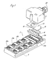
- FIG. 1 shows a distributor 2 for connecting actuators and / or sensors S1, S2 (see Fig. 2) with at least one external electrical device.
- This external device can be, for example, a control unit such as a PC or a PLC.
- the distributor 2 has a connection block 4 designed for connection area Connection of the actuators and / or sensors to the distributor 2 and one to the connection block 4 attachable connection housing 6 as a connection area for connection at least a connecting cable 8 for the supply of the actuators and / or sensors or to forward the actuator / sensor signals between the PLC and the distributor 2 on.
- connections 10 are with two connection strips 12 connected in the connector housing 6.
- a circuit board 16 can be contacted indirectly via interposed connector strips 14 be provided with (see FIG. 2) logic modules 22 which form an electronic circuit 24 for preprocessing those coming from the actuators and / or sensors Signals are summarized. From the circuit board 16 are on the connector 18 only a few data lines through the opening 20 of the connection housing 6 to the PLC. Depending on the logical task to be solved can provide various circuit boards 16 with corresponding components become.
- circuit board 16 with the electronic circuit 24 easily replaceable pluggable is and that commercially available passive distributors with any customized additional circuits on site or shortly before delivery can be retrofitted.
Landscapes
- Engineering & Computer Science (AREA)
- Automation & Control Theory (AREA)
- Microelectronics & Electronic Packaging (AREA)
- Programmable Controllers (AREA)
- Connections Arranged To Contact A Plurality Of Conductors (AREA)
Abstract
Description
- wenigstens einen ersten Anschlußbereich zum Anschluß der Aktoren und/oder Sensoren an den Verteiler und
- einen zweiten Anschlußbereich, der vorzugsweise an den ersten Anschlußbereich angrenzt und der zum Anschluß wenigstens eines Anschlußkabels für die Versorgung der Aktoren und/oder Sensoren und/oder zur Weiterleitung der Aktor-/Sensorsignale- insbesondere Logikinformationen - zwischen den Aktoren/Sensoren und dem externen elektrischen Gerät vorgesehen ist.
- Figur 1
- eine Sprengansicht eines erfindungsgemäßen passiven Verteilers;
- Figur 2
- eine schematische Ansicht eines passiven Verteilers nebst daran angeschlossenen Sensoren und der an den Verteiler angeschlossenen Steuerungseinheit.
- Verteiler
- 2
- Anschlußblock
- 4
- Anschlußgehäuse
- 6
- Anschlußkabel
- 8
- Anschlüsse
- 10a, 10b, ...
- Anschlußleisten
- 12a, 12b
- Steckerleisten
- 14
- Leiterplatte
- 16
- Anschlußelement
- 18
- Öffnung
- 20
- Logikbausteine
- 22
- Elektronikschaltung
- 24
- Sensoren
- S1, S2
Claims (5)
- Passiver Verteiler zum Verbinden von Aktoren und/oder Sensoren (S1, S2) mit wenigstens einem elektrischen Gerät, insbesondere mit einer Steuerungseinheit wie einem PC oder einer SPS, wobei der Verteiler folgendes aufweist:gekennzeichnet durchwenigstens einen ersten Anschlußbereich (4) zum Anschluß der Aktoren und/oder Sensoren an den Verteiler (2), undeinen zweiten Anschlußbereich, der vorzugsweise an den ersten Anschlußbereich (4) angrenzt und der zum Anschluß wenigstens eines Anschlußkabels (8) für die Versorgung der Aktoren und/oder Sensoren und/oder zur Weiterleitung der Aktor-/Sensorsignale- insbesondere Logikinformationen - zwischen den Aktoren/Sensoren und dem externen elektrischen Gerät vorgesehen ist,eine Elektronikschaltung (24) zur Vorverarbeitung, insbesondere zur Verknüpfung der von den Sensoren (S1, S2) eingehenden Daten vor deren Weiterleitung zum externen elektrischen Gerät (SPS, PC).
- Verteiler nach Anspruch 1, dadurch gekennzeichnet, daß die Elektronikschaltung (24) steckbar ausgebildet ist.
- Verteiler nach Anspruch 1 oder 2, dadurch gekennzeichnet, daß die Elektronikschaltung (24) Bauelemente (22) zur logischen Verknüpfung der Sensorsignale aufweist.
- Verteiler nach einem der vorstehenden Ansprüche, dadurch gekennzeichnet, daß die Elektronikschaltung (24) auf einer Leiterplatte (16) angeordnet ist.
- Verteiler nach einem der vorstehenden Ansprüche, dadurch gekennzeichnet, daß die Leiterplatte (6) in einem Gehäuse (6) des Verteilers angeordnet ist.
Applications Claiming Priority (2)
| Application Number | Priority Date | Filing Date | Title |
|---|---|---|---|
| DE20102038U | 2001-02-05 | ||
| DE20102038U DE20102038U1 (de) | 2001-02-05 | 2001-02-05 | Passiver Verteiler zum Verbinden von elektrischen Geräten wie Aktoren und/oder Sensoren |
Publications (2)
| Publication Number | Publication Date |
|---|---|
| EP1229773A2 true EP1229773A2 (de) | 2002-08-07 |
| EP1229773A3 EP1229773A3 (de) | 2005-01-05 |
Family
ID=7952587
Family Applications (1)
| Application Number | Title | Priority Date | Filing Date |
|---|---|---|---|
| EP01129579A Withdrawn EP1229773A3 (de) | 2001-02-05 | 2001-12-12 | Passiver Verteiler zum Verbinden von elektrischen Geräten wie Aktoren und/oder Sensoren |
Country Status (2)
| Country | Link |
|---|---|
| EP (1) | EP1229773A3 (de) |
| DE (1) | DE20102038U1 (de) |
Families Citing this family (3)
| Publication number | Priority date | Publication date | Assignee | Title |
|---|---|---|---|---|
| DE20211002U1 (de) * | 2002-07-19 | 2003-12-04 | Weidmüller Interface Gmbh & Co. | Modul für ein elektrisches Gerät, insbesondere Feldbusmodul |
| DE102008053920A1 (de) * | 2008-10-30 | 2010-05-06 | Endress + Hauser Conducta Gesellschaft für Mess- und Regeltechnik mbH + Co. KG | Verteilermodul bzw. damit gebildetes Messsystem |
| WO2020043323A1 (de) * | 2018-08-27 | 2020-03-05 | Sew-Eurodrive Gmbh & Co. Kg | Umrichteranordnung und verfahren zum betreiben einer umrichteranordnung |
Citations (3)
| Publication number | Priority date | Publication date | Assignee | Title |
|---|---|---|---|---|
| DE19616551A1 (de) | 1996-04-25 | 1997-10-30 | Siemens Ag | Modulares, baugruppenweise erweiterbares Peripheriegerät mit selbsttragendem Aufbau |
| EP0909121A2 (de) | 1997-10-06 | 1999-04-14 | PHOENIX CONTACT GmbH & Co. | Elektronisches Ein-/Ausgabemodul |
| DE29909204U1 (de) | 1999-05-28 | 2000-10-05 | Weidmüller Interface GmbH & Co., 32758 Detmold | Verteiler zum Verbinden von Aktoren und/oder Sensoren |
Family Cites Families (5)
| Publication number | Priority date | Publication date | Assignee | Title |
|---|---|---|---|---|
| DE4412270C2 (de) * | 1994-04-09 | 1996-02-01 | Murrelektronik Ag | Bus-System |
| DE19716137C1 (de) * | 1997-04-17 | 1998-10-22 | Siemens Ag | Modul zum Anschluß von Aktoren und/oder Sensoren |
| DE19808343A1 (de) * | 1998-02-27 | 1999-09-09 | Siemens Ag | Vorrichtung zur Peripherieansteuerung |
| US6364670B1 (en) * | 1998-11-18 | 2002-04-02 | Robert Bosch Corporation | Junction box having function electronics |
| DE19855869C1 (de) * | 1998-12-03 | 2000-05-18 | Schmersal K A Gmbh & Co | Feldbusanschlußeinrichtung |
-
2001
- 2001-02-05 DE DE20102038U patent/DE20102038U1/de not_active Expired - Lifetime
- 2001-12-12 EP EP01129579A patent/EP1229773A3/de not_active Withdrawn
Patent Citations (3)
| Publication number | Priority date | Publication date | Assignee | Title |
|---|---|---|---|---|
| DE19616551A1 (de) | 1996-04-25 | 1997-10-30 | Siemens Ag | Modulares, baugruppenweise erweiterbares Peripheriegerät mit selbsttragendem Aufbau |
| EP0909121A2 (de) | 1997-10-06 | 1999-04-14 | PHOENIX CONTACT GmbH & Co. | Elektronisches Ein-/Ausgabemodul |
| DE29909204U1 (de) | 1999-05-28 | 2000-10-05 | Weidmüller Interface GmbH & Co., 32758 Detmold | Verteiler zum Verbinden von Aktoren und/oder Sensoren |
Also Published As
| Publication number | Publication date |
|---|---|
| DE20102038U1 (de) | 2002-06-27 |
| EP1229773A3 (de) | 2005-01-05 |
Similar Documents
| Publication | Publication Date | Title |
|---|---|---|
| EP0712267B1 (de) | Modulare Steuerungsanlage mit integriertem Feldbusanschluss | |
| EP1174781B1 (de) | Einrichtung zur Signalübertragung | |
| DE3701554A1 (de) | Maschinenanlage mit mehreren aktoren | |
| DE102008058090A1 (de) | Ein-/Ausgabemodul für ein Automatisierungsgerät | |
| DE10330916A1 (de) | Vorrichtung und Verfahren zum automatisierten Steuern eines Betriebsablaufs bei einer technischen Anlage | |
| EP1038354B1 (de) | Schaltungsanordnung zur überwachung des fehlerfreien und/oder zur erkennung eines fehlerbehafteten zustands einer anlage | |
| DE69305383T2 (de) | Sensorverbindungssystem | |
| DE4106601C2 (de) | Verbindungssystem für Kabel in eigensicheren Industrie-Schalttafeln | |
| EP2434355A1 (de) | Not-Aus-Modul-Anordnung | |
| EP2258153B1 (de) | Elektrisches baukastenmodulsystem mit einem variabel einsetzbaren feldbusmodul | |
| DE4323440A1 (de) | Elektronisches Gerät, insbesondere Automatisierungsgerät | |
| EP1711717B1 (de) | Druckluftwartungsvorrichtung | |
| EP0068482A1 (de) | Steuerungssystem, insbesondere für automatische Fertigungsanlagen | |
| EP0740082A1 (de) | Modularer elektrischer Teil für einen Ventilblock | |
| DE212012000249U1 (de) | Vorrichtung zum eigensicheren Versorgen, Ansteuern und/oder Auswerten von Feldgeräten im explosionsgeschützten Bereich | |
| EP1229773A2 (de) | Passiver Verteiler zum Verbinden von elektrischen Geräten wie Aktoren und/oder Sensoren | |
| DE102018130342A1 (de) | Schaltgeräteanordnung | |
| EP2369694B1 (de) | Anschlussvorrichtung und Automatisierungsgerät | |
| EP0809361B1 (de) | Elektronisches Schaltgerät und Schaltungsanordnung zur Überwachung einer Anlage | |
| WO2005054966A1 (de) | Eingensichere datenübertragungseinrichtung | |
| DE10163393B4 (de) | Anschlusselement für einen Bus | |
| EP0888707B1 (de) | Baugruppe mit einer schaltungsanordnung | |
| DE29610157U1 (de) | Mehrfachsensor | |
| EP3660603B1 (de) | Busfähiges aneinanderreihbares funktionsmodul | |
| EP0707249A2 (de) | Einrichtung zur Steuerung von mechanischen oder elektromechanischen Stellgliedern |
Legal Events
| Date | Code | Title | Description |
|---|---|---|---|
| PUAI | Public reference made under article 153(3) epc to a published international application that has entered the european phase |
Free format text: ORIGINAL CODE: 0009012 |
|
| AK | Designated contracting states |
Kind code of ref document: A2 Designated state(s): AT BE CH CY DE DK ES FI FR GB GR IE IT LI LU MC NL PT SE TR |
|
| AX | Request for extension of the european patent |
Free format text: AL;LT;LV;MK;RO;SI |
|
| PUAL | Search report despatched |
Free format text: ORIGINAL CODE: 0009013 |
|
| AK | Designated contracting states |
Kind code of ref document: A3 Designated state(s): AT BE CH CY DE DK ES FI FR GB GR IE IT LI LU MC NL PT SE TR |
|
| AX | Request for extension of the european patent |
Extension state: AL LT LV MK RO SI |
|
| 17P | Request for examination filed |
Effective date: 20050125 |
|
| AKX | Designation fees paid |
Designated state(s): AT BE CH CY DE DK ES FI FR GB GR IE IT LI LU MC NL PT SE TR |
|
| 17Q | First examination report despatched |
Effective date: 20090610 |
|
| STAA | Information on the status of an ep patent application or granted ep patent |
Free format text: STATUS: THE APPLICATION IS DEEMED TO BE WITHDRAWN |
|
| 18D | Application deemed to be withdrawn |
Effective date: 20140821 |