EP1229779B1 - Querförderschnecke für einen mäh- oder maiserntevorsatz - Google Patents
Querförderschnecke für einen mäh- oder maiserntevorsatz Download PDFInfo
- Publication number
- EP1229779B1 EP1229779B1 EP00971335A EP00971335A EP1229779B1 EP 1229779 B1 EP1229779 B1 EP 1229779B1 EP 00971335 A EP00971335 A EP 00971335A EP 00971335 A EP00971335 A EP 00971335A EP 1229779 B1 EP1229779 B1 EP 1229779B1
- Authority
- EP
- European Patent Office
- Prior art keywords
- screw
- main body
- transverse conveyor
- implement according
- corn harvesting
- Prior art date
- Legal status (The legal status is an assumption and is not a legal conclusion. Google has not performed a legal analysis and makes no representation as to the accuracy of the status listed.)
- Revoked
Links
- 238000003306 harvesting Methods 0.000 title claims description 28
- 240000008042 Zea mays Species 0.000 title claims description 26
- 235000002017 Zea mays subsp mays Nutrition 0.000 title claims description 26
- 235000016383 Zea mays subsp huehuetenangensis Nutrition 0.000 title description 2
- 235000009973 maize Nutrition 0.000 title description 2
- 230000010006 flight Effects 0.000 claims description 36
- 235000005824 Zea mays ssp. parviglumis Nutrition 0.000 claims description 24
- 235000005822 corn Nutrition 0.000 claims description 24
- 230000007423 decrease Effects 0.000 claims description 4
- 210000000056 organ Anatomy 0.000 description 19
- 238000011144 upstream manufacturing Methods 0.000 description 7
- 241000237858 Gastropoda Species 0.000 description 5
- 238000000034 method Methods 0.000 description 2
- 206010010774 Constipation Diseases 0.000 description 1
- 238000009825 accumulation Methods 0.000 description 1
- 238000012272 crop production Methods 0.000 description 1
- 230000001419 dependent effect Effects 0.000 description 1
- 230000000694 effects Effects 0.000 description 1
- 230000033001 locomotion Effects 0.000 description 1
- 238000004519 manufacturing process Methods 0.000 description 1
Images



Classifications
-
- A—HUMAN NECESSITIES
- A01—AGRICULTURE; FORESTRY; ANIMAL HUSBANDRY; HUNTING; TRAPPING; FISHING
- A01D—HARVESTING; MOWING
- A01D61/00—Elevators or conveyors for binders or combines
- A01D61/008—Elevators or conveyors for binders or combines for longitudinal conveying, especially for combines
Definitions
- the invention relates to a cross auger for a mowing or corn harvesting attachment according to the Preamble of claim 1.
- DE-A-195 23 255 discloses a corn harvesting attachment of the same genus, the cross-conveyor element of which is designed as a cross-conveyor screw having a cylindrical base body, the base body of which is rotated in sections by counter-pitch and constant-height screw flights.
- the cross conveyor is assigned a plurality of cutting and conveying rotors which rotate around vertical axes and which separate the crop in the working area from the remaining stalks in the ground and remove it from the working area.
- the cutting and conveyor rotors in the rear area are also assigned clearers rotating around vertical axes, which move the stalky crop out of the cutting and conveyor rotors and either directly to the cross conveyor or the distance between the scraper and the cross conveyor feed bridging intermediate conveyor cones. Due to the fact that the screw flights of the cross conveyor have a constant height, the arrangement of the cutting and conveyor rotors as well as the scraper and intermediate conveyor cone to the cross conveyor with different distances from the screw flights seen in the direction of travel, differently sized free spaces are formed between the cross conveyor and the rear area of the individual work organs out.
- the invention is therefore based on the object of a cross conveyor for a mowing or Form the corn header so that between the driving elements of the Cross conveyor and the upstream work organs give them little freedom, so that regardless of the crop throughput always a safe acceptance of the crop by Driving elements of the cross conveyor is guaranteed and the promotion of the crop low-friction and thus minimized wear due to the cross conveyor.
- the task is performed by a cross screw conveyor for a mowing or Corn harvesting header solved with the characterizing features of claim 1.
- the radially outer edges of the worm threads of the base body itself describe an envelope surface that changes at least partially in cross section Conveyor screw shape reached, depending on the cross-sectional area Enlargement or reduction of the good catchment area and that between the Helical worm gears and material conveying spaces forming the basic body.
- the distance of the worm threads describing the envelope surface to the work organs upstream of them are changed, so that always a safe acceptance of the Harvest crops are guaranteed by the augers.
- the size of the Gutierraum to be adapted to the amount of crop to be promoted by them low-friction and therefore wear-minimized crop transport in the field of To reach the cross conveyor.
- the ones encircling the base body can Worms form an enveloping surface that corresponds to the outer contour of the rear area of the follows the worm gear upstream working organs with a small distance. In this way form between the worm threads of the cross conveyor screw and the upstream ones Working organs only little free space, which is always independent of the crop throughput Capture the harvested crop located in these open spaces through the worm gear Enable cross conveyor screw.
- their outer Dimensions and their distance from the cross conveyor screw, as seen in the direction of travel can be Envelope surface to ensure only a small distance between the rear area the working elements and the transverse screw conveyor have a conical or undulating shape, wherein the envelope surface diameter in a conical shape from the outside in or conversely, can increase or decrease. If the envelope surface diameter increases inwards also ensures that the increasing amount of crop in larger crop production areas is transported with low friction and wear and in the central area of the cross conveyor screw due to the larger diameter, subsequent work organs can be fed quickly.
- the manufacturing outlay can be reduced the base body be cylindrical, in the simplest case as a cylinder tube, and only that In some areas, screw flights have different heights, so that according to the invention one envelope surface at least partially changing its cross section.
- the cross-conveyor screw In order to fluctuate in the thickness of the screw conveyor to be transported Avoiding the crop mat can be the basic body in a further advantageous embodiment the cross-conveyor screw have different cross sections in some areas, the Worms run around the basic body at a constant height. In this way they form Good transport spaces of constant height between the worm threads of the cross conveyor screw from the crop mat formed from substantially upright crop stalks so even that there is a crop flow of the same thickness with low Circulating movements between the crop stems.
- the change in the shape of the envelope surface can also only restrict to the end areas of the cross conveyor that are critical for the transfer of goods, so that a safe acceptance and removal of the Harvested crop is guaranteed by the cross conveyor, taking the Harvested crops through the work organs upstream of the cross conveyor in these end areas is avoided.
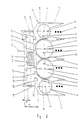
- a mowing and corn harvesting attachment 1 is shown schematically, which in its Front area in a manner known per se from compartments 2 to approximately vertical Axes 3 according to the arrow directions 5-8 revolving cutting and conveying rotors 4 which harvest the stalky crop 9 and along any webs 10 in the Promote the rear area of the cutting and conveyor rotors 4.
- Cross conveyor screw 11 assigned, which has a cylindrical base body 12, the centrally arranged transfer area 14 provided with conveyor webs 13 worm threads 15 having side areas are assigned.
- the worm threads 15 arranged on the right and left sides of the transfer area 14 opposite slopes on.
- the worm threads 15 supplied crop in a known and therefore not shown manner from the Conveyor webs 13 of the base body 12 are detected and subsequent, not shown Work organs of the carrier vehicle 16 indicated only schematically supplied.
- the height H of Worm flights 20 above the base body 12 in the direction of the central transfer area 14 remove so that those described by the outer edges 21 of the screw flights 20 Envelope surfaces 22 according to the invention are arranged at a short distance from the working members 4.
- the outer edges 21 of the worm threads 20 describe thus conical envelope surfaces 22, the envelope surface diameter D in the direction of the center Transfer area 14 decreases.
- the cutting and conveying rotors 4 corresponding to FIG. 3 in the rear area around the vertical axes 23 clearers 24 be assigned to the crop 9 located in the conveyor pockets 25 from these move out and feed a transverse screw 11 according to the invention.
- the scrapers 24 can have further intermediate conveyor elements 25 be assigned, which take over the crop 9 and feed it to the cross conveyor screw 11.
- Work organs 4, 24, 25 funding webs 26 can be assigned, the emergence of the Prevent crop stem 9 from the working organs 4, 24, 25.
- the height H of the screw flights 27 changes in such an embodiment over the base body 12 in such a way that the outer edges 28 of the screw flights 27th describe wavy envelope surfaces 29.
- the base body 12 of the Cross-conveyor screws 11 have a cylindrical shape and the height H of the screw flights 15, 20, 27 depending on the geometry and the arrangement of the working elements 4, 10, 24, 25, 26 changes, have the worm threads 15, 20, 27 and the base body 12 formed good transport rooms 30 different sizes, which sometimes have to be reinforced Circulation processes between the crop stems 9 located in the crop transport spaces 30 lead, especially when the height H of the screw flights 15, 20, 27 decreases sharply, so that the goods transport space 30 is significantly reduced.
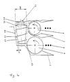
- the remedy creating, in a further advantageous embodiment, the cone-like or wave-like Shape of the envelope surfaces 19, 22, 29 can be achieved in that the respective base body 12, 31st is conical or wave-shaped, with only one conical in FIG.
- Base body 31 is shown, and those surrounding the respective base body 31 Worms 32 have a constant height H, so that the resulting good transport spaces 33 all have the same height. In this way, the circulation processes between the Crop stalks 9 of a crop transport space 33 due to changes in height of the Good transport space 33 avoided, which ultimately leads to a reduction in the drive of the Transverse screw conveyor 11 leads necessary energy requirements.
- the base body 31 is as in FIG 4 shown, conical in such a way that the diameter of the base body 31 in Direction of the central transfer area 14 increases, is a simple design Large diameter DD of the passage area 14 reached, so that the downstream Work organs to be handed over the crop quantity at a higher speed, minimizing congestion can be removed.
- cross screw 11 according to the invention is not in illustrated manner can also be designed so that both the cross section of the Base body 12, 31 and the height of the screw flights 15, 20, 27, 32 can change by achieve effects described.
Landscapes
- Life Sciences & Earth Sciences (AREA)
- Environmental Sciences (AREA)
- Screw Conveyors (AREA)
- Harvester Elements (AREA)
Description
Aufgrund dessen, daß die in der DE-OS 195 23 255 offenbarte Querförderschnecke von einem zylindrischen Grundkörper und diesen mit konstanter Höhe umlaufenden Schneckengängen gebildet wird, sind die von den Schneckengängen und dem Grundkörper begrenzten Gutförderräume und die erreichbare Gutgeschwindigkeit im Bereich der Querförderschnecke stets gleich groß. Bei einer derartig ausgeführten Querförderschnecke nimmt die Befüllung der Gutförderräume mit jedem neu hinzukommenden Erntegutstrom zu. Die nun dichter aneinanderliegenden Erntegutstengeln können zu intensiveren Reibvorgängen untereinander sowie zwischen sich und der Querförderschnecke führen, deren Folge ein erhöhter Verschleiß der Schneckengänge oder des Grundkörpers der Querförderschnecke ist.
- Figur 1
- einen erfindungsgemäßen Mäh- und Maiserntevorsatz in der Draufsicht
- Figur 2
- einen weiteren erfindungsgemäßen Mäh- und Maiserntevorsatz in der Draufsicht
- Figur 3
- einen weiteren erfindungsgemäßen Mäh- und Maiserntevorsatz in der Draufsicht
- Figur 4
- eine Detailansicht eines erfindungsgemäßen Mäh- und Maiserntevorsatzes nach Figur 1 in der Draufsicht
- Figur 5
- eine Detailansicht eines erfindungsgemäßen Mäh- und Maiserntevorsatzes nach Figur 3 in der Draufsicht.
- 1
- Mäh- oder Maiserntevorsatz
- 2
- Abteiler
- 3
- vertikale Achse
- 4
- Schneid- und Förderrotor
- 5
- Pfeilrichtung
- 6
- Pfeilrichtung
- 7
- Pfeilrichtung
- 8
- Pfeilrichtung
- 9
- Erntegut
- 10
- Steg
- 11
- Querförderschnecke
- 12
- Grundkörper
- 13
- Fördersteg
- 14
- Übergabebereich
- 15
- Schneckengang
- 16
- Trägerfahrzeug
- 17
- äußere Kante
- 18
- Achse
- 19
- Hüllfläche
- 20
- Schneckengang
- 21
- äußere Kante
- 22
- Hüllfläche
- 23
- vertikale Achse
- 24
- Ausräumer
- 25
- Fördertasche
- 26
- Fördersteg
- 27
- Schneckengang
- 28
- äußere Kante
- 29
- Hüllfläche
- 30
- Guttransportraum
- 31
- Grundkörper
- 32
- Schneckengang
- 33
- Guttransportraum
- 34a,b
- Schneckengang
- 35
- äußerer Kante
- 36
- Hüllfläche
- 37
- Endscheibe
- D
- Durchmesser
- DD
- Durchmesser
- FR
- Fahrtrichtung
- H
- Höhe
- Ha
- Höhe
- Hb
- Höhe
- α
- Winkel
Claims (12)
- Querförderschnecke für einen Mäh- und Erntevorsatz mit einem Grundkörper und diesem zugeordneten Schneckengängen, wobei den Schneckengängen in Fahrtrichtung Arbeitsorgane zum Mähen und/oder Transportieren des Erntegutes vorgeordnet sind und der mit Schneckengängen versehene Grundkörper um eine quer zur Fahrtrichtung angeordnete Drehachse umläuft,
dadurch gekennzeichnet, dass die radial außenliegenden Kanten (17, 21, 28, 35) der Schneckengänge (15, 20, 27, 32, 34a, 34b) des Grundkörpers (12, 31) im Bereich der vorgeordneten Arbeitsorgane zum Mähen und/oder Transportieren (4, 24, 25) des Erntegutes (9) eine sich wenigstens teilweise in ihrem Querschnitt ändernde Hüllfläche (19, 22, 29, 36) beschreiben. - Querförderschnecke für einen Mäh- oder Maiserntevorsatz nach Anspruch 1,
dadurch gekennzeichnet, daß die durch die Schneckengänge (15, 20, 27, 32, 34a, 34b) beschriebene Hüllfläche (19, 22, 29, 36) der Außenkontur des rückwärtigen Bereiches der vorgeordneten Arbeitsorgane (4, 10, 24, 25, 26) mit geringem Abstand folgt. - Querförderschnecke für einen Mäh- oder Maiserntevorsatz nach einem oder mehreren der vorhergehenden Ansprüche,
dadurch gekennzeichnet, daß die Schneckengänge (15) des Grundkörpers (12) eine kegelförmige Hüllfläche (19) ausbilden und der Hüllflächendurchmesser (D) von außen nach innen zunimmt. - Querförderschnecke für einen Mäh- oder Maiserntevorsatz nach einem oder mehreren der vorhergehenden Ansprüche,
dadurch gekennzeichnet, daß die Schneckengänge (27) des Grundkörpers (12) eine wellenförmige Hüllfläche (29) ausbilden. - Querförderschnecke für einen Mäh- oder Maiserntevorsatz nach einem oder mehreren der vorhergehenden Ansprüche,
dadurch gekennzeichnet, daß die Schneckengänge (20) des Grundkörpers (12) eine kegelförmige Hüllfläche (22) ausbilden und der Hüllflächendurchmesser (D) von außen nach innen abnimmt. - Querförderschnecke für einen Mäh- oder Maiserntevorsatz nach einem oder mehreren der vorhergehenden Ansprüche,
dadurch gekennzeichnet, daß der Grundkörper (12) zylinderförmig ausgebildet ist und die Schneckengänge (15, 20, 27, 34a, 34b) bereichsweise verschiedene Höhen (H, Ha, Hb) aufweisen. - Querförderschnecke für einen Mäh- oder Maiserntevorsatz nach einem oder mehreren der Ansprüche 1 bis 5,
dadurch gekennzeichnet, daß der Grundkörper (31) bereichsweise verschiedene Querschnitte aufweist und die Schneckengänge (32) den Grundkörper (31) mit konstanter Höhe (H) umlaufen. - Querförderschnecke für einen Mäh- oder Maiserntevorsatz nach einem oder mehreren der Ansprüche 1 bis 5,
dadurch gekennzeichnet, daß der Grundkörper (12, 31) bereichsweise verschiedene Querschnitte aufweist und die Schneckengänge (15, 20, 27, 32, 34a, 34b) bereichsweise verschiedene Höhen (H, Ha, Hb) aufweisen. - Querförderschnecke für einen Mäh- oder Maiserntevorsatz nach einem oder mehreren der vorhergehenden Ansprüche,
dadurch gekennzeichnet, daß sich die Form der Hüllfläche (36) nur in den Endbereichen des Grundkörpers (12) ändert. - Querförderschnecke für einen Mäh- oder Maiserntevorsatz nach Anspruch 9,
dadurch gekennzeichnet, daß die Änderung der Form der Hüllfläche (36) in den Endbereichen des Grundkörpers (12) durch eine Zu- oder Abnahme der Höhe (Ha, Hb) der Schneckengänge (34a, 34b) und/oder durch eine Querschnittsänderung des Grundkörpers (12) erreicht wird. - Querförderschnecke für einen Mäh- oder Maiserntevorsatz nach einem oder mehreren der vorhergehenden Ansprüche,
dadurch gekennzeichnet, daß die Schneckengänge (15, 20, 27, 32, 34a, 34b) bereichsweise gegenläufige Steigung aufweisen. - Querförderschnecke für einen Mäh- oder Maiserntevorsatz nach Anspruch 11,
dadurch gekennzeichnet, daß den bereichsweise gegenläufige Steigung aufweisenden Schneckengängen (15, 20, 27, 32, 34a, 34b) innenseitig wellenförmige oder ebene Endscheiben (37) zugeordnet sind, die senkrecht oder um einen Winkel (α) geneigt zur Drehachse (18) des Grundkörpers (12) angeordnet sind.
Applications Claiming Priority (3)
| Application Number | Priority Date | Filing Date | Title |
|---|---|---|---|
| DE19952837A DE19952837A1 (de) | 1999-11-03 | 1999-11-03 | Querförderschnecke für einen Mäh- oder Maiserntevorsatz |
| DE19952837 | 1999-11-03 | ||
| PCT/EP2000/009822 WO2001031995A1 (de) | 1999-11-03 | 2000-10-07 | Querförderschnecke für einen mäh- oder maiserntevorsatz |
Publications (2)
| Publication Number | Publication Date |
|---|---|
| EP1229779A1 EP1229779A1 (de) | 2002-08-14 |
| EP1229779B1 true EP1229779B1 (de) | 2003-06-18 |
Family
ID=7927742
Family Applications (1)
| Application Number | Title | Priority Date | Filing Date |
|---|---|---|---|
| EP00971335A Revoked EP1229779B1 (de) | 1999-11-03 | 2000-10-07 | Querförderschnecke für einen mäh- oder maiserntevorsatz |
Country Status (5)
| Country | Link |
|---|---|
| EP (1) | EP1229779B1 (de) |
| AR (1) | AR026345A1 (de) |
| AT (1) | ATE242956T1 (de) |
| DE (2) | DE19952837A1 (de) |
| WO (1) | WO2001031995A1 (de) |
Cited By (2)
| Publication number | Priority date | Publication date | Assignee | Title |
|---|---|---|---|---|
| EP3701785B1 (de) * | 2019-02-28 | 2022-01-19 | CLAAS Saulgau GmbH | Erntevorrichtung |
| EP4442103A1 (de) * | 2023-04-27 | 2024-10-09 | Maschinenfabrik Bernard Krone GmbH & Co. KG | Fördervorrichtung für landwirtschaftliches erntegut |
Family Cites Families (12)
| Publication number | Priority date | Publication date | Assignee | Title |
|---|---|---|---|---|
| US1780481A (en) * | 1928-09-14 | 1930-11-04 | Gleaner Combine Harvester Corp | Spiral conveyer |
| US1972031A (en) * | 1929-02-11 | 1934-08-28 | Gleaner Harvester Corp | Straw retarder |
| US1841718A (en) * | 1930-02-03 | 1932-01-19 | Searles Edwards | Composite conveying mechanism for combines |
| GB866318A (en) * | 1958-09-18 | 1961-04-26 | New Conveyor Company Ltd | Apparatus for discharging material from circular containers having a central opening |
| US3060665A (en) * | 1960-03-21 | 1962-10-30 | Screw Conveyor Corp | Variable pitch harvester combine auger |
| DE1901155A1 (de) * | 1969-01-10 | 1970-10-22 | Fahr Ag Maschf | Maehdrescher |
| DE2735629A1 (de) * | 1977-08-06 | 1979-02-08 | Kemper Gmbh Maschf | Feldhaeckselmaschine |
| FR2482934A2 (fr) * | 1977-09-07 | 1981-11-27 | Maguin Ste Nle Ets | Nouveau dispositif dispositf de ramassage en particulier pour produits en silo stockes en vrac sur le sol |
| DE4206209A1 (de) * | 1992-02-28 | 1993-09-02 | Claas Saulgau Gmbh | Querfoerderschnecke fuer einen maeh- oder maiserntevorsatz |
| DE19523255A1 (de) * | 1995-06-27 | 1997-01-02 | Claas Saulgau Gmbh | Erntevorsatz an landwirtschaftlichen Arbeitsmaschinen zum Aufnehmen und Weiterführen von Halmfrüchten, beispielsweise Maispflanzen |
| DE19651224A1 (de) * | 1996-12-10 | 1998-06-18 | Same Deutz Fahr Spa | Landwirtschaftliche Erntemaschine |
| FR2767450B1 (fr) * | 1997-08-25 | 1999-11-12 | Idass Sa | Dispositif d'entrainement de produits agricoles monte transversalement a l'avant d'un engin agricole de recolte ou de ramassage de ces rpoduits, notamment d'une ensileuse |
-
1999
- 1999-11-03 DE DE19952837A patent/DE19952837A1/de not_active Withdrawn
-
2000
- 2000-10-07 WO PCT/EP2000/009822 patent/WO2001031995A1/de not_active Ceased
- 2000-10-07 DE DE50002615T patent/DE50002615D1/de not_active Expired - Fee Related
- 2000-10-07 EP EP00971335A patent/EP1229779B1/de not_active Revoked
- 2000-10-07 AT AT00971335T patent/ATE242956T1/de not_active IP Right Cessation
- 2000-11-02 AR ARP000105791A patent/AR026345A1/es not_active Application Discontinuation
Cited By (2)
| Publication number | Priority date | Publication date | Assignee | Title |
|---|---|---|---|---|
| EP3701785B1 (de) * | 2019-02-28 | 2022-01-19 | CLAAS Saulgau GmbH | Erntevorrichtung |
| EP4442103A1 (de) * | 2023-04-27 | 2024-10-09 | Maschinenfabrik Bernard Krone GmbH & Co. KG | Fördervorrichtung für landwirtschaftliches erntegut |
Also Published As
| Publication number | Publication date |
|---|---|
| WO2001031995A1 (de) | 2001-05-10 |
| DE19952837A1 (de) | 2001-05-10 |
| ATE242956T1 (de) | 2003-07-15 |
| EP1229779A1 (de) | 2002-08-14 |
| AR026345A1 (es) | 2003-02-05 |
| DE50002615D1 (de) | 2003-07-24 |
Similar Documents
| Publication | Publication Date | Title |
|---|---|---|
| EP0528310B1 (de) | Fördersystem | |
| EP0057380B1 (de) | Dresch- und Trenntrommel für einen nach dem Axialflussprinzip arbeitenden Mähdrescher | |
| DE2729012C2 (de) | Mähdrescher der Axialflußbauart | |
| DE2000605A1 (de) | Zufuehrungsvorrichtung fuer Erntegut bei einem Maehdrescher mit axialem Arbeitsfluss | |
| DE2725588C2 (de) | ||
| DE2729033A1 (de) | Maehdrescher | |
| DE2233018A1 (de) | Maehdrescher der axialflussbauart | |
| DE2462568A1 (de) | Dreschmaschine, insbesondere maehdrescher | |
| EP0748583B1 (de) | Mähdrescher | |
| DE2848450A1 (de) | Reihenschneid-anbaugeraet | |
| DE2652162C2 (de) | ||
| EP2941947B1 (de) | Ladewagen mit einer ladevorrichtung für aus halm- oder blattgut bestehendes erntegut | |
| DE2917432A1 (de) | Rotierende trenneinheit mit axialer durchstroemung zur behandlung von landwirtschaftlichem erntegut, insbesondere fuer dreschmaschinen | |
| EP1767085B1 (de) | Maschine zur Ernte stängelartiger Pflanzen | |
| EP4059339B1 (de) | Erntemaschine | |
| EP0685149B1 (de) | Maschine zum Mähen und Häckseln von Mais und dgl. stengelartigem Erntegut | |
| DE2713502C2 (de) | Mähdrescher | |
| EP3732954B1 (de) | Abscheidevorrichtung | |
| EP1334651A1 (de) | Maschine zum Mähen von stängelartigem Erntegut | |
| DE2143532A1 (de) | Dreschgut-Zuführungsvorrichtung bei einem Mähdrescher der Axial-Tangentialflußbauart mit nebeneinander liegenden Arbeitsgehäusen | |
| DE19952837A1 (de) | Querförderschnecke für einen Mäh- oder Maiserntevorsatz | |
| EP1961289B1 (de) | Landwirtschaftliche Arbeitsmaschine | |
| DE19720074A1 (de) | Mähdrescher | |
| EP3701785B1 (de) | Erntevorrichtung | |
| EP1543714B1 (de) | Gerät zum Ernten von Mais |
Legal Events
| Date | Code | Title | Description |
|---|---|---|---|
| PUAI | Public reference made under article 153(3) epc to a published international application that has entered the european phase |
Free format text: ORIGINAL CODE: 0009012 |
|
| 17P | Request for examination filed |
Effective date: 20020603 |
|
| AK | Designated contracting states |
Kind code of ref document: A1 Designated state(s): AT BE CH CY DE DK ES FI FR GB GR IE IT LI LU MC NL PT SE |
|
| GRAH | Despatch of communication of intention to grant a patent |
Free format text: ORIGINAL CODE: EPIDOS IGRA |
|
| GRAH | Despatch of communication of intention to grant a patent |
Free format text: ORIGINAL CODE: EPIDOS IGRA |
|
| GRAA | (expected) grant |
Free format text: ORIGINAL CODE: 0009210 |
|
| AK | Designated contracting states |
Designated state(s): AT BE CH CY DE DK ES FI FR GB GR IE IT LI LU MC NL PT SE |
|
| PG25 | Lapsed in a contracting state [announced via postgrant information from national office to epo] |
Ref country code: IE Free format text: LAPSE BECAUSE OF FAILURE TO SUBMIT A TRANSLATION OF THE DESCRIPTION OR TO PAY THE FEE WITHIN THE PRESCRIBED TIME-LIMIT Effective date: 20030618 Ref country code: FI Free format text: LAPSE BECAUSE OF FAILURE TO SUBMIT A TRANSLATION OF THE DESCRIPTION OR TO PAY THE FEE WITHIN THE PRESCRIBED TIME-LIMIT Effective date: 20030618 |
|
| REG | Reference to a national code |
Ref country code: GB Ref legal event code: FG4D Free format text: NOT ENGLISH |
|
| REG | Reference to a national code |
Ref country code: CH Ref legal event code: EP |
|
| GBT | Gb: translation of ep patent filed (gb section 77(6)(a)/1977) | ||
| REG | Reference to a national code |
Ref country code: IE Ref legal event code: FG4D Free format text: GERMAN |
|
| REF | Corresponds to: |
Ref document number: 50002615 Country of ref document: DE Date of ref document: 20030724 Kind code of ref document: P |
|
| PG25 | Lapsed in a contracting state [announced via postgrant information from national office to epo] |
Ref country code: SE Free format text: LAPSE BECAUSE OF FAILURE TO SUBMIT A TRANSLATION OF THE DESCRIPTION OR TO PAY THE FEE WITHIN THE PRESCRIBED TIME-LIMIT Effective date: 20030918 Ref country code: PT Free format text: LAPSE BECAUSE OF FAILURE TO SUBMIT A TRANSLATION OF THE DESCRIPTION OR TO PAY THE FEE WITHIN THE PRESCRIBED TIME-LIMIT Effective date: 20030918 Ref country code: GR Free format text: LAPSE BECAUSE OF FAILURE TO SUBMIT A TRANSLATION OF THE DESCRIPTION OR TO PAY THE FEE WITHIN THE PRESCRIBED TIME-LIMIT Effective date: 20030918 Ref country code: DK Free format text: LAPSE BECAUSE OF FAILURE TO SUBMIT A TRANSLATION OF THE DESCRIPTION OR TO PAY THE FEE WITHIN THE PRESCRIBED TIME-LIMIT Effective date: 20030918 |
|
| PG25 | Lapsed in a contracting state [announced via postgrant information from national office to epo] |
Ref country code: ES Free format text: LAPSE BECAUSE OF FAILURE TO SUBMIT A TRANSLATION OF THE DESCRIPTION OR TO PAY THE FEE WITHIN THE PRESCRIBED TIME-LIMIT Effective date: 20030929 |
|
| PG25 | Lapsed in a contracting state [announced via postgrant information from national office to epo] |
Ref country code: LU Free format text: LAPSE BECAUSE OF NON-PAYMENT OF DUE FEES Effective date: 20031007 Ref country code: CY Free format text: LAPSE BECAUSE OF FAILURE TO SUBMIT A TRANSLATION OF THE DESCRIPTION OR TO PAY THE FEE WITHIN THE PRESCRIBED TIME-LIMIT Effective date: 20031007 Ref country code: AT Free format text: LAPSE BECAUSE OF NON-PAYMENT OF DUE FEES Effective date: 20031007 |
|
| PGFP | Annual fee paid to national office [announced via postgrant information from national office to epo] |
Ref country code: DE Payment date: 20031017 Year of fee payment: 4 |
|
| PGFP | Annual fee paid to national office [announced via postgrant information from national office to epo] |
Ref country code: FR Payment date: 20031023 Year of fee payment: 4 |
|
| PG25 | Lapsed in a contracting state [announced via postgrant information from national office to epo] |
Ref country code: MC Free format text: LAPSE BECAUSE OF NON-PAYMENT OF DUE FEES Effective date: 20031031 |
|
| PGFP | Annual fee paid to national office [announced via postgrant information from national office to epo] |
Ref country code: BE Payment date: 20040102 Year of fee payment: 4 |
|
| REG | Reference to a national code |
Ref country code: IE Ref legal event code: FD4D |
|
| PLBQ | Unpublished change to opponent data |
Free format text: ORIGINAL CODE: EPIDOS OPPO |
|
| PLBI | Opposition filed |
Free format text: ORIGINAL CODE: 0009260 |
|
| PLAX | Notice of opposition and request to file observation + time limit sent |
Free format text: ORIGINAL CODE: EPIDOSNOBS2 |
|
| ET | Fr: translation filed | ||
| 26 | Opposition filed |
Opponent name: DEERE & COMPANY Effective date: 20040309 |
|
| NLR1 | Nl: opposition has been filed with the epo |
Opponent name: DEERE & COMPANY |
|
| RDAF | Communication despatched that patent is revoked |
Free format text: ORIGINAL CODE: EPIDOSNREV1 |
|
| RDAG | Patent revoked |
Free format text: ORIGINAL CODE: 0009271 |
|
| STAA | Information on the status of an ep patent application or granted ep patent |
Free format text: STATUS: PATENT REVOKED |
|
| REG | Reference to a national code |
Ref country code: CH Ref legal event code: PL |
|
| 27W | Patent revoked |
Effective date: 20041108 |
|
| GBPR | Gb: patent revoked under art. 102 of the ep convention designating the uk as contracting state |
Free format text: 20041108 |
|
| NLR2 | Nl: decision of opposition |
Effective date: 20041108 |