EP1230138B1 - Distributeur automatique de journaux pour vente a l'unite - Google Patents
Distributeur automatique de journaux pour vente a l'unite Download PDFInfo
- Publication number
- EP1230138B1 EP1230138B1 EP00944686A EP00944686A EP1230138B1 EP 1230138 B1 EP1230138 B1 EP 1230138B1 EP 00944686 A EP00944686 A EP 00944686A EP 00944686 A EP00944686 A EP 00944686A EP 1230138 B1 EP1230138 B1 EP 1230138B1
- Authority
- EP
- European Patent Office
- Prior art keywords
- newspaper
- toothed rack
- topmost
- pusher
- paper
- Prior art date
- Legal status (The legal status is an assumption and is not a legal conclusion. Google has not performed a legal analysis and makes no representation as to the accuracy of the status listed.)
- Expired - Lifetime
Links
- 230000007246 mechanism Effects 0.000 claims description 44
- 238000000034 method Methods 0.000 claims description 4
- 230000008569 process Effects 0.000 claims description 4
- 229910000831 Steel Inorganic materials 0.000 claims description 2
- 239000010959 steel Substances 0.000 claims description 2
- 239000002184 metal Substances 0.000 description 15
- 238000003780 insertion Methods 0.000 description 5
- 230000037431 insertion Effects 0.000 description 5
- 230000004048 modification Effects 0.000 description 4
- 238000012986 modification Methods 0.000 description 4
- 230000002265 prevention Effects 0.000 description 4
- 230000001771 impaired effect Effects 0.000 description 2
- 230000006872 improvement Effects 0.000 description 2
- 230000007257 malfunction Effects 0.000 description 2
- NJPPVKZQTLUDBO-UHFFFAOYSA-N novaluron Chemical compound C1=C(Cl)C(OC(F)(F)C(OC(F)(F)F)F)=CC=C1NC(=O)NC(=O)C1=C(F)C=CC=C1F NJPPVKZQTLUDBO-UHFFFAOYSA-N 0.000 description 2
- 230000004044 response Effects 0.000 description 2
- 238000007792 addition Methods 0.000 description 1
- 230000000712 assembly Effects 0.000 description 1
- 238000000429 assembly Methods 0.000 description 1
- 230000015572 biosynthetic process Effects 0.000 description 1
- 230000015556 catabolic process Effects 0.000 description 1
- 238000010276 construction Methods 0.000 description 1
- 230000000694 effects Effects 0.000 description 1
- 230000005484 gravity Effects 0.000 description 1
- 239000000463 material Substances 0.000 description 1
- 230000037452 priming Effects 0.000 description 1
- 230000002787 reinforcement Effects 0.000 description 1
- 230000000452 restraining effect Effects 0.000 description 1
- 230000000717 retained effect Effects 0.000 description 1
- 238000006467 substitution reaction Methods 0.000 description 1
Images






Classifications
-
- G—PHYSICS
- G07—CHECKING-DEVICES
- G07F—COIN-FREED OR LIKE APPARATUS
- G07F11/00—Coin-freed apparatus for dispensing, or the like, discrete articles
- G07F11/02—Coin-freed apparatus for dispensing, or the like, discrete articles from non-movable magazines
- G07F11/04—Coin-freed apparatus for dispensing, or the like, discrete articles from non-movable magazines in which magazines the articles are stored one vertically above the other
- G07F11/14—Coin-freed apparatus for dispensing, or the like, discrete articles from non-movable magazines in which magazines the articles are stored one vertically above the other with means for raising the stack of articles to permit delivery of the topmost
-
- G—PHYSICS
- G07—CHECKING-DEVICES
- G07F—COIN-FREED OR LIKE APPARATUS
- G07F11/00—Coin-freed apparatus for dispensing, or the like, discrete articles
- G07F11/02—Coin-freed apparatus for dispensing, or the like, discrete articles from non-movable magazines
- G07F11/04—Coin-freed apparatus for dispensing, or the like, discrete articles from non-movable magazines in which magazines the articles are stored one vertically above the other
- G07F11/045—Coin-freed apparatus for dispensing, or the like, discrete articles from non-movable magazines in which magazines the articles are stored one vertically above the other for sheet shaped or pliable articles
Definitions
- the present invention relates to newspaper vending machines and, more particularly, to a single-vend, single-fold newspaper vending machine having an elevator system mounted within the machine housing, the elevator system including a vertically movable inclined newspaper support plate and a rack and gear system for ratcheting the vertically movably plate upwards, the elevator system operative to elevate the next paper on the stack of papers to a particular position where that paper may be engaged by one or more pusher bars which engage the topmost paper moving it rearwardly, such that the topmost paper disengages from the stack and may fall forward into the newspaper vending chute, and further including a cam and ratchet door handle mechanism for restricting and controlling newspaper dispensing and access to the interior of the device.
- the document DE-19710624 discloses a delivery mechanism for a single vend newspaper vending machine consisting of a racket brace engaged with a ridged rack.
- Moore, U.S. Patent No. 4,139,120 discloses a newspaper vending machine which features an article holder which supports a newspaper stack.
- the reference also includes a pusher which frictionally or by piercing will engage each newspaper at the top of the stack and move it up and out of contact with the presser where upon the paper falls into a dispensing tray.
- the major disadvantage found in Moore, obviously, is that the intricate nature of the pulley system and movable nature of the pusher arrangement will almost certainly lead to numerous breakdowns and malfunctions while the invention is being used.
- Godley, Sr. U.S. Patent No. 4,312,461
- a newspaper vending machine having a vertically moveable platform and a dispensing wedge.
- a drive shaft rotates to raise or lower the platform in response to rotation of an external crank thus vending the next newspaper on a stack.
- Godley certainly presents a more simple and efficient system for vending newspapers than Moore, Godley includes several features which can be improved upon.
- the dispensing mechanism for the newspaper involves the raising the stack of newspapers above a dispensing wedge thus allow the topmost newspaper to slide off of the top of the stack and thus be dispensed.
- an object of the present invention is to provide an improved single vend newspaper vending machine.
- Another object of the present invention is to provide a single vend newspaper vending machine which includes an elevator system for raising a stack of newspapers to a predetermined height for engagement by a pushing mechanism which will lift the topmost paper from underneath a paper restraining tongue and allow the top most paper to fall forward into a dispensing chute.
- Another object of the present invention is to provide a single vend newspaper vending machine which is capable of vending papers of varying thicknesses one at a time.
- Another object of the present invention is to provide a single vend newspaper vending machine which will prevent unauthorized entry into the interior of the machine through the dispensing slot or handle section.
- an object of the present invention is to provide a single vend newspaper vending machine which is safe, durable and efficient in use.
- the present invention provides a single vend newspaper vending machine which includes a machine housing having outer walls and a newspaper elevator system mounted in the machine housing, the newspaper elevator system including a slide track mounted in the machine housing.
- the newspaper elevator system further includes a generally vertical fixed toothed rack mounted in the machine housing, an upright vertically movable toothed rack movably mounted in the machine housing and a newspaper support trolley movably mounted on the slide track.
- First and second clutch-equipped gear wheels are included, the first clutch-equipped gear wheel operative to engage the fixed toothed rack, the second clutch-equipped gear wheel operative to engage the vertically movable toothed rack.
- the slide track, the fixed toothed rack, the vertically movable toothed rack and the newspaper support trolley are mounted within the machine housing such that when the newspaper support trolley is movably mounted on the slide track, the first clutch-equipped gear wheel engages the fixed toothed rack and the second clutch-equipped gear wheel engages the vertically movable toothed rack.
- the first clutch-equipped gear wheel is operative to restrict downward movement of the newspaper support trolley when engaging the fixed toothed rack and the second clutch-equipped gear wheel is operative to permit downward movement of the vertically movable toothed rack.
- upwards movement of the vertically movable toothed rack causes the newspaper support trolley to be moved upwardly therewith.
- a newspaper thickness sensing device is movably mounted in the machine housing and is operative to determine the thickness of the topmost paper.
- a newspaper pusher device is mounted in the machine housing adjacent the newspaper stack and is operative to engage the topmost paper on the newspaper stack supported on the newspaper support trolley and slide the topmost newspaper off of the newspaper stack. The topmost newspaper then slides towards an access opening extending through the machine housing, the access opening operative to permit access to the topmost paper after the topmost paper has been slid off of the newspaper stack, and an access opening control device is mounted adjacent the access opening, the access opening control device including a door operative to cover the access opening and a door opening control system for releasably latching the door in a closed, access opening covering position.
- the present invention includes a newspaper pusher and movable toothed rack actuation system operatively connected to the newspaper pusher device and the movable toothed rack such that engagement of the actuation system first actuates the newspaper pusher device to remove the topmost paper from the newspaper stack, the actuation system operative to secondly raise the movable toothed rack a distance determined by the thickness of the topmost paper as determined by the newspaper thickness sensing device, thereby raising the newspaper support trolley such that the penultimate newspaper replaces the vended topmost newspaper in substantially the same position that the topmost newspaper was in prior to being vended.
- the single vend newspaper vending machine 10 of the present invention is shown best in Figures 1-13 as including a generally rectangular box machine housing 12 including a hinge mounted front door 14 shown best in Figure 2 . It is preferred that machine housing 12 be constructed of a medium-thickness sheet metal formed in a manner commonly associated with formation of sheet metal boxes. The machine housing 12 is adapted to be mounted on a wall or the like by any appropriate wall mount device.
- the internal components of the single vend newspaper vending machine 10 may be divided into two general categories, those features mounted within the machine housing 12 and those features mounted on the front door 14.
- the mounting on the door 14 or in the machine housing 12 is not critical provided that the elements are mounted in such a way as to insure proper functioning and interfunctioning of the various elements.
- the following description shall begin with the features mounted within the machine housing 12.
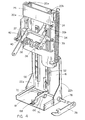
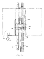
- the machine housing features of the present invention are best shown in Figures 3 - 6 and include a generally vertical slide track 16 which extends upwards and is connected to base 18. It is preferred that slide track 16 be formed of sheet metal and include a pair of vertical channels 20a and 20b, best shown in Figures 2 and 4 . To increase the connection strength between slide track 16 and base 18, a pair of reinforcement plates 22a and 22b, are preferably connected to slide track 16 and base 18 as shown in Figure 2 .
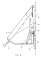
- a newspaper support trolley 24 which, in the preferred embodiment, includes a rear trolley section 26 and a front newspaper support plate 32 which extends forwards and downwards from the upper part of rear trolley section 26 as shown in Figures 4 and 6 .
- newspaper support plate 32 would be constructed of medium gauge sheet metal and would be inclined rearwardly at an angle between 30 degrees and 60 degrees although it is preferred that the actual angle of the newspaper support plate 32 be approximately 40 degrees.
- Mounted on the rear trolley section 26 adjacent to slide track 16 are a pair of track follower devices 30a and 30b which are preferably channel-engaging wheels designed to fit within and be in contact with the channels 20a and 20b on slide track 16. In this manner, newspaper support trolley 24 may travel in a generally vertical plane as directed by channels 20a and 20b and track follower devices 30a and 30b.
- a spring 34 is connected to an extension of rear plate 26 and extends upwards to connect to the slide track 16 at a point generally adjacent the top of slide track 16. The spring 34 assists the rack and gear mechanism which will be described in the following paragraph.
- first and second rack-engaging gear wheels 36 and 38 Mounted on the rear plate 26 of newspaper support trolley 24 are first and second rack-engaging gear wheels 36 and 38, each of which are rotatably mounted on a pivoting support mount 40, which is best shown in Figure 4 .
- the first gear wheel 36 is designed to engage a vertically mounted fixed toothed rack 50 which, in the preferred embodiment, is a toothed gear rack which extends approximately from the base of slide track 16 to top of side track 16 and is aligned colinearly with the direction of motion of the newspaper support trolley 24 up and down slide track 16.
- the fixed toothed rack 50 is preferably bolted to the slide track 16 at various points along the rack 50 to prevent movement of rack 50.
- the second gear wheel 38 is designed to engage a vertical moveable toothed rack 52, the vertically movable toothed rack 52 being free to move along a vertical line parallel with the line of movement of the newspaper support trolley 24 such that the second gear wheel 38 traveling on newspaper support trolley 24 engages toothed rack 52 at substantially all locations along toothed rack 52.
- first and second gear wheels 36 and 38 each include a respective clutch assembly 37 and 39 mounted within each of the first and second gear wheels 36 and 38, the clutch assemblies 37 and 39 operative to prevent rotation of the first and second gear wheels 36 and 38 in either direction, rather permitting rotation of the gear wheels 36 and 38 in a single direction only.
- clutch assembly 37 in gear wheel 36 permits the first gear wheel 36 to rotate in a clockwise direction, but prevents counter-clockwise rotation, as it is gear 36 which prevents newspaper support trolley 24 from moving downward when gear wheel 36 is engaged with tooth rack 50.
- the weight of the newspapers on the newspaper support trolley 24 would normally force the trolley to go downwards despite the biasing effect of biasing spring 34, but the presence of clutch 37 in gear wheel 36 prevents this rotation thus preventing downwards trolley movement when the gear wheel 36 is engaging rack 50.
- the reloading of newspapers would be performed by pivoting the gear wheels 36 and 38 away from racks 50 and 52 through outward movement of mount pivot bar 49 and then moving the newspaper support trolley 24 downwards along slide track 16.
- the papers are then placed on the newspaper support plate 32 and the pivoting support mount 40 is then rotated to reengage the gear wheels 36 and 38 with the toothed racks 50 and 52.
- the single vend newspaper machine 10 is then "primed" as will be described below.
- a forward bulkhead 54 which, in the preferred embodiment, would be a generally vertical sheet metal plate which includes rearwardly extending tabs to provide additional structural strength to the bulkhead 54.
- a newspaper thickness sensing bar 56 which is a generally flat steel bar including a generally horizontal foot section 58, two or more vertical connection slots 60a and 60b and an angled paper-engaging tab 62 which preferably extends generally parallel with the newspaper support plate 32 and extends over and above newspaper support plate 32 such that the top most paper on the stack of newspapers may be engaged by the underside of paper-engaging tab 62.
- Newspaper thickness sensing bar 56 is preferably biased upwards slightly by a spring (not shown) to at least partially offset the weight of newspaper thickness sensing bar 56 and to allow for easier vertical movement of the newspaper thickness sensing bar 56.
- vertically movable toothed rack 52 is connected to newspaper thickness sensing bar 56 by a strut 66 which is welded at one end thereof to vertically movable toothed rack 52 and includes at the opposite end thereof a generally horizontal foot 68 positioned such that foot 68 of diagonal strut 66 is seated on horizontal foot 58 of newspaper thickness sensing bar 56.
- a lift bar 72 and end-mounted roller 74 are fixedly mounted on a pivoting lift rod 76 which is rotatably mounted extending generally horizontally through base 18 to be attached to a lever arm 78 which extends perpendicular to lift rod 76 and forwards therefrom.
- lifting of lever 78 results in rotation of lift rod 76, which thus rotates lift bar 72 and causes roller 74 to contact the underside of strut 66.
- the roller 74 engaging strut 66 pushes diagonal strut upwards thus forcing vertical moveable toothed rack 52 upwards likewise.
- the newspaper support trolley 24 is moved upwards also, thus positioning the next paper in the rack for distribution.
- the extent to which roller 74 may raise strut 66 is limited by the length of lift bar 72 and, therefore, the length of lift bar 72 is critical to the invention as it is that length which determines the extent to which the vertically movable toothed rack 52 will be raised.
- the length of lift bar 72 would be such that the topmost paper on the stack would be moved to the proper dispensing position each and every time.
- An adjustment device such as a screw, inserted washers or the like may be included for fi ne adjustment of the position of the topmost newspaper the operation of which would be understood by those skilled in the art.
- a spring (not shown) preferably extends upwards from adjacent the base of vertically movable toothed rack 52 to a point above on slide track 16 as shown in Figure 3 to bias vertically movable toothed rack 52 upwards to at least partially offset the weight of vertically movable toothed rack 52 and strut 66.
- the door elements of the single vend newspaper vending machine 10 are best shown in Figures 2 , 3 and 7 -21 as including an operating handle 100 which is hinge mounted on the front of front door 14 as shown in Figures 1-3 .
- a standard coin intake mechanism 101 accepts the coins, ascertains that the correct coin amount has been inserted, and deposits them in a coin deposit box 84 shown best in Figure 2 .
- solenoid 103 fires which pivots bar 107 downwards as shown in Figures 11-13 .
- Bar 107 preferably includes a curved outer surface which allows the operating handle 100 to then be pulled forward by a person desiring the dispensing of a newspaper from the single vend newspaper vending machine 10, the operation of which will be described hereafter.
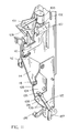
- the operating handle 100 is operatively connected to several different actuating mechanisms, but the main actuating mechanism is shown best in Figure 11 as including a generally upright plate 104 mounted on and extending downwards from the lower end of the operating handle 100, the plate including a semicircular cut 105 on the inner edge thereof, as shown in Figure 11 .
- the upwardly projecting leg of L-shaped arm 110 butts against bar box 102 when the handle 100 is pulled forward prior to the tripping of bar 107.
- stopping roller 116 prevents the handle from opening due to the roller 116 being seated in semicircular cut 105.
- solenoid 103 fires which pivots bar 107 downwards.
- L-shaped arm 110 is pivoted downwards and the pivot stop arm 114 which is pivotably connected to the frame adjacent arm 110 pivots slightly clockwise to disengage the stopping roller 116 mounted on stop arm 114 away from the semicircular cut 105 and permitting rotation of the handle 100.
- the stopping roller 116 rolls along the inner edge of the upright plate 104, and as the roller 116 does so, the L-shaped arm 110 is moved forwards towards the handle 100.
- the curved outer surface of bar 107 causes the L-shaped arm 110 to slide on the bar 107 until the rearward-pointing upper triangular section of the arm 110 is moved past the curved surface of the bar 107.
- the handle 100 After the handle 100 has been fully opened, as the handle 100 returns to its closed position, the rearward-pointing upper triangular section of the arm 110 moves back past the curved surface of the bar 107 and forcibly pivots the bar 107 upwards to return the bar 107 to its original position.
- the device thus resets until the proper coinage is input.
- the remaining features in Figures 11-13 are merely elements of a standard coin input device and are not elements of the present invention.
- metal actuating plate 208 connected to and extending from the lower end of the handle 100 is metal actuating plate 208, which in the preferred embodiment is adjacent operating handle 100 on the interior of the front door 14, the plate 208 connected to operating handle 100 such that rotation of operating handle 100 about its pivot point results in rotation of metal actuating plate 208 about pivot point 210.
- metal actuating plate 208 includes an arcuate slot 212 having left and right legs 214 and 216.
- a hydraulic cylinder 209 Connected to the top of metal actuating plate 208 is a hydraulic cylinder 209 which extends between metal actuating plate 208 and the interior of front door 14 as shown in Figure 4 , the hydraulic cylinder 209 biasing the handle 100 back to its rest position adjacent the door 14.
- a pusher mechanism actuation bar 120 is connected to plate 208 adjacent hydraulic cylinder 218, the actuation bar 120 extending upwards from metal actuating plate 208 to connect to the newspaper pusher mechanism 140, which will be described below.
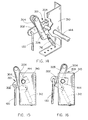
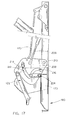
- a handle return prevention device 122 is mounted on the inner side of metal actuating plate 208, as shown in Figures 17 - 19, the handle return prevention device 122 operative to prevent operating handle 100 from returning to its rest position adjacent to coin intake mechanism 102 unless operating handle 100 has been pulled downwards the full extent permitted by the operating mechanism.
- Figures 11 and 17 -19 show the handle return prevention device 122, which includes a shift bar 135 pivotably connected to a ratchet bar 136 at one end thereof and including a transversely extended pin 134 which extends into slot 212.
- ratchet bar 136 Pivotably mounted on the opposite end of ratchet bar 136 is a ratchet 137 which ratchetly engages a ratchet plate 138 mounted on and extending inwards from door 14. If the handle 100 is not opened to its full extent and the operator attempts to return the handle 100 to its rest position, the ratchet 137 catches on ratchet plate 138 thus causing ratchet bar 136 to be retained in seat 139 in plate 208 until the operator finishes opening the handle 100 to its full extent. This will prevent operation of the newspaper vending machine 10 in an improper manner. Finally, mounted on paper release chute 170 is a gate mechanism 224 which prevents release of a paper to the paper release chute 170 until the operating handle 100 is pulled.
- Pusher mechanism actuation bar 120 is connected at the upper end thereof to an overcentering device 300 which includes a generally Y-shaped yoke 301 fixedly mounted via clamp and screw 308 on a pivot rod 144 which extends generally horizontally through left chute wall 126 and extends across the pusher mechanism 144 as shown in Figure 4 .
- the yoke 301 includes a generally horizontal arm 302 and a upwardly extending arm 304, actuation bar 120 connected to the outer end of arm 302 and arm 304 pivotably connected to L-shaped arm 306 as shown in Figure 14 .
- the lower end of L-shaped arm 306 is connected to bracket 310 via biasing spring 312 which operates to bias the lower end of L-shaped arm downwards.
- the overcentering device 300 is important to the present invention as it provides additional force for the removal of the paper-engaging needles of pusher mechanism 140 during the paper moving phase of the dispensing process, as will be described herein.
- the biasing force of spring 312 is added to the force of hydraulic or pneumatic cylinder 209 and additional retracting force is thus applied to the pusher mechanism 144 to enable retraction of the needles from even large papers.
- the additional force of biasing spring 312 is lessened and the handle 100 is returned to its original location by the operation of cylinder 209.
- the cylinder force also controls the operation of the paper gate as will be explained later in this disclosure, but it is important to note that the force applied to the gate is such that damage to the paper is avoided. Such judicious application of force would not be possible without the operation of the overcentering device as described above, and thus it is believed that the presently described overcentering device is an important feature of the present invention.
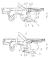
- Pusher mechanism 140 is preferably held within a generally U-shaped pusher mechanism housing 146 which houses a pair of pusher arms 148a and 148b which are operatively connected to pusher rod 144 such that rotation of pusher rod 144 results in extension of pusher arms 148a and 148b.
- Figures 7-10 disclose one variation of the operative connection between pusher rod 144 and pusher arms 148a and 148b, although it is to be understood that numerous modifications to the pusher mechanism 140 may be incorporated in the present invention so long as the basic functionality of the pusher mechanism 140 is not impaired.
- the engagement mechanism for pusher arms 148a and 148b includes elements on each side of the housing 146 and, therefore, the following description of the connection elements adjacent pusher arm 148a which operatively connect pusher arm 148a to pusher rod 144 should be understood to apply to the connection elements adjacent pusher arm 148b.
- Pusher arm 148a preferably includes an angle of approximately 45 degrees and is divided into a connection leg 150 and an engagement leg 152 which has at the end thereof a needle-equipped engagement wheel 160.
- the end of connection leg 150 is pivotably connected to a lower rod 153 which permits rotation of pusher arm 148a thereabout.
- a connection strut 154 extends from and is pivotably connected to lower rod 153 via short link 155, with the connection of connection strut 154 to connection leg 150 being a pivotable connection. Rotation of pusher rod 144 clockwise thus results in pusher arm 148a being pivoted away from the outer wall 132 of front door 14.
- a guide link 156 extends between a pivotable connection mounted on the housing 146 adjacent outer wall 132 of front door 14 and is rotatably connected to lower rod 153.
- Guide link 156 directs the movement of pusher arm 148a so that engagement leg 152 is moved forwards and downwards to engage the topmost paper 90 on the stack 92.
- Coiled springs 157a and 157b bias pusher arms 148a and 148b forwards and allow independent pivoting motion of the pusher arms 148a and 148b relative to one another to accommodate newspapers having odd-shaped inserts or the like.
- the pusher mechanism 140 thus operates in the following manner.
- overcentering device 300 is engaged as described above thus and pusher rod 144 is rotated in a clockwise manner.
- the rotation of pusher rod 144 moves connection strut 154 outward from outer wall 132 of front door 14 thus pivoting the pusher arms 148a and 148b from a rest position as shown in Figure 8 to an engagement position as shown in Figure 9 .
- connection strut 154 is further rotated and guide link 156 causes the engagement leg 152 and engagement wheel 160, and the needles thereon, to remain in contact with the topmost paper 90 thus forcing the topmost paper 90 rearward and upwards on the stack 92.
- the topmost paper 90 is thus removed from underneath the newspaper thickness sensing bar 56 and specifically the paper-engaging tab 62, allowing the newspaper thickness sensing bar 56 to fall downwards to contact the next highest paper 94 on stack 92.
- the overcentering device 300 is particularly necessary when thicker and heavier papers are being dispensed, as the needles on the engagement wheel 160 need to be securely pressed into the paper for proper dispensing.
- the additional force supplied by biasing spring 312 enables the proper operation of the invention in such situations.
- the pusher rod 144 When operating handle 100 is returned to its rest position, the pusher rod 144 is rotated counter-clockwise, thus reversing the motion of pusher arms 148a and 148b and allowing the topmost paper 90 to move downwards and forwards over the paper-engaging tab 62 of newspaper thickness sensing bar 56. As the pusher arms 148a and 148b return to their rest position, they disengage from the topmost paper 90 and gravity takes over as the topmost paper 90 slides forwards and downwards into the opening 172 of paper release chute 170. Because the elevator system has already moved the next highest paper 94 on the stack 92 to the position of the previous topmost paper 90, the entire process is ready to begin again.
- Gate mechanism 224 includes a gate bar 163 which is connected at one end to the gate 164 itself and at the other end to a pin 162 which extends transversely through right leg 116 of slot 112. Gate 164 is pivotably mounted adjacent chute 170 and closes off chute 170 when the handle 100 is in rest position. As the handle 100 is rotated, the pin 162 within slot 112 slides and causes rotation of the gate 164 to an open position, as shown in Figure 18 .
- the overcentering device 300 contributes to the operation of the present invention by providing additional force for the removal of the paper-engaging needles from the newspaper being dispensed without adding force to the closing of gate 164, which could result in paper damage and thus render the present invention unusable. It is important that the some type of newspaper pusher removal device that operates to increase the needle-removing force but which is isolated from the gate closing force, such as the above-described overcentering device 300, be provided, although it should be noted that numerous types of devices could be used which accomplish the same desired result.
- the lever-engaging bar 124 and roller 126 thereon engages the lever 78 during the performing of the above operations and during the rotation of handle 100.
- the lever-engaging bar 124 pushes the lever 78 upwards thus pivoting lift rod 76, lift bar 72 and roller 74, as shown best in Figures 2-4 .
- the above-described operations (the operation of the pusher mechanism and the opening of the gate) have occurred or are occurring. It is seen that the lift bar 72 is contacting the strut 66 in Figure 3 , and therefore has begun to move the rack 52 upwards along with the entire newspaper trolley 24.
- the distance "d" of the upwards shift of newspaper support trolley 24 is exactly equal to the thickness of the topmost newspaper 90 given by the distance fallen by the newspaper thickness sensing bar 56.
- the engagement of first gear wheel 36 with fixed toothed rack 50 keeps the newspaper support trolley 24 at the same height until the trolley is moved upwards as described above.
- a locking device 400 would be provided to secure the front door 14 of the invention in the closed position.
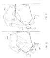
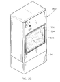
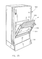
- Figures 22 and 23 disclose a second embodiment 500 of the present invention which in almost all respects internally operates exactly the same as the first embodiment herein.
- the second embodiment 500 is designed as a stand-alone unit having a pedestal 510 or the like and it is expected that if a dispensing chute such as that described in connection with the first embodiment were to be used, an individual would have to stoop to obtain a newspaper, which is undesirable. Therefore, the variation envisioned by the inventor is that as the topmost paper is removed from the stack of newspapers, it will fall into a display chute 502 which can be easily accessed by opening the front door 504 of the second embodiment 500, as shown in Figure 23 , and then reaching into the display chute 502 to remove the newspaper 506 on display therein.
- a metal plate would prevent access to the interior of the device when front door 504 is opened, as shown in Figure 23 .
- a gate (not shown) is opened to release the next newspaper on the stack into the display chute 502 and the process begins again. It is expected that the internal functional characteristics of this embodiment 500 will be substantially identical to those described in connection with the first embodiment.
Landscapes
- Physics & Mathematics (AREA)
- General Physics & Mathematics (AREA)
- Vending Machines For Individual Products (AREA)
- Control Of Vending Devices And Auxiliary Devices For Vending Devices (AREA)
- Basic Packing Technique (AREA)
Claims (8)
- Distributeur automatique de journaux pour vente à l'unité comprenant :un habillage de distributeur ayant des parois externes ;un système d'ascenseur à journaux monté dans ledit habillage de distributeur, ledit système d'ascenseur à journaux incluant :un moyen de glissière monté dans ledit habillage de distributeur ;une crémaillère fixe généralement verticale montée dans ledit habillage de distributeur ;une crémaillère verticale mobile verticalement montée de façon mobile dans ledit habillage de distributeur ;un chariot de support de journaux monté de façon mobile sur ledit moyen de glissière ;des première et seconde roues dentées équipées d'un embrayage, ladite première roue dentée équipée d'un embrayage étant opérationnelle pour s'engager avec ladite crémaillère fixe, ladite seconde roue dentée équipée d'un embrayage étant opérationnelle pour s'engager avec ladite crémaillère mobile verticalement ;ledit moyen de glissière, ladite crémaillère fixe, ladite crémaillère mobile verticalement et ledit chariot de support de journaux étant montés dans ledit habillage de distributeur de telle sorte que lorsque ledit chariot de support de journaux est monté de façon mobile sur ledit moyen de glissière, ladite première roue dentée équipée d'un embrayage s'engage avec ladite crémaillère fixe et ladite seconde roue dentée équipée d'un embrayage s'engage avec ladite crémaillère mobile verticalement ;ladite première roue dentée équipée d'un embrayage étant opérationnelle pour restreindre un mouvement vers le bas dudit chariot de support de journaux lorsqu'elle s'engage avec ladite crémaillère fixe, ladite seconde roue dentée équipée d'un embrayage étant opérationnelle pour permettre un mouvement vers le bas de ladite crémaillère mobile verticalement, un mouvement vers le haut de ladite crémaillère mobile verticalement amenant ledit chariot de support de journaux à se déplacer vers le haut avec celle-ci ;un moyen de détection d'épaisseur de journal monté de façon mobile dans ledit habillage de distributeur et opérationnel pour déterminer l'épaisseur du journal le plus haut ;un moyen de poussée de journal monté dans ledit habillage de distributeur opérationnel pour s'engager avec un journal le plus haut sur une pile de journaux supportée sur ledit chariot de support de journaux et extraire le journal le plus haut hors de la pile de journaux par glissement ;une ouverture d'accès s'étendant à travers ledit habillage de distributeur, ladite ouverture d'accès étant opérationnelle pour permettre l'accès au journal le plus haut après que le journal le plus haut a été extrait de la pile de journaux par glissement ;un moyen de commande de l'ouverture d'accès monté adjacent à ladite ouverture d'accès, ledit moyen de commande de l'ouverture d'accès incluant une porte opérationnelle pour couvrir ladite ouverture d'accès et un moyen de commande de l'ouverture de porte pour verrouiller de façon libérable ladite porte dans une position fermée de couverture de l'ouverture d'accès ; etun moyen d'actionnement du moyen de poussée de journal et de la crémaillère mobile raccordé de façon opérationnelle audit moyen de poussée de journal et à ladite crémaillère mobile de telle sorte qu'un engagement dudit moyen d'actionnement premièrement actionne le moyen de poussée de journal pour enlever le journal le plus haut de la pile de journaux, ledit moyen d'actionnement étant opérationnel pour deuxièmement élever ladite crémaillère mobile d'une distance déterminée par l'épaisseur du journal le plus haut telle que déterminée par le moyen de détection d'épaisseur de journal, élevant ainsi ledit chariot de support de journaux de telle sorte que le pénultième journal remplace le journal le plus haut distribué dans sensiblement la même position que celle du journal le plus haut avant sa distribution.
- Distributeur automatique de journaux pour vente à l'unité selon la revendication 1, dans lequel ledit chariot de support de journaux comprend en outre une plaque de support de journaux inclinée pour supporter une pile de journaux.
- Distributeur automatique de journaux pour vente à l'unité selon la revendication 2, dans lequel ledit moyen de détection d'épaisseur de journal comprend une barre en acier généralement plate incluant une languette inclinée d'engagement de journal qui s'étend de préférence généralement parallèlement à ladite plaque de support de journaux et s'étend sur et au-dessus de ladite plaque de support de journaux de telle sorte que le journal le plus haut sur la pile de journaux peut s'engager avec la face inférieure de ladite languette d'engagement de journal, ledit moyen de détection d'épaisseur de journal étant opérationnel pour déterminer l'épaisseur du journal le plus haut par déplacement vers le bas pour venir en contact avec le pénultième journal sur la pile lorsque le journal le plus haut est déplacé depuis au-dessous de ladite languette d'engagement de journal par ledit moyen de poussée de journal, l'épaisseur du journal le plus haut étant égale à la distance déplacée vers le bas par ledit moyen de détection d'épaisseur de journal.
- Distributeur automatique de journaux pour vente à l'unité selon la revendication 1, dans lequel ledit moyen de poussée de journal comprend au moins un bras pousseur monté de façon mobile au-dessus de et adjacent à la position du journal le plus haut, ledit bras pousseur ayant un moyen d'engagement à aiguille pour percer légèrement la surface supérieure du journal le plus haut, ledit bras étant opérationnel pour déplacer le journal le plus haut vers une position de distribution.
- Distributeur automatique de journaux pour vente à l'unité selon la revendication 1, dans lequel ledit moyen d'actionnement du moyen de poussée de journal et de l'organe mobile de commande de hauteur comprend une poignée d'opération montée de façon pivotante montée sur l'extérieur dudit habillage de distributeur, ladite poignée d'opération étant raccordée de façon opérationnelle audit moyen de poussée de journal et audit organe mobile de commande de hauteur de telle sorte qu'une rotation de ladite poignée premièrement amène ledit moyen de poussée de journal à déloger le journal le plus haut pour qu'il soit distribué et deuxièmement élève ledit organe de commande de hauteur d'une distance déterminée par l'épaisseur du journal le plus haut telle que déterminée par le moyen de détection d'épaisseur de journal, élevant ainsi ledit chariot de support de journaux de telle sorte que le pénultième journal remplace le journal le plus haut distribué dans sensiblement la même position que le journal le plus haut était avant sa distribution.
- Distributeur automatique de journaux pour vente à l'unité selon la revendication 1, comprenant en outre un dispositif de surcentrage interposé de façon opérationnelle entre ledit moyen d'actionnement du moyen de poussée de journal et de l'organe de commande de hauteur mobile et ledit moyen de poussée de journal, ledit dispositif de surcentrage étant opérationnel pour traduire l'actionnement dudit moyen d'actionnement en une force additionnelle pour retirer ledit moyen de poussée de journal d'un journal qui est distribué pendant la phase de déplacement de journal du processus de distribution, moyennant quoi des journaux plus grands et plus épais sont correctement distribués.
- Distributeur automatique de journaux pour vente à l'unité selon la revendication 1, comprenant en outre un dispositif d'introduction de pièces de monnaie opérationnel pour accepter des pièces de monnaie et restreindre le fonctionnement dudit moyen d'actionnement du moyen de poussée de journal et de l'organe mobile de commande de hauteur à moins que la quantité correcte de pièces est déposée dans ledit dispositif d'introduction de pièces de monnaie.
- Distributeur automatique de journaux pour vente à l'unité selon la revendication 5, dans lequel ladite poignée d'opération montée de façon pivotante montée sur l'extérieur dudit habillage de distributeur est dépourvue de mécanisme de verrouillage monté de façon externe, moyennant quoi une mise hors service intentionnelle du fonctionnement dudit distributeur de journaux pour vente à l'unité en forçant le mécanisme de verrouillage est généralement empêchée.
Applications Claiming Priority (3)
| Application Number | Priority Date | Filing Date | Title |
|---|---|---|---|
| US13940099P | 1999-06-16 | 1999-06-16 | |
| US139400P | 1999-06-16 | ||
| PCT/US2000/016484 WO2000076892A1 (fr) | 1999-06-16 | 2000-06-14 | Distributeur automatique de journaux pour vente a l'unite |
Publications (3)
| Publication Number | Publication Date |
|---|---|
| EP1230138A1 EP1230138A1 (fr) | 2002-08-14 |
| EP1230138A4 EP1230138A4 (fr) | 2004-03-31 |
| EP1230138B1 true EP1230138B1 (fr) | 2010-07-21 |
Family
ID=22486455
Family Applications (1)
| Application Number | Title | Priority Date | Filing Date |
|---|---|---|---|
| EP00944686A Expired - Lifetime EP1230138B1 (fr) | 1999-06-16 | 2000-06-14 | Distributeur automatique de journaux pour vente a l'unite |
Country Status (6)
| Country | Link |
|---|---|
| US (1) | US6439425B1 (fr) |
| EP (1) | EP1230138B1 (fr) |
| AT (1) | ATE475160T1 (fr) |
| AU (1) | AU5874700A (fr) |
| DE (1) | DE60044721D1 (fr) |
| WO (1) | WO2000076892A1 (fr) |
Families Citing this family (25)
| Publication number | Priority date | Publication date | Assignee | Title |
|---|---|---|---|---|
| US6622889B2 (en) * | 2002-01-15 | 2003-09-23 | Randall L. Dunn | Secure vending machine |
| US20040050855A1 (en) * | 2002-09-17 | 2004-03-18 | Gordon Jurgenson | Vending machine |
| US7077288B2 (en) | 2003-06-06 | 2006-07-18 | Mcmillen Russell G | Newspaper vending machine |
| US7204360B2 (en) * | 2003-10-28 | 2007-04-17 | Stu Rasmussen | Coin or token actuated multiple choice selector |
| US7234610B2 (en) * | 2005-02-10 | 2007-06-26 | Northern Products Development Group Llc | Automatic napkin dispenser |
| US8074987B2 (en) | 2005-02-10 | 2011-12-13 | Bally Gaming, Inc. | Systems and methods for processing playing cards collected from a gaming table |
| US8342533B2 (en) | 2005-09-12 | 2013-01-01 | Bally Gaming, Inc. | Systems, methods and articles to facilitate playing card games with multi-compartment playing card receivers |
| US8342932B2 (en) | 2005-09-12 | 2013-01-01 | Bally Gaming, Inc. | Systems, methods and articles to facilitate playing card games with intermediary playing card receiver |
| US8550464B2 (en) | 2005-09-12 | 2013-10-08 | Bally Gaming, Inc. | Systems, methods and articles to facilitate playing card games with selectable odds |
| DE202005016442U1 (de) * | 2005-10-20 | 2006-01-19 | Wall Aktiengesellschaft | Vertriebsbehälter für Printmedien, insbesondere Zeitungen |
| US20070138743A1 (en) * | 2005-12-19 | 2007-06-21 | Bally Gaming Inc. | Card shoe with force resist mechanism |
| US20070216092A1 (en) * | 2006-03-15 | 2007-09-20 | Bally Gaming, Inc. | Card shoe for holding playing cards |
| RU2316053C1 (ru) * | 2006-05-02 | 2008-01-27 | Закрытое акционерное общество "Автоматпроизводство" | Торговый автомат |
| US8038153B2 (en) | 2006-05-23 | 2011-10-18 | Bally Gaming, Inc. | Systems, methods and articles to facilitate playing card games |
| US8100753B2 (en) * | 2006-05-23 | 2012-01-24 | Bally Gaming, Inc. | Systems, methods and articles to facilitate playing card games with selectable odds |
| US8052519B2 (en) | 2006-06-08 | 2011-11-08 | Bally Gaming, Inc. | Systems, methods and articles to facilitate lockout of selectable odds/advantage in playing card games |
| US8998692B2 (en) | 2006-06-21 | 2015-04-07 | Bally Gaming, Inc. | Systems, methods and articles to facilitate delivery of sets or packets of playing cards |
| US8070574B2 (en) | 2007-06-06 | 2011-12-06 | Shuffle Master, Inc. | Apparatus, system, method, and computer-readable medium for casino card handling with multiple hand recall feature |
| US9101820B2 (en) | 2006-11-09 | 2015-08-11 | Bally Gaming, Inc. | System, method and apparatus to produce decks for and operate games played with playing cards |
| AT505480B1 (de) * | 2007-06-18 | 2009-05-15 | Farbdruck Gmbh | Vorrichtung zur vereinzelten ausgabe von druckereierzeugnissen |
| ITMO20070281A1 (it) * | 2007-09-13 | 2009-03-14 | Cefriel Societa Consortile A R | Sistema di distribuzione di pubblicazioni a stampa |
| US9640014B2 (en) | 2011-01-04 | 2017-05-02 | Fawn Engineering Corporation | Vending machine with elevator delivery of vended product to customer access |
| RU2556381C2 (ru) * | 2013-03-05 | 2015-07-10 | Андрей Михайлович Шелепов | Торговый автомат |
| US9870671B1 (en) | 2014-04-07 | 2018-01-16 | Fawn Engineering Corporation | Mechanical lift for delivery bins in vending machines |
| CN110148258B (zh) * | 2019-06-25 | 2024-01-30 | 河南通达多媒体制作有限公司 | 一种自动售报装置 |
Family Cites Families (17)
| Publication number | Priority date | Publication date | Assignee | Title |
|---|---|---|---|---|
| US3747733A (en) * | 1970-01-19 | 1973-07-24 | K Knickerbocker | Newspaper dispensing machine with means to compensate for decreasing supply |
| US3709405A (en) * | 1970-10-29 | 1973-01-09 | C Harris | Vending machine for periodicals having arcuate path ejection |
| US4319695A (en) * | 1977-12-27 | 1982-03-16 | Dutro Lyle V | Vendor for flat articles |
| US4174047A (en) * | 1978-03-06 | 1979-11-13 | 3-in-1, Inc. | Vending machine for newspapers and the like |
| US4299335A (en) * | 1979-03-28 | 1981-11-10 | Hickey-Mitchell Company | Newspaper vendor |
| US4312461A (en) * | 1980-06-25 | 1982-01-26 | Godley Sr Fred O | Newspaper vending machine |
| US4413749A (en) * | 1981-06-05 | 1983-11-08 | Single Vend, Inc. | Newspaper dispensing apparatus and method |
| US4428503A (en) * | 1981-12-07 | 1984-01-31 | Denmar Engineering & Control Systems, Inc. | Vending machine for insuring the dispensing of newspapers and the like one at a time |
| US4569461A (en) * | 1982-07-30 | 1986-02-11 | Berkley-Small, Inc. | Single copy newspaper dispensing machine |
| US4496074A (en) * | 1982-08-12 | 1985-01-29 | Mfg. Design, Inc. | Newspaper vending machine |
| US4583658A (en) * | 1983-10-24 | 1986-04-22 | Benjamin Israel | Single newspaper vending machine |
| US4566608A (en) * | 1984-05-24 | 1986-01-28 | Draper Technologies, Inc. | System for converting stack access newspaper vending machines and the like to apparatus for dispensing products one at a time |
| US4707038A (en) * | 1986-01-08 | 1987-11-17 | Voegeli Ronald C | Display rack |
| US4865178A (en) * | 1987-06-18 | 1989-09-12 | Lew Enterprises, Inc. | Single copy vending machine for newspapers and the like |
| NO167194C (no) * | 1989-01-20 | 1991-10-16 | Media Craft As | Innretning for fraskillelse av et antall blader e.l. fra en stabel av blader e.l. |
| DE29605773U1 (de) * | 1996-03-28 | 1996-08-01 | Wenner, Hans, 69126 Heidelberg | Vorrichtung zur Ausgabe von Druckerzeugnissen, insbesondere Zeitungen und Zeitschriften |
| US6003725A (en) * | 1997-03-28 | 1999-12-21 | Blankenau; Edmund H. | Single vend newspaper vending machine |
-
2000
- 2000-06-14 EP EP00944686A patent/EP1230138B1/fr not_active Expired - Lifetime
- 2000-06-14 DE DE60044721T patent/DE60044721D1/de not_active Expired - Lifetime
- 2000-06-14 US US09/594,548 patent/US6439425B1/en not_active Expired - Fee Related
- 2000-06-14 AU AU58747/00A patent/AU5874700A/en not_active Abandoned
- 2000-06-14 AT AT00944686T patent/ATE475160T1/de not_active IP Right Cessation
- 2000-06-14 WO PCT/US2000/016484 patent/WO2000076892A1/fr not_active Ceased
Also Published As
| Publication number | Publication date |
|---|---|
| WO2000076892A1 (fr) | 2000-12-21 |
| ATE475160T1 (de) | 2010-08-15 |
| AU5874700A (en) | 2001-01-02 |
| DE60044721D1 (de) | 2010-09-02 |
| EP1230138A1 (fr) | 2002-08-14 |
| EP1230138A4 (fr) | 2004-03-31 |
| US6439425B1 (en) | 2002-08-27 |
Similar Documents
| Publication | Publication Date | Title |
|---|---|---|
| US6439425B1 (en) | Single vend newspaper vending machine | |
| EP0958558B1 (fr) | Distributeur automatique de journaux et periodiques | |
| US3180518A (en) | Mechanical vendor for articles | |
| GB2386116A (en) | Product dispenser | |
| US6003725A (en) | Single vend newspaper vending machine | |
| US4251009A (en) | Security door assembly for an automatic document dispensing device | |
| US4312461A (en) | Newspaper vending machine | |
| US4700869A (en) | Single item vending machine | |
| US4174047A (en) | Vending machine for newspapers and the like | |
| US4331261A (en) | Retrofit single-newspaper security dispenser | |
| US4718532A (en) | Coin operated vending machines for newspapers or the like | |
| US4258861A (en) | Single-paper vending apparatus | |
| US4566608A (en) | System for converting stack access newspaper vending machines and the like to apparatus for dispensing products one at a time | |
| US5531355A (en) | Single vend machine | |
| US4140242A (en) | Newspaper and periodical single-copy vending machine | |
| CA1228057A (fr) | Distributeur automatique d'articles places a l'horizontale, tels des journaux | |
| JPH0117197B2 (fr) | ||
| US4530444A (en) | Separation device for single copy newspaper vendor | |
| US7770753B2 (en) | Single vend newspaper vending machine | |
| US7819282B2 (en) | Newspaper vending machine | |
| US5143251A (en) | Single vend device for a newspaper vending machine | |
| US4981236A (en) | Anti-theft device for use in a coin-operated dispensing machine for newspapers and the like | |
| US5431300A (en) | Single vend device for a newspaper vending machine | |
| US6279719B1 (en) | Vending machine for dispensing single copies of periodicals and newspapers | |
| US6112941A (en) | Single vend newspaper vending machine |
Legal Events
| Date | Code | Title | Description |
|---|---|---|---|
| PUAI | Public reference made under article 153(3) epc to a published international application that has entered the european phase |
Free format text: ORIGINAL CODE: 0009012 |
|
| 17P | Request for examination filed |
Effective date: 20011219 |
|
| AK | Designated contracting states |
Kind code of ref document: A1 Designated state(s): AT BE CH CY DE DK ES FI FR GB GR IE IT LI LU MC NL PT SE |
|
| AX | Request for extension of the european patent |
Free format text: AL;LT;LV;MK;RO;SI |
|
| A4 | Supplementary search report drawn up and despatched |
Effective date: 20040216 |
|
| RIC1 | Information provided on ipc code assigned before grant |
Ipc: 7G 07F 11/04 B Ipc: 7G 07F 11/14 A Ipc: 7B 65H 3/22 B |
|
| 17Q | First examination report despatched |
Effective date: 20040521 |
|
| GRAP | Despatch of communication of intention to grant a patent |
Free format text: ORIGINAL CODE: EPIDOSNIGR1 |
|
| GRAS | Grant fee paid |
Free format text: ORIGINAL CODE: EPIDOSNIGR3 |
|
| GRAA | (expected) grant |
Free format text: ORIGINAL CODE: 0009210 |
|
| AK | Designated contracting states |
Kind code of ref document: B1 Designated state(s): AT BE CH CY DE DK ES FI FR GB GR IE IT LI LU MC NL PT SE |
|
| REG | Reference to a national code |
Ref country code: GB Ref legal event code: FG4D |
|
| REG | Reference to a national code |
Ref country code: CH Ref legal event code: EP |
|
| REG | Reference to a national code |
Ref country code: IE Ref legal event code: FG4D |
|
| REG | Reference to a national code |
Ref country code: NL Ref legal event code: T3 |
|
| REF | Corresponds to: |
Ref document number: 60044721 Country of ref document: DE Date of ref document: 20100902 Kind code of ref document: P |
|
| PG25 | Lapsed in a contracting state [announced via postgrant information from national office to epo] |
Ref country code: FI Free format text: LAPSE BECAUSE OF FAILURE TO SUBMIT A TRANSLATION OF THE DESCRIPTION OR TO PAY THE FEE WITHIN THE PRESCRIBED TIME-LIMIT Effective date: 20100721 Ref country code: AT Free format text: LAPSE BECAUSE OF FAILURE TO SUBMIT A TRANSLATION OF THE DESCRIPTION OR TO PAY THE FEE WITHIN THE PRESCRIBED TIME-LIMIT Effective date: 20100721 |
|
| PG25 | Lapsed in a contracting state [announced via postgrant information from national office to epo] |
Ref country code: PT Free format text: LAPSE BECAUSE OF FAILURE TO SUBMIT A TRANSLATION OF THE DESCRIPTION OR TO PAY THE FEE WITHIN THE PRESCRIBED TIME-LIMIT Effective date: 20101122 Ref country code: CY Free format text: LAPSE BECAUSE OF FAILURE TO SUBMIT A TRANSLATION OF THE DESCRIPTION OR TO PAY THE FEE WITHIN THE PRESCRIBED TIME-LIMIT Effective date: 20100721 |
|
| PG25 | Lapsed in a contracting state [announced via postgrant information from national office to epo] |
Ref country code: SE Free format text: LAPSE BECAUSE OF FAILURE TO SUBMIT A TRANSLATION OF THE DESCRIPTION OR TO PAY THE FEE WITHIN THE PRESCRIBED TIME-LIMIT Effective date: 20100721 Ref country code: BE Free format text: LAPSE BECAUSE OF FAILURE TO SUBMIT A TRANSLATION OF THE DESCRIPTION OR TO PAY THE FEE WITHIN THE PRESCRIBED TIME-LIMIT Effective date: 20100721 Ref country code: GR Free format text: LAPSE BECAUSE OF FAILURE TO SUBMIT A TRANSLATION OF THE DESCRIPTION OR TO PAY THE FEE WITHIN THE PRESCRIBED TIME-LIMIT Effective date: 20101022 |
|
| PG25 | Lapsed in a contracting state [announced via postgrant information from national office to epo] |
Ref country code: DK Free format text: LAPSE BECAUSE OF FAILURE TO SUBMIT A TRANSLATION OF THE DESCRIPTION OR TO PAY THE FEE WITHIN THE PRESCRIBED TIME-LIMIT Effective date: 20100721 |
|
| PLBE | No opposition filed within time limit |
Free format text: ORIGINAL CODE: 0009261 |
|
| STAA | Information on the status of an ep patent application or granted ep patent |
Free format text: STATUS: NO OPPOSITION FILED WITHIN TIME LIMIT |
|
| PG25 | Lapsed in a contracting state [announced via postgrant information from national office to epo] |
Ref country code: IT Free format text: LAPSE BECAUSE OF FAILURE TO SUBMIT A TRANSLATION OF THE DESCRIPTION OR TO PAY THE FEE WITHIN THE PRESCRIBED TIME-LIMIT Effective date: 20100721 |
|
| 26N | No opposition filed |
Effective date: 20110426 |
|
| PG25 | Lapsed in a contracting state [announced via postgrant information from national office to epo] |
Ref country code: ES Free format text: LAPSE BECAUSE OF FAILURE TO SUBMIT A TRANSLATION OF THE DESCRIPTION OR TO PAY THE FEE WITHIN THE PRESCRIBED TIME-LIMIT Effective date: 20101101 |
|
| REG | Reference to a national code |
Ref country code: DE Ref legal event code: R097 Ref document number: 60044721 Country of ref document: DE Effective date: 20110426 |
|
| REG | Reference to a national code |
Ref country code: NL Ref legal event code: V1 Effective date: 20120101 |
|
| REG | Reference to a national code |
Ref country code: CH Ref legal event code: PL |
|
| GBPC | Gb: european patent ceased through non-payment of renewal fee |
Effective date: 20110614 |
|
| REG | Reference to a national code |
Ref country code: FR Ref legal event code: ST Effective date: 20120229 |
|
| REG | Reference to a national code |
Ref country code: IE Ref legal event code: MM4A |
|
| REG | Reference to a national code |
Ref country code: DE Ref legal event code: R119 Ref document number: 60044721 Country of ref document: DE Effective date: 20120103 |
|
| PG25 | Lapsed in a contracting state [announced via postgrant information from national office to epo] |
Ref country code: DE Free format text: LAPSE BECAUSE OF NON-PAYMENT OF DUE FEES Effective date: 20120103 Ref country code: IE Free format text: LAPSE BECAUSE OF NON-PAYMENT OF DUE FEES Effective date: 20110614 Ref country code: FR Free format text: LAPSE BECAUSE OF NON-PAYMENT OF DUE FEES Effective date: 20110630 Ref country code: LI Free format text: LAPSE BECAUSE OF NON-PAYMENT OF DUE FEES Effective date: 20110630 Ref country code: CH Free format text: LAPSE BECAUSE OF NON-PAYMENT OF DUE FEES Effective date: 20110630 |
|
| PG25 | Lapsed in a contracting state [announced via postgrant information from national office to epo] |
Ref country code: NL Free format text: LAPSE BECAUSE OF NON-PAYMENT OF DUE FEES Effective date: 20120101 |
|
| PG25 | Lapsed in a contracting state [announced via postgrant information from national office to epo] |
Ref country code: GB Free format text: LAPSE BECAUSE OF NON-PAYMENT OF DUE FEES Effective date: 20110614 |
|
| PG25 | Lapsed in a contracting state [announced via postgrant information from national office to epo] |
Ref country code: MC Free format text: LAPSE BECAUSE OF NON-PAYMENT OF DUE FEES Effective date: 20110630 |
|
| PG25 | Lapsed in a contracting state [announced via postgrant information from national office to epo] |
Ref country code: LU Free format text: LAPSE BECAUSE OF NON-PAYMENT OF DUE FEES Effective date: 20110614 |