EP1230872A1 - Colonne de levage de préférence pour mobilier tel que tables et lits - Google Patents
Colonne de levage de préférence pour mobilier tel que tables et lits Download PDFInfo
- Publication number
- EP1230872A1 EP1230872A1 EP02075543A EP02075543A EP1230872A1 EP 1230872 A1 EP1230872 A1 EP 1230872A1 EP 02075543 A EP02075543 A EP 02075543A EP 02075543 A EP02075543 A EP 02075543A EP 1230872 A1 EP1230872 A1 EP 1230872A1
- Authority
- EP
- European Patent Office
- Prior art keywords
- spindle
- lifting column
- column according
- motor
- column
- Prior art date
- Legal status (The legal status is an assumption and is not a legal conclusion. Google has not performed a legal analysis and makes no representation as to the accuracy of the status listed.)
- Granted
Links
- 230000005540 biological transmission Effects 0.000 claims abstract description 13
- 238000006073 displacement reaction Methods 0.000 claims abstract description 3
- XAGFODPZIPBFFR-UHFFFAOYSA-N aluminium Chemical compound [Al] XAGFODPZIPBFFR-UHFFFAOYSA-N 0.000 claims 1
- 229910052782 aluminium Inorganic materials 0.000 claims 1
- 239000004411 aluminium Substances 0.000 claims 1
- 230000002441 reversible effect Effects 0.000 claims 1
- 230000002349 favourable effect Effects 0.000 abstract 1
- 229920003023 plastic Polymers 0.000 description 3
- 239000004033 plastic Substances 0.000 description 3
- XEEYBQQBJWHFJM-UHFFFAOYSA-N Iron Chemical compound [Fe] XEEYBQQBJWHFJM-UHFFFAOYSA-N 0.000 description 2
- 230000000694 effects Effects 0.000 description 2
- 230000002411 adverse Effects 0.000 description 1
- 238000010586 diagram Methods 0.000 description 1
- 229910052742 iron Inorganic materials 0.000 description 1
Images

Classifications
-
- A—HUMAN NECESSITIES
- A47—FURNITURE; DOMESTIC ARTICLES OR APPLIANCES; COFFEE MILLS; SPICE MILLS; SUCTION CLEANERS IN GENERAL
- A47C—CHAIRS; SOFAS; BEDS
- A47C19/00—Bedsteads
- A47C19/04—Extensible bedsteads, e.g. with adjustment of length, width, height
- A47C19/045—Extensible bedsteads, e.g. with adjustment of length, width, height with entire frame height or inclination adjustments
-
- A—HUMAN NECESSITIES
- A47—FURNITURE; DOMESTIC ARTICLES OR APPLIANCES; COFFEE MILLS; SPICE MILLS; SUCTION CLEANERS IN GENERAL
- A47B—TABLES; DESKS; OFFICE FURNITURE; CABINETS; DRAWERS; GENERAL DETAILS OF FURNITURE
- A47B9/00—Tables with tops of variable height
- A47B9/04—Tables with tops of variable height with vertical spindle
-
- A—HUMAN NECESSITIES
- A47—FURNITURE; DOMESTIC ARTICLES OR APPLIANCES; COFFEE MILLS; SPICE MILLS; SUCTION CLEANERS IN GENERAL
- A47B—TABLES; DESKS; OFFICE FURNITURE; CABINETS; DRAWERS; GENERAL DETAILS OF FURNITURE
- A47B9/00—Tables with tops of variable height
- A47B9/20—Telescopic guides
-
- A—HUMAN NECESSITIES
- A47—FURNITURE; DOMESTIC ARTICLES OR APPLIANCES; COFFEE MILLS; SPICE MILLS; SUCTION CLEANERS IN GENERAL
- A47B—TABLES; DESKS; OFFICE FURNITURE; CABINETS; DRAWERS; GENERAL DETAILS OF FURNITURE
- A47B2200/00—General construction of tables or desks
- A47B2200/0035—Tables or desks with features relating to adjustability or folding
- A47B2200/005—Leg adjustment
- A47B2200/0056—Leg adjustment with a motor, e.g. an electric motor
- A47B2200/0059—Leg adjustment with a motor, e.g. an electric motor in telescoping table legs
Definitions
- the present invention relates to a lifting column of the type stated in the introductory portion of claim 1.
- lifting columns for height-adjustable tables are chosen as a basis.
- the columns consist of two or three mutually telescopically slidable tubular profile members.
- An electrically driven linear actuator, concealed within the column, is typically used as a drive unit.
- the actuators are of the type which is based on a spindle driven by an electric motor.
- a tubular drive rod is connected with a spindle nut, and rotation of the spindle causes the drive rod to be extended or retracted depending on the direction of rotation of the spindle.
- the stroke of the actuator is directly related to its mounting dimensions, which involves a conflict between the mounting dimensions of the column and the desired minimum and maximum height of the column. In reality, the achievable maximum and minimum height is a compromise where each millimetre in mounting dimensions and stroke counts.
- the internal position of the actuator has a further adverse influence on the minimum/maximum height ratio.
- control box containing a low volt power supply (DC 24V/48V) based on a transformer and a control device.
- the wiring is rather comprehensive, as the control box is wired to the mains and is connected to the actuator as well as a control panel.
- the control box is placed below the tabletop, and therefore it is necessary to take measures against electrical and magnetic impacts from there in order to avoid impacts on equipment positioned on the tabletop.
- the control box is placed loosely on the floor, which is obviously not satisfactory.
- the object of the invention is to improve the ratio of mounting dimension to stroke of the column as well as its stability.
- a column according to the invention which is characterized in that the spindle is secured at the end of one member, that the spindle nut is connected with the adjacent end of the other member, and that the spindle nut may be caused to rotate by the motor via a transmission to bring about telescopic displacement of the members.
- the electrical equipment may be arranged in the member with the motor.
- the column may thus be finish-mounted at the factory, and moreover it has advantages in terms of electrical and magnetic shielding to place power supply and control enclosed in a metallic tube.
- the motor is arranged with the motor shaft in parallel with the spindle, which allows a column of slim cross-section.
- the motor is arranged with the motor shaft perpendicular to the spindle. This gives a lower mounting height, but it requires a larger cross-section of the column in the longitudinal extent of the motor.
- the embodiment makes it directly possible to use a worm drive in the transmission. This is reliable and gives a good gearing down of the motor speed, just as it involves a low level of noise.
- the spindle is secured at the end of the outer member, while the motor and the transmission as well as the spindle nut are arranged in the movable member.
- the outer member may be arranged at the bottom, i.e. stationary, while the inner member may move out and in.
- the inner member may be arranged at the bottom, i.e. stationary, while the outer member moves up and down this.
- the column comprises three members, and the motor and the transmission are secured at the end of the inner member. Seated here is also the spindle nut which cooperates with a hollow spindle that extends through the intermediate member and is secured at the opposite end thereof. A spindle is secured at the remote end of the outer member, and this spindle is seated in the hollow spindle and cooperates with a spindle nut.
- the spindle nut may be formed with a gear wheel, expediently having an internal toothing.
- Nut and gear wheel may be moulded of plastics as an integral unit.
- the spindle nut is coupled to the side of a separate gear wheel.
- the end face of the nut may e.g. be formed with pins that extend into holes in the side of the gear wheel, or vice versa.
- the engagement faces may also be provided with carrier teeth.
- the gear wheel may also have a cylindrical portion in which the nut is seated completely or partly and is coupled by means of a splined connection.
- the spindle nut or another cylindrical element in the transmission is provided with a helical spring, whose one end is fixed in the structure, and whose turns extend such that the spring exerts a braking force when the column is retracted. It is hereby possible to impart a self-blocking capability to the column or to increase its self-blocking capability when it is lowered.
- the braking effect of the spring is determined empirically on the basis of the given purpose.
- the power supply and/or the control electronics may be arranged inside the column.
- it is arranged in the member with the motor.
- the transformer may be arranged deep inside the member, it is possible to use a simple form of transformer, since it is well shielded, because the top of the column will typically be covered by an iron plate which is used as a mounting bracket for the column.
- a ring core transformer this may be arranged such that the spindle may pass through its inner opening.
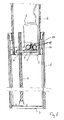
- the column comprises an outer tube 1 and an inner tube 2 telescopically mounted in the outer tube.
- the outer tube has an end bottom 3 to which a spindle 4 is secured with its end.
- At the adjacent end of the inner tube there is an end bottom 5 that forms the chassis for an electric motor 6, a transmission 7 and a spindle nut 8.
- the spindle nut is provided with an external toothing which is in engagement with a gear wheel 9 in the transmission.
- a toothing 10 is provided on the side of the gear wheel, said toothing engaging two diametrically positioned gear wheels 11. Further, a worm wheel is provided in extension of these two gear wheels, said worm wheel being engaged with a worm 12 from the motor 6.
- the spindle nut 8 When the motor is started in one direction of rotation, the spindle nut 8 will rotate in one direction and move up the spindle 4 and thereby push the inner tube 2 out. When the direction of rotation of the motor is reversed, the spindle nut 8 will rotate in the other direction and will then move down the spindle 4, thereby retracting the inner tube 2. As will appear, the lifting height of the column may substantially be maximized to the length of the outer tube 1. Then, the size of the overlap may be chosen freely, depending on the desired stability of the column.
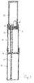
- Fig. 2 of the drawing shows an embodiment in which the spindle nut 8 is coupled to the side of a gear wheel 13 in that the nut 8 has a protruding portion 14, which extends into an opening 15 in the centre of the gear wheel and is connected by a splined connection.
- the nut is here additionally provided with a brake in the form of a helical spring 16 which, with its turns, is wound around a cylindrical part of the nut 8. The turns extend such that the spring exerts a braking effect in the inward movement of the inner tube 2, i.e. decelerates the speed when the column is lowered and additionally contributes to the self-blocking capability of the column in the positions in which the inner tube might be parked.
- the end bottom 5 for the inner tube 2 is formed by two half shells 5a, 5b with a dividing line which extends through the spindle and the motor shaft.
- the end bottom passes like a plug up into the end of the inner tube and has an annular flange 17 for engagement with the end edge of the tube 2.
- the end bottom has a bore 18 for the spindle 14, and a bore 19 for the motor shaft is also provided at the top of the bottom.
- the end bottom has mounts for the spindle nut and various gear wheels in the transmission.
- the end bottom may be finish-mounted with nut, gear wheel and motor and be secured as a unit in the bottom of the inner tube 2.
- a control box 20 is indicated, which may merely be formed by a plastics sleeve without special strength, as it is protected in the inner tube 2.
- the plastics sleeve preferably has an external cross-section so that it fits precisely in the inner tube 2.
- the power supply is based on a ring core transformer 21 positioned such that the spindle can pass through the centre of it.
- the control electronics is indicated at 22.
- a column having three members 30, 31, 32 is indicated, where the motor 6 drives the nut 36 on the fixed spindle 35 via a hollow spindle 34, the reason being the considerably poorer efficiency of the hollow spindle 34 relative to the fixed spindle 35.
- the intermediate member 31 is extended, the nut 34 on the hollow spindle 34 begins to rotate, and thereby the inner member 32 is extended.
- the invention thus provides a compact and stable lifting column, and has incorporated power supply and control electronics in a special embodiment.
- power supply and control electronics in structures having two, optionally more columns, it is just one that is equipped with power supply and control electronics, while the others are wired to it.
Landscapes
- Transmission Devices (AREA)
- Invalid Beds And Related Equipment (AREA)
- Special Chairs (AREA)
- Pyrrole Compounds (AREA)
Applications Claiming Priority (2)
| Application Number | Priority Date | Filing Date | Title |
|---|---|---|---|
| DKPA200100215 | 2001-02-09 | ||
| DK200100215 | 2001-02-09 |
Publications (2)
| Publication Number | Publication Date |
|---|---|
| EP1230872A1 true EP1230872A1 (fr) | 2002-08-14 |
| EP1230872B1 EP1230872B1 (fr) | 2005-06-08 |
Family
ID=8160196
Family Applications (1)
| Application Number | Title | Priority Date | Filing Date |
|---|---|---|---|
| EP02075543A Revoked EP1230872B1 (fr) | 2001-02-09 | 2002-02-11 | Colonne de levage de préférence pour mobilier tel que tables et lits |
Country Status (5)
| Country | Link |
|---|---|
| EP (1) | EP1230872B1 (fr) |
| AT (1) | ATE297145T1 (fr) |
| DE (1) | DE60204493T2 (fr) |
| DK (1) | DK1230872T3 (fr) |
| ES (1) | ES2241949T3 (fr) |
Cited By (16)
| Publication number | Priority date | Publication date | Assignee | Title |
|---|---|---|---|---|
| DE20301963U1 (de) | 2003-02-07 | 2003-04-17 | Suspa Holding GmbH, 90518 Altdorf | Teleskopisch längenverstellbares Tischbein |
| WO2005048904A1 (fr) * | 2003-11-18 | 2005-06-02 | Linak A/S | Lit d'hopital ou de soins |
| US7712389B2 (en) | 2006-05-16 | 2010-05-11 | T-Motion Technology Co., Ltd. | Lifting device having parallel double screw rods |
| EP2301382A1 (fr) * | 2009-09-25 | 2011-03-30 | Siemens AB | Colonne télescopique pour le réglage de la hauteur |
| WO2012067560A1 (fr) * | 2010-11-16 | 2012-05-24 | Reac Ab | Actionneur tubulaire |
| EP2594156B1 (fr) | 2011-11-16 | 2015-02-25 | Paul Hettich GmbH & Co. KG | Colonne élévatrice télescopique d'une partie de meuble |
| EP2886506A1 (fr) * | 2013-12-19 | 2015-06-24 | Aktiebolaget SKF | Colonne de levage |
| EP2415161B1 (fr) | 2009-03-31 | 2016-03-30 | Logicdata Electronic&Software Entwicklungs GmbH | Entraînement linéaire et table équipée d'un entraînement linéaire ainsi que moteur pour ledit entraînement linéaire |
| CN106335860A (zh) * | 2016-09-20 | 2017-01-18 | 浙江捷昌线性驱动科技股份有限公司 | 一种双马达升降立柱 |
| ITUA20164682A1 (it) * | 2016-06-27 | 2017-12-27 | Unifor Spa | Gamba di sostegno a lunghezza regolabile telescopicamente per un elemento di arredo ed elemento di arredo comprendente detta gamba di sostegno |
| US20180049543A1 (en) * | 2009-12-09 | 2018-02-22 | Linak A/S | Arrangement for Height Adjustment Preferably for Kitchen Tables with Base Cabinets |
| CN108175902A (zh) * | 2018-03-23 | 2018-06-19 | 无锡市人民医院 | 一种多功能内科护理用输液架 |
| US11253057B2 (en) | 2018-08-09 | 2022-02-22 | Reactive Reality Gmbh | Adjustable lifting column and adjustable table system |
| EP3981287A1 (fr) * | 2020-10-06 | 2022-04-13 | USM U. Schärer Söhne AG | Colonne de levage pour meuble |
| CN115899195A (zh) * | 2022-11-17 | 2023-04-04 | 德沃康科技集团有限公司 | 伸缩立柱 |
| US20230389692A1 (en) * | 2020-10-15 | 2023-12-07 | Johan De Weerd | Segmented support body |
Families Citing this family (7)
| Publication number | Priority date | Publication date | Assignee | Title |
|---|---|---|---|---|
| WO2009026649A1 (fr) * | 2007-08-30 | 2009-03-05 | Tf Poke Engineering Pty Ltd | Vérin |
| DE102010010730A1 (de) | 2010-03-09 | 2011-09-15 | Schaeffler Technologies Gmbh & Co. Kg | Hubvorichtung einer Liegevorrichtung, bespielsweise einer Patientenliege |
| DE102010010729A1 (de) | 2010-03-09 | 2011-09-15 | Schaeffler Technologies Gmbh & Co. Kg | Hubvorrichtung einer Liegevorrichtung, beispielsweise einer Patientenliege |
| CN102295243A (zh) * | 2011-08-01 | 2011-12-28 | 钟婕 | 一种双向非定距顶抵装置 |
| DE102012217067A1 (de) * | 2012-09-21 | 2014-03-27 | Rössle & Wanner GmbH | Verstellbare Unterfederung für ein Bett |
| DE102013006274A1 (de) * | 2013-04-09 | 2014-10-09 | Barbara Stelzner | Hebevorrichtung für Zweiräder |
| DE102015005062B4 (de) * | 2015-04-21 | 2017-02-23 | B. Ketterer Söhne GmbH & Co. KG | Höhenverstelleinrichtung, die in einem Möbelbein anordenbar ist |
Citations (4)
| Publication number | Priority date | Publication date | Assignee | Title |
|---|---|---|---|---|
| US2740302A (en) * | 1949-10-29 | 1956-04-03 | Schiess Ag | Screw and nut gearing |
| US4635492A (en) * | 1984-02-20 | 1987-01-13 | Magnetic Elektromotoren A.G. Liestal | Telescopic assembly |
| WO1999052739A1 (fr) * | 1998-04-08 | 1999-10-21 | Asplund Aake | Dispositif telescopique |
| US6145396A (en) * | 1998-12-31 | 2000-11-14 | Ko; Chen-Hui | Transmission with a threaded rod which is engaged threadably within an output gear and which is movable axially on a thrust bearing |
-
2002
- 2002-02-11 EP EP02075543A patent/EP1230872B1/fr not_active Revoked
- 2002-02-11 DE DE60204493T patent/DE60204493T2/de not_active Revoked
- 2002-02-11 AT AT02075543T patent/ATE297145T1/de not_active IP Right Cessation
- 2002-02-11 DK DK02075543T patent/DK1230872T3/da active
- 2002-02-11 ES ES02075543T patent/ES2241949T3/es not_active Expired - Lifetime
Patent Citations (4)
| Publication number | Priority date | Publication date | Assignee | Title |
|---|---|---|---|---|
| US2740302A (en) * | 1949-10-29 | 1956-04-03 | Schiess Ag | Screw and nut gearing |
| US4635492A (en) * | 1984-02-20 | 1987-01-13 | Magnetic Elektromotoren A.G. Liestal | Telescopic assembly |
| WO1999052739A1 (fr) * | 1998-04-08 | 1999-10-21 | Asplund Aake | Dispositif telescopique |
| US6145396A (en) * | 1998-12-31 | 2000-11-14 | Ko; Chen-Hui | Transmission with a threaded rod which is engaged threadably within an output gear and which is movable axially on a thrust bearing |
Cited By (20)
| Publication number | Priority date | Publication date | Assignee | Title |
|---|---|---|---|---|
| DE20301963U1 (de) | 2003-02-07 | 2003-04-17 | Suspa Holding GmbH, 90518 Altdorf | Teleskopisch längenverstellbares Tischbein |
| WO2005048904A1 (fr) * | 2003-11-18 | 2005-06-02 | Linak A/S | Lit d'hopital ou de soins |
| CN1882302B (zh) * | 2003-11-18 | 2010-04-28 | 利纳克有限公司 | 病床或护理床 |
| US7712389B2 (en) | 2006-05-16 | 2010-05-11 | T-Motion Technology Co., Ltd. | Lifting device having parallel double screw rods |
| EP2415161B1 (fr) | 2009-03-31 | 2016-03-30 | Logicdata Electronic&Software Entwicklungs GmbH | Entraînement linéaire et table équipée d'un entraînement linéaire ainsi que moteur pour ledit entraînement linéaire |
| US9642758B2 (en) | 2009-03-31 | 2017-05-09 | Logicdata Electronic & Software Entwicklungs Gmbh | Linear actuator with a rotating brushless DC motor |
| EP2301382A1 (fr) * | 2009-09-25 | 2011-03-30 | Siemens AB | Colonne télescopique pour le réglage de la hauteur |
| US20180049543A1 (en) * | 2009-12-09 | 2018-02-22 | Linak A/S | Arrangement for Height Adjustment Preferably for Kitchen Tables with Base Cabinets |
| WO2012067560A1 (fr) * | 2010-11-16 | 2012-05-24 | Reac Ab | Actionneur tubulaire |
| EP2594156B1 (fr) | 2011-11-16 | 2015-02-25 | Paul Hettich GmbH & Co. KG | Colonne élévatrice télescopique d'une partie de meuble |
| EP2886506A1 (fr) * | 2013-12-19 | 2015-06-24 | Aktiebolaget SKF | Colonne de levage |
| US9776841B2 (en) | 2013-12-19 | 2017-10-03 | Aktiebolaget Skf | Lifting column |
| ITUA20164682A1 (it) * | 2016-06-27 | 2017-12-27 | Unifor Spa | Gamba di sostegno a lunghezza regolabile telescopicamente per un elemento di arredo ed elemento di arredo comprendente detta gamba di sostegno |
| CN106335860A (zh) * | 2016-09-20 | 2017-01-18 | 浙江捷昌线性驱动科技股份有限公司 | 一种双马达升降立柱 |
| CN108175902A (zh) * | 2018-03-23 | 2018-06-19 | 无锡市人民医院 | 一种多功能内科护理用输液架 |
| US11253057B2 (en) | 2018-08-09 | 2022-02-22 | Reactive Reality Gmbh | Adjustable lifting column and adjustable table system |
| EP3981287A1 (fr) * | 2020-10-06 | 2022-04-13 | USM U. Schärer Söhne AG | Colonne de levage pour meuble |
| US11612238B2 (en) | 2020-10-06 | 2023-03-28 | Usm U. Scharer Sohne Ag | Lifting column for a piece of furniture |
| US20230389692A1 (en) * | 2020-10-15 | 2023-12-07 | Johan De Weerd | Segmented support body |
| CN115899195A (zh) * | 2022-11-17 | 2023-04-04 | 德沃康科技集团有限公司 | 伸缩立柱 |
Also Published As
| Publication number | Publication date |
|---|---|
| DE60204493D1 (de) | 2005-07-14 |
| EP1230872B1 (fr) | 2005-06-08 |
| ATE297145T1 (de) | 2005-06-15 |
| DK1230872T3 (da) | 2005-08-15 |
| DE60204493T2 (de) | 2006-03-16 |
| ES2241949T3 (es) | 2005-11-01 |
Similar Documents
| Publication | Publication Date | Title |
|---|---|---|
| EP1230872B1 (fr) | Colonne de levage de préférence pour mobilier tel que tables et lits | |
| US6435048B1 (en) | Multi-leg telescopic linear actuator | |
| US6494005B2 (en) | Telescopic linear actuator | |
| JP5236734B2 (ja) | 治療台、病院用ベッド、および介護用ベッドのための昇降支柱 | |
| US11253057B2 (en) | Adjustable lifting column and adjustable table system | |
| US20100018334A1 (en) | Telescoping dual-spindle drive | |
| US20020162410A1 (en) | Telescopic linear actuator | |
| US11454306B2 (en) | Transmission assembly and lifting column | |
| US20120168594A1 (en) | Vertical linear actuator mechanism | |
| US6595144B1 (en) | Adjustable leg assembly | |
| US8342465B2 (en) | Height adjustable column, in particular for tables | |
| US7163184B2 (en) | Drive unit, preferably for lifting columns for height-adjustable tables, and a lifting column | |
| TWM478082U (zh) | 線性致動器 | |
| JP2008520911A (ja) | リニアアクチュエータ | |
| EP4057974B1 (fr) | Colonne élévatrice | |
| CN206142726U (zh) | 一种驱动器 | |
| CN114786995A (zh) | 用于野营拖车的致动器和升降系统 | |
| WO2002039848A1 (fr) | Actionneur lineaire | |
| KR20140114118A (ko) | 실험용 테이블의 높낮이 조절장치 | |
| CN106315449A (zh) | 一种具有超低安装距的升降器 | |
| CN218451457U (zh) | 一种多节式家具升降装置 | |
| CN224054062U (zh) | 电动推杆装置 | |
| KR20250001045A (ko) | 전자 브레이크를 갖춘 리프트 컬럼 | |
| DE102004046673A1 (de) | Hubeinrichtung für Möbel, insbesondere für Tische | |
| CN121735170A (zh) | 用于提升车辆的装置和系统以及车辆 |
Legal Events
| Date | Code | Title | Description |
|---|---|---|---|
| PUAI | Public reference made under article 153(3) epc to a published international application that has entered the european phase |
Free format text: ORIGINAL CODE: 0009012 |
|
| AK | Designated contracting states |
Kind code of ref document: A1 Designated state(s): AT BE CH CY DE DK ES FI FR GB GR IE IT LI LU MC NL PT SE TR |
|
| AX | Request for extension of the european patent |
Free format text: AL;LT;LV;MK;RO;SI |
|
| AKX | Designation fees paid | ||
| 17P | Request for examination filed |
Effective date: 20030213 |
|
| RBV | Designated contracting states (corrected) |
Designated state(s): AT BE CH CY DE DK ES FI FR GB GR IE IT LI LU MC NL PT SE TR |
|
| REG | Reference to a national code |
Ref country code: DE Ref legal event code: 8566 |
|
| GRAP | Despatch of communication of intention to grant a patent |
Free format text: ORIGINAL CODE: EPIDOSNIGR1 |
|
| GRAS | Grant fee paid |
Free format text: ORIGINAL CODE: EPIDOSNIGR3 |
|
| GRAA | (expected) grant |
Free format text: ORIGINAL CODE: 0009210 |
|
| AK | Designated contracting states |
Kind code of ref document: B1 Designated state(s): AT BE CH CY DE DK ES FI FR GB GR IE IT LI LU MC NL PT SE TR |
|
| PG25 | Lapsed in a contracting state [announced via postgrant information from national office to epo] |
Ref country code: FI Free format text: LAPSE BECAUSE OF FAILURE TO SUBMIT A TRANSLATION OF THE DESCRIPTION OR TO PAY THE FEE WITHIN THE PRESCRIBED TIME-LIMIT Effective date: 20050608 Ref country code: TR Free format text: LAPSE BECAUSE OF FAILURE TO SUBMIT A TRANSLATION OF THE DESCRIPTION OR TO PAY THE FEE WITHIN THE PRESCRIBED TIME-LIMIT Effective date: 20050608 Ref country code: AT Free format text: LAPSE BECAUSE OF FAILURE TO SUBMIT A TRANSLATION OF THE DESCRIPTION OR TO PAY THE FEE WITHIN THE PRESCRIBED TIME-LIMIT Effective date: 20050608 Ref country code: BE Free format text: LAPSE BECAUSE OF FAILURE TO SUBMIT A TRANSLATION OF THE DESCRIPTION OR TO PAY THE FEE WITHIN THE PRESCRIBED TIME-LIMIT Effective date: 20050608 |
|
| REG | Reference to a national code |
Ref country code: GB Ref legal event code: FG4D |
|
| RIN1 | Information on inventor provided before grant (corrected) |
Inventor name: KLINKE, NORBERT |
|
| REG | Reference to a national code |
Ref country code: CH Ref legal event code: EP |
|
| REF | Corresponds to: |
Ref document number: 60204493 Country of ref document: DE Date of ref document: 20050714 Kind code of ref document: P |
|
| REG | Reference to a national code |
Ref country code: IE Ref legal event code: FG4D |
|
| REG | Reference to a national code |
Ref country code: CH Ref legal event code: NV Representative=s name: TROESCH SCHEIDEGGER WERNER AG Ref country code: DK Ref legal event code: T3 |
|
| PG25 | Lapsed in a contracting state [announced via postgrant information from national office to epo] |
Ref country code: GR Free format text: LAPSE BECAUSE OF FAILURE TO SUBMIT A TRANSLATION OF THE DESCRIPTION OR TO PAY THE FEE WITHIN THE PRESCRIBED TIME-LIMIT Effective date: 20050908 |
|
| REG | Reference to a national code |
Ref country code: SE Ref legal event code: TRGR |
|
| REG | Reference to a national code |
Ref country code: ES Ref legal event code: FG2A Ref document number: 2241949 Country of ref document: ES Kind code of ref document: T3 |
|
| PG25 | Lapsed in a contracting state [announced via postgrant information from national office to epo] |
Ref country code: PT Free format text: LAPSE BECAUSE OF FAILURE TO SUBMIT A TRANSLATION OF THE DESCRIPTION OR TO PAY THE FEE WITHIN THE PRESCRIBED TIME-LIMIT Effective date: 20051114 |
|
| PG25 | Lapsed in a contracting state [announced via postgrant information from national office to epo] |
Ref country code: IE Free format text: LAPSE BECAUSE OF NON-PAYMENT OF DUE FEES Effective date: 20060213 |
|
| PG25 | Lapsed in a contracting state [announced via postgrant information from national office to epo] |
Ref country code: MC Free format text: LAPSE BECAUSE OF NON-PAYMENT OF DUE FEES Effective date: 20060228 Ref country code: LU Free format text: LAPSE BECAUSE OF NON-PAYMENT OF DUE FEES Effective date: 20060228 |
|
| PLBI | Opposition filed |
Free format text: ORIGINAL CODE: 0009260 |
|
| ET | Fr: translation filed | ||
| PLAX | Notice of opposition and request to file observation + time limit sent |
Free format text: ORIGINAL CODE: EPIDOSNOBS2 |
|
| 26 | Opposition filed |
Opponent name: DEWERT ANTRIEBS- UND SYSTEMTECHNIK GMBH & CO. KG Effective date: 20060307 |
|
| NLR1 | Nl: opposition has been filed with the epo |
Opponent name: DEWERT ANTRIEBS- UND SYSTEMTECHNIK GMBH & CO. KG |
|
| PLAF | Information modified related to communication of a notice of opposition and request to file observations + time limit |
Free format text: ORIGINAL CODE: EPIDOSCOBS2 |
|
| PLBB | Reply of patent proprietor to notice(s) of opposition received |
Free format text: ORIGINAL CODE: EPIDOSNOBS3 |
|
| REG | Reference to a national code |
Ref country code: IE Ref legal event code: MM4A |
|
| RDAF | Communication despatched that patent is revoked |
Free format text: ORIGINAL CODE: EPIDOSNREV1 |
|
| APBP | Date of receipt of notice of appeal recorded |
Free format text: ORIGINAL CODE: EPIDOSNNOA2O |
|
| APAH | Appeal reference modified |
Free format text: ORIGINAL CODE: EPIDOSCREFNO |
|
| APBQ | Date of receipt of statement of grounds of appeal recorded |
Free format text: ORIGINAL CODE: EPIDOSNNOA3O |
|
| PLAB | Opposition data, opponent's data or that of the opponent's representative modified |
Free format text: ORIGINAL CODE: 0009299OPPO |
|
| PG25 | Lapsed in a contracting state [announced via postgrant information from national office to epo] |
Ref country code: CY Free format text: LAPSE BECAUSE OF FAILURE TO SUBMIT A TRANSLATION OF THE DESCRIPTION OR TO PAY THE FEE WITHIN THE PRESCRIBED TIME-LIMIT Effective date: 20050608 |
|
| PGFP | Annual fee paid to national office [announced via postgrant information from national office to epo] |
Ref country code: DK Payment date: 20090219 Year of fee payment: 8 Ref country code: ES Payment date: 20090113 Year of fee payment: 8 |
|
| PGFP | Annual fee paid to national office [announced via postgrant information from national office to epo] |
Ref country code: DE Payment date: 20090226 Year of fee payment: 8 Ref country code: NL Payment date: 20090224 Year of fee payment: 8 |
|
| PGFP | Annual fee paid to national office [announced via postgrant information from national office to epo] |
Ref country code: GB Payment date: 20090112 Year of fee payment: 8 |
|
| PGFP | Annual fee paid to national office [announced via postgrant information from national office to epo] |
Ref country code: IT Payment date: 20090212 Year of fee payment: 8 Ref country code: SE Payment date: 20090226 Year of fee payment: 8 |
|
| APBU | Appeal procedure closed |
Free format text: ORIGINAL CODE: EPIDOSNNOA9O |
|
| PGFP | Annual fee paid to national office [announced via postgrant information from national office to epo] |
Ref country code: CH Payment date: 20090427 Year of fee payment: 8 Ref country code: FR Payment date: 20090224 Year of fee payment: 8 |
|
| RDAG | Patent revoked |
Free format text: ORIGINAL CODE: 0009271 |
|
| STAA | Information on the status of an ep patent application or granted ep patent |
Free format text: STATUS: PATENT REVOKED |
|
| REG | Reference to a national code |
Ref country code: CH Ref legal event code: PL |
|
| 27W | Patent revoked |
Effective date: 20090922 |
|
| GBPR | Gb: patent revoked under art. 102 of the ep convention designating the uk as contracting state |
Effective date: 20090922 |
|
| NLR2 | Nl: decision of opposition |
Effective date: 20090922 |
|
| REG | Reference to a national code |
Ref country code: SE Ref legal event code: ECNC |
|
| PG25 | Lapsed in a contracting state [announced via postgrant information from national office to epo] |
Ref country code: LI Free format text: LAPSE BECAUSE OF THE APPLICANT RENOUNCES Effective date: 20050608 Ref country code: CH Free format text: LAPSE BECAUSE OF THE APPLICANT RENOUNCES Effective date: 20050608 |