EP1230897A1 - Vorrichtung und Verfahren zur Herzgeräuschdetektion - Google Patents
Vorrichtung und Verfahren zur Herzgeräuschdetektion Download PDFInfo
- Publication number
- EP1230897A1 EP1230897A1 EP01122004A EP01122004A EP1230897A1 EP 1230897 A1 EP1230897 A1 EP 1230897A1 EP 01122004 A EP01122004 A EP 01122004A EP 01122004 A EP01122004 A EP 01122004A EP 1230897 A1 EP1230897 A1 EP 1230897A1
- Authority
- EP
- European Patent Office
- Prior art keywords
- pressure
- pulse
- wave
- heart
- sound
- Prior art date
- Legal status (The legal status is an assumption and is not a legal conclusion. Google has not performed a legal analysis and makes no representation as to the accuracy of the status listed.)
- Withdrawn
Links
- 238000000034 method Methods 0.000 title claims description 12
- 210000001367 artery Anatomy 0.000 claims abstract description 22
- 230000036772 blood pressure Effects 0.000 claims description 19
- 230000000737 periodic effect Effects 0.000 claims description 9
- 239000000284 extract Substances 0.000 description 8
- 210000002302 brachial artery Anatomy 0.000 description 7
- 230000000630 rising effect Effects 0.000 description 7
- 239000004065 semiconductor Substances 0.000 description 7
- 230000008569 process Effects 0.000 description 5
- 230000035945 sensitivity Effects 0.000 description 5
- 238000012937 correction Methods 0.000 description 4
- 230000006870 function Effects 0.000 description 3
- 0 CC[N+]([O-])I=*=C Chemical compound CC[N+]([O-])I=*=C 0.000 description 2
- 230000008859 change Effects 0.000 description 2
- 238000010276 construction Methods 0.000 description 2
- 230000007423 decrease Effects 0.000 description 2
- 238000011161 development Methods 0.000 description 2
- 238000010586 diagram Methods 0.000 description 2
- 208000002330 Congenital Heart Defects Diseases 0.000 description 1
- 210000000709 aorta Anatomy 0.000 description 1
- 239000008280 blood Substances 0.000 description 1
- 210000004369 blood Anatomy 0.000 description 1
- 230000017531 blood circulation Effects 0.000 description 1
- 210000004204 blood vessel Anatomy 0.000 description 1
- 239000003990 capacitor Substances 0.000 description 1
- 208000028831 congenital heart disease Diseases 0.000 description 1
- 238000001514 detection method Methods 0.000 description 1
- 238000003745 diagnosis Methods 0.000 description 1
- 230000035487 diastolic blood pressure Effects 0.000 description 1
- 238000002474 experimental method Methods 0.000 description 1
- 239000004744 fabric Substances 0.000 description 1
- 238000009499 grossing Methods 0.000 description 1
- 208000018578 heart valve disease Diseases 0.000 description 1
- 238000005259 measurement Methods 0.000 description 1
- 238000012986 modification Methods 0.000 description 1
- 230000004048 modification Effects 0.000 description 1
- 229910021421 monocrystalline silicon Inorganic materials 0.000 description 1
- 238000012545 processing Methods 0.000 description 1
- 230000035488 systolic blood pressure Effects 0.000 description 1
- 210000000707 wrist Anatomy 0.000 description 1
Images


Classifications
-
- A—HUMAN NECESSITIES
- A61—MEDICAL OR VETERINARY SCIENCE; HYGIENE
- A61B—DIAGNOSIS; SURGERY; IDENTIFICATION
- A61B5/00—Measuring for diagnostic purposes; Identification of persons
- A61B5/68—Arrangements of detecting, measuring or recording means, e.g. sensors, in relation to patient
- A61B5/6801—Arrangements of detecting, measuring or recording means, e.g. sensors, in relation to patient specially adapted to be attached to or worn on the body surface
- A61B5/6843—Monitoring or controlling sensor contact pressure
-
- A—HUMAN NECESSITIES
- A61—MEDICAL OR VETERINARY SCIENCE; HYGIENE
- A61B—DIAGNOSIS; SURGERY; IDENTIFICATION
- A61B5/00—Measuring for diagnostic purposes; Identification of persons
- A61B5/02—Detecting, measuring or recording for evaluating the cardiovascular system, e.g. pulse, heart rate, blood pressure or blood flow
- A61B5/026—Measuring blood flow
- A61B5/0285—Measuring or recording phase velocity of blood waves
-
- A—HUMAN NECESSITIES
- A61—MEDICAL OR VETERINARY SCIENCE; HYGIENE
- A61B—DIAGNOSIS; SURGERY; IDENTIFICATION
- A61B7/00—Instruments for auscultation
-
- A—HUMAN NECESSITIES
- A61—MEDICAL OR VETERINARY SCIENCE; HYGIENE
- A61B—DIAGNOSIS; SURGERY; IDENTIFICATION
- A61B2562/00—Details of sensors; Constructional details of sensor housings or probes; Accessories for sensors
- A61B2562/02—Details of sensors specially adapted for in-vivo measurements
- A61B2562/0247—Pressure sensors
-
- A—HUMAN NECESSITIES
- A61—MEDICAL OR VETERINARY SCIENCE; HYGIENE
- A61B—DIAGNOSIS; SURGERY; IDENTIFICATION
- A61B2562/00—Details of sensors; Constructional details of sensor housings or probes; Accessories for sensors
- A61B2562/04—Arrangements of multiple sensors of the same type
- A61B2562/043—Arrangements of multiple sensors of the same type in a linear array
-
- A—HUMAN NECESSITIES
- A61—MEDICAL OR VETERINARY SCIENCE; HYGIENE
- A61B—DIAGNOSIS; SURGERY; IDENTIFICATION
- A61B5/00—Measuring for diagnostic purposes; Identification of persons
- A61B5/02—Detecting, measuring or recording for evaluating the cardiovascular system, e.g. pulse, heart rate, blood pressure or blood flow
- A61B5/021—Measuring pressure in heart or blood vessels
- A61B5/022—Measuring pressure in heart or blood vessels by applying pressure to close blood vessels, e.g. against the skin; Ophthalmodynamometers
- A61B5/02233—Occluders specially adapted therefor
Definitions
- the present invention relates to an apparatus and a method for detecting a heart sound of a living subject, at a position distant from a chest of the subject.
- Heart sounds are used to make a diagnosis of heart-valve disease or congenital heart disease.
- heart sounds may be used to obtain pulse-wave-propagation-velocity-relating information such as a pulse-wave propagation needed for a pulse wave to propagate through an artery between two body portions of a living subject, or a pulse-wave propagation velocity at which a pulse wave propagates through an artery.
- heart sounds are vibrations, blood-flow sounds, etc. produced when the valves of the heart open and close
- the heart-sound microphone is usually put on the skin of the chest (in particular, the skin right above the heart).
- obtaining pulse-wave-propagation-velocity-relating information needs detecting respective heartbeat-synchronous signals at two body portions of a living subject. Therefore, in the case where the heart sound detected by the microphone put on the chest is used as one of the two heartbeat-synchronous signals needed to obtain the pulse-wave-propagation-velocity-relating information, it is disadvantageously needed to put on another sensor on the subject so as to detect the other heartbeat-synchronous signal.
- an apparatus for an apparatus for detecting a heart sound of a living subject comprising a pressure-pulse-wave sensor which is adapted to be worn on a body portion of the subject that is distant from a chest of the subject, detects a pressure pulse wave produced by an artery of the body portion, and generates a pressure-pulse-wave signal representing the detected pressure pulse wave; and a heart-sound extracting means for extracting, from the pressure-pulse-wave signal generated by the pressure-pulse-wave sensor, a heart-sound component representing the heart sound of the subject.
- the heart-sound extracting means extracts, from the pressure-pulse-wave signal generated by the pressure-pulse-wave sensor worn on the body portion distant from the chest, the heart-sound component representing the heart sound.
- the present apparatus can detect a heart sound at a position distant from a chest of a living subject.
- an apparatus for detecting a heart sound of a living subject comprising a pressure-pulse-wave sensor which is adapted to be worn on a body portion of the subject that is distant from a chest of the subject, and includes a plurality of pressure sensing elements arranged in a widthwise direction of an artery of the body portion, each of the pressure sensing elements detecting a pressure pulse wave produced by the artery of the body portion, and generating a pressure-pulse-wave signal representing the detected pressure pulse wave; an optimum-element selecting means for selecting one of the pressure sensing elements, as an optimum pressure sensing element, based on respective magnitudes of the respective pressure-pulse-wave signals generated by the pressure sensing elements; and a heart-sound extracting means for extracting, from the pressure-pulse-wave signal generated by the optimum pressure sensing element, a heart-sound component representing the heart sound of the subject.
- the optimum-element selecting means selects, from the pressure sensing elements, the optimum pressure sensing element that can detect, with high sensitivity, the pressure pulse wave, and the heart-sound extracting means extracts, from the pressure-pulse-wave signal generated by the optimum pressure sensing element, the heart-sound component representing the heart sound of the subject.
- the present apparatus can detect a heart sound having a clear waveform. In order to detect a heart sound having a clear waveform, it is needed to position a pressing sensing element right above a target artery.
- the artery since the artery is present under the skin and accordingly is not visible, and additionally, since the artery may move because of the pressing of the pressure-pulse-wave sensor and/or the motion of the body, it is difficult to accurately position a single pressure sensing element right above, or in the vicinity of, a target artery. If the pressure sensing element is not positioned right above, or in the vicinity of, the target artery, the heart sound extracted from the pressure-pulse-wave signal supplied from the pressure sensing element may not have a clear waveform.
- an apparatus for obtaining information relating to a velocity at which a pulse wave propagates through an artery of a living subject comprising a heart-sound detecting apparatus according to the first or second feature; and an information obtaining means for obtaining the information based on a first timing at which the pressure-pulse-wave sensor of the heart-sound detecting apparatus detects a prescribed periodic portion of the heart sound, and a second timing at which the pressure-pulse-wave sensor detects a prescribed periodic portion of the pressure pulse wave.
- the pressure-pulse-wave sensor of the heart-sound detecting apparatus detects two heartbeat-synchronous signals, i.e., the heart sound and the pressure pulse wave, and the information obtaining means obtains the information based on the heart sound and the pressure pulse wave.
- the single pressure-pulse-wave sensor suffices for obtaining the pulse-wave-propagation-velocity-relating information.
- the single sensor is easily worn on the subject.
- an apparatus for measuring a blood pressure of a living subject comprising an inflatable cuff which is adapted to be wound around an upper arm of the subject; a blood-pressure determining means for determining the blood pressure of the subject based on a signal which is produced in the cuff while a pressing pressure of the cuff is gradually changed; a pressure-pulse-wave sensor which is provided in an inner surface of the cuff, detects a pressure pulse wave produced by an artery of the upper arm, and generates a pressure-pulse-wave signal representing the detected pressure pulse wave; and a heart-sound extracting means for extracting, from the pressure-pulse-wave signal generated by the pressure-pulse-wave sensor, a heart-sound component representing the heart sound of the subject.
- the pressure-pulse-wave sensor to detect the heart sound is naturally worn on the subject.
- that the cuff is wound around the upper arm means that the pressure-pulse-wave sensor is appropriately worn on the arm.
- a method of detecting a heart sound of a living subject comprising the steps of wearing the pressure-pulse-wave sensor of the heart-sound detecting apparatus according to the first or second feature, on a body portion of the subject that is distant from a chest of the subject, so that the pressure-pulse-wave sensor detects a pressure pulse wave produced by an artery of the body portion, and generates a pressure-pulse-wave signal representing the detected pressure pulse wave, and extracting, from the pressure-pulse-wave signal generated by the pressure-pulse-wave sensor, a heart-sound component representing the heart sound of the subject.
- the heart-sound component representing the heart sound is extracted from the pressure-pulse-wave signal generated by the pressure-pulse-wave sensor worn on the body portion distant from the chest. Therefore, the heart sound can be detected at a position distant from the chest.
- FIG. 1 shows a diagrammatic view for explaining a construction of a physical-information obtaining apparatus 10 functioning as a heart-sound detecting apparatus, a blood-pressure measuring apparatus, and a pulse-wave-propagation-velocity-relating-information obtaining apparatus, to which the present invention is applied.
- reference numeral 12 designates an inflatable cuff which is adapted to be wound around a right upper arm 14 of a patient.
- Fig. 2 is a development view of the cuff 12.
- the cuff 12 includes a belt-like cover bag 16 which is formed of a non-stretchable and considerably rigid cloth and has substantially the same length as that of a common inflatable cuff which is used to measure a blood pressure of an upper arm of a patient.
- a width of the cuff 12 is longer than that of the common cuff by a length corresponding to a width of a small cuff 20, described below.
- a large cuff 18 and the small cuff 20 each of which has substantially the same length (e.g., 24 cm) as that of a circumferential length of the upper arm 14 and is formed of rubber.
- the large cuff 18 has substantially the same width as that of a rubber bag employed in the common cuff.
- the width of the small cuff 20 is smaller than that of the large cuff 18 and is, for example, 2 cm.
- the large cuff 18 and the small cuff 20 are provided such that respective one long sides thereof are adjacent to each other. In a state in which the cuff 12 is wound around the upper arm 14, the small cuff 20 is positioned at a distal-side end of the cuff 12.
- the large cuff 18 and the small cuff 20 are connected to respective pipings 22, 24 for supplying pressurized air thereto.
- a flexible support plate 26 which has substantially the same width as that of the small cuff 20 is fixed to an inner surface of the cuff 12 that contacts the upper arm 14 when the cuff 12 is wound around the same 14. More specifically described, the support plate 26 is fixed to a portion of the inner surface of the cuff 12 that corresponds to the small cuff 20, so that when the cuff 12 is wound around the upper arm 14, the support plate 26 is pressed by the small cuff 20.
- the support plate 26 supports four pressure-pulse-wave sensors 28 such that the four sensors 28 are arranged along a straight line in a lengthwise direction of the plate 26. Between each pair of adjacent sensors 28, there is provided a considerably small space of 0.9 mm length.
- Fig. 3 is a plan view of one of the four pressure-pulse-wave sensors 28.
- the sensor 28 has a press surface 30 which is defined by a semiconductor chip such as monocrystalline silicon and has a length of about 13 mm in a lengthwise direction of the cuff 12 (i.e., in a left-right direction in Fig. 3).
- the press surface 30 there are provided a number of semiconductor-based pressure sensing elements (or pressure detecting elements) 32 at a regular interval of distance along a straight line in the lengthwise direction of the cuff 12.
- each pressure-pulse-wave sensor 28 has fifteen pressure sensing elements 32 which are arranged at a regular spacing interval of 0.2 mm.
- the large cuff 18 is connected to a pressure sensor 34, a deflation control valve 36, and an air pump 38 via the piping 22.
- the deflation control valve 36 is selectively placed in a pressure-supply position in which the control valve 36 permits a pressurized air to be supplied from the air pump 38 to the large cuff 18, a slow-deflation position in which the control valve 18 permits the pressurized air to be slowly discharged from the large cuff 18, and a quick-deflation position in which the control valve 36 permits the pressurized air to be quickly discharged from the large cuff 18.
- the pressure sensor 34 detects an air pressure P K1 in the large cuff 18, and supplies a first pressure signal SP 1 representing the detected pressure P K1 , to each of a low-pass filter 40 and a high-pass filter 42 via an amplifier, not shown.
- the low-pass filter 40 extracts, from the pressure signal SP 1 , a static-pressure component contained in the signal SP 1 , i.e., a cuff-pressure signal SK representing the pressing pressure of the large cuff 18.
- the cuff-pressure signal SK is supplied to a control device 46 via an A/D (analog-to-digital) converter 44.
- the high-pass filter 42 extracts, from the pressure signal SP 1 , an alternating component having frequencies not lower than 0.8 Hz, and supplies the thus extracted alternating-component signal to a low-pass filter 48 via an amplifier, not shown.
- the low-pass filter 48 extracts, from the alternating-component signal supplied from the high-pass filter 42, an alternating component having frequencies not higher than 10.8 Hz.
- This alternating-component signal provides a cuff-pulse-wave signal SW representing the alternating component of the pressure signal SP 1 .
- the cuff-pulse-wave signal SW is supplied to the control device 46 via an A/D converter 50.
- the small cuff 20 is connected to a pressure sensor 52, a pressure control valve 54, and an air pump 56 via the piping 24.
- the pressure sensor 52 detects an air pressure P K2 in the small cuff 20, and supplies a second pressure signal SP 2 representing the detected pressure P K2 , to the control device 46 via an A/D converter 50.
- the pressure control valve 54 changes the pressure of the pressurized air supplied from the air pump 56, and supplies the pressurized air having the thus changed pressure to the small cuff 20.
- a multiplexer 60 sequentially supplies, according to a switch signal SC supplied from the control device 46, the respective pressure-pulse-wave signals SM supplied from the sixty pressure sensing elements 32 of the four pressure-pulse-wave sensors 28, each signal SM for a prescribed time duration, to an amplifier 62.
- An EPROM (erasable programmable ROM) 64 stores, for the sixty pressure sensing elements 32, respective correction signals for eliminating respective individual sensitivity differences among the pressure sensing elements 32, and sequentially supplies, according to the switch signal SC supplied from the control device 46, i.e., in synchronism with the respective switching operations of the multiplexer 60, the respective correction signals, to a D/A (digital-to-analog) converter 68, in such a manner that the respective correction signals sequentially correspond to the respective pressure sensing elements 32 supplying the respective pressure-pulse-wave signals SM being currently dealt with by the multiplexer 60.
- Each of the sixty pressure-pulse-wave signals SM that have been amplified by the amplifier 62, and a corresponding one of the sixty correction signals that have been converted to respective analog signals by the D/A converter 68 are supplied to an amplifier 70.
- the sixty corrected pressure- pulse-wave signals SM supplied to the amplifier 70 have a uniform sensitivity.
- Each of the sixty corrected pressure-pulse-wave signals SM is supplied to an I/O (input-and-output) port of the control device 46 via an A/D converter 72.
- the control device 46 is provided by a so-called microcomputer including a CPU (central processing unit) 74, a ROM (read only memory) 76, and a RAM (random access memory) 78.
- the CPU 29 processes signals according to the control programs pre-stored in the ROM 76 by utilizing the temporary-storage function of the RAM 78, and controls the deflation control valve 36 and the air pump 38 to carry out a blood-measure measurement, controls the pressure control valve 54 and the air pump 56 to carry out a heart-sound detection, determines a blood-pressure value BP, extracts a heart sound, determines a pulse-wave-propagation velocity PWV, and controls a display device 80 to display the thus determined blood-pressure value BP and pulse-wave-propagation velocity PWV.
- Fig. 4 is a block diagram for explaining essential functions of the control device 46.
- a large-cuff-pressure control means 90 controls the deflation control valve 36 and the air pump 38 to quickly increase the pressing pressure of the large cuff 18 up to a prescribed target pressure PM 1 , e.g., 180 mmHg and then slowly decrease the pressing pressure at a rate of from 2 to 3 mmHg/sec.
- a blood-pressure determining means 92 determines a blood pressure BP of the patient
- the large-cuff-pressure control means 90 releases the pressing pressure into the atmosphere, i.e., decreases the pressing pressure down to the atmospheric pressure.
- the blood-pressure determining means 92 determines, based on the change of the cuff-pulse-wave signal SW obtained during the slow deflation of the pressing pressure of the large cuff 18 by the large-cuff-pressure control means 90, a systolic blood pressure BP(SYS), a mean blood pressure BP(MEAN), and a diastolic blood pressure BP(MEAN) of the patient, according to well-known oscillometric method, and controls the display device 80 to display the thus determined blood pressure values.
- a small-cuff-pressure control means 94 controls, based on the second pressure signal SP 2 supplied from the pressure sensor 52, the pressure control valve 54 and the air pump 56 to increase the air pressure PK 2 in the small cuff 20 up to a prescribed target pressure PM 2 and then keep the pressure PK 2 at the target pressure PM 2 .
- the target pressure PM 2 is prescribed at such a value which assures that the press surface 30 which is provided on the inner surface of the cuff 12 and to which the pressure-pulse-wave sensors 28 are fixed, is pressed against the upper arm 14, but does not occlude the flow of blood through a brachial artery 98 of the upper arm 14.
- An optimum-element selecting means 96 selects, from the sixty pressure-sensing semiconductor elements 32 of the four pressure-pulse-wave sensors 28, an optimum pressure-sensing element 32 that is the most appropriate to detect heart sounds (hereinafter, referred to as the optimum element A).
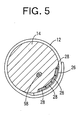
- Fig. 5 is a cross-section view showing the state in which the cuff 12 is wound around the upper arm 14. As shown in Fig. 5, the pressure-sensing elements 32 provided on the press surfaces 30 of the pressure-pulse-wave sensors 28 have respective different distances from the brachial artery 98 of the upper arm 14.
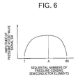
- Fig. 6 shows a relationship between the pressure-sensing elements 32 and respective amplitudes of the pressure-pulse-wave signals SM detected by the elements 32.
- the sequential numbers of the pressure-sensing elements 32 start with one of opposite ends of the array of elements 32 provided on the press surfaces 30.
- Respective amplitudes of pressure-pulse-wave signals SM detected by nearer pressure-sensing elements 32 to the brachial artery 98 are greater than those detected by remoter elements 32 from the artery 98. Therefore, the optimum-element selecting means 96 selects, as the optimum element A, one of the pressure-sensing elements 32 that provides a pressure-pulse-wave signal SM having a greater amplitude in the relationship shown in Fig. 6, most preferably, the element 32 that provides the signal SM having the greatest amplitude.
- a heart-sound extracting means 100 subjects the pressure-pulse-wave signal SM supplied from the optimum element A, to a digital filter, and thereby extracts, from the signal SM, a heart-sound component having frequencies in a prescribed frequency band corresponding to a frequency band generally possessed by heart sounds.
- the thus extracted heart sounds are displayed on the display device 80.
- the prescribed frequency band may range from 30 to 600 Hz.
- a main component of the pressure-pulse-wave signal SM is the pressure pulse wave BAP produced from the brachial artery 98.
- heart sounds which are produced when the valves of the heart are opened and closed propagate through the blood vessels. Therefore, the pressure-pulse-wave signal SM contains the heart-sound component.
- the heart sounds can be detected at the upper arm 14 by extracting, from the pressure-pulse-wave signal SM, a signal having frequencies in the frequency band generally had by heart sounds.
- a noise removing means 102 subjects the pressure-pulse-wave signal SM supplied from the optimum element A, to a digital filter, and thereby removes noise from the signal SM, so as to extract the pressure pulse wave BAP produced when the brachial artery 98 pulsates.
- the signal SM from which noise has been removed is displayed on the display device 80. Since the pressure pulse wave BAP is a heartbeat-synchronous wave, the noise removing means 102 removes, from the signal SM, a component having frequencies not lower than 50 Hz.
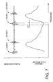
- Fig. 7 shows heart sounds extracted by the heart-sound extracting means 100, and a pressure pulse wave BAP freed of noise by the noise removing means 102.
- a pulse-wave-propagation-velocity-relating-information obtaining means 104 includes a time-difference determining means 106, and a pulse-wave-propagation-velocity determining means 108.
- the time-difference determining means 106 determines a timing when a prescribed periodic point of the heart sounds extracted by the heart-sound extracting means 100 is detected, and a timing when a prescribed periodic point of the pressure pulse wave BAP is detected, and determines a time difference DT (sec) between the two timings (i.e., a pulse-wave propagation time).
- the prescribed periodic point of the heart sounds may be a starting point (i.e., a rising point) of a first heart sound I, a peak point of a first heart sound I, a starting point of a second heart sound II, or a peak point of the second heart sound II.
- the prescribed periodic point of the pressure pulse wave BAP may be a rising point or a peak point of a heartbeat-synchronous pulse of the wave BAP.
- Fig. 7 shows a time difference DT between a rising point of a first heart sound I and a rising point of a corresponding heartbeat-synchronous pulse of a pressure pulse wave BAP.
- PWV L/DT
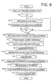
- Fig. 8 is a flow chart representing a control program according to which the control device 46 is operated, as shown in Fig. 4, to determine a pulse-wave propagation velocity PWV.
- the determination of pulse-wave propagation velocity PWV is carried out in a state in which the upper arm 14 is not pressed by the large cuff 18.
- Step S1 (hereinafter, "Step" is omitted) corresponding to the small-cuff-pressure control means 94, the control device 46 starts the air pump 56 and operates the pressure control valve 54, so that the pressing pressure P K2 of the small cuff 20 is kept at a considerably low pressure of, e.g., 40 mmHg.
- a content of a timer t is replaced with "0", so that the timer t is reset to zero and, at S3, the control device 46 outputs the switch signal SC to switch the multiplexer 60 and the EPROM 64 at a period sufficiently shorter than an average pulse period. Then, at S4, the control device 46 reads in the pressure-pulse-wave signal SM supplied from the multiplexer 60.
- the control device 46 judges whether a time indicated by a number counted by the timer t has reached a prescribed reading-in period T.
- the reading-in period T may be equal to an average pulse period, i.e., a length of one average heartbeat-synchronous pulse.
- control goes to S6 and S7 corresponding to the optimum-element selecting means 96.
- the control device 46 determines respective amplitudes of the respective pressure-pulse-wave signals SM which have been read in while S3, S4 and S5 are repeated.
- the control device 46 determines the greatest one of the respective amplitudes determined at S6, and determines, as the optimum element A, one of the pressure sensing elements 32 that provides the greatest amplitude.
- control goes to S8 corresponding to the heart-sound extracting means 100. More specifically described, at S8, the control device 46 subjects the pressure-pulse-wave signal SM detected by the optimum element A selected at S7, to a digital filter, so as to extract a component having frequencies of from 30 to 600 Hz. Thus, the heart-sound component is extracted from the pressure-pulse-wave signal SM.
- the control device 46 processes a waveform of the heart-sound component extracted at S8, so as to determine a prescribed periodic point on the waveform as one of two reference points to determine a pulse-wave propagation time DT. More specifically described, the waveform of the heart-sound component is subjected to a smoothing or differentiating process which is known as a useful technique to process a physical signal, and the thus processed waveform is further subjected to a squaring process. Thus, the amplitude of the waveform of heart sounds, measured from a baseline representing a signal level when no heart sounds are detected, is squared.
- the control device 46 determines, based on the waveform whose amplitude has been squared at S9, a starting point of a first heart sound I as the first reference point to determine the pulse-wave propagation time DT. Then, at S11 corresponding to the noise removing means 102, the control device 46 subjects the pressure-pulse-wave signal SM detected by the optimum element A, to a digital filter to remove a component having frequencies not lower than 50 Hz. Thus, a pressure pulse wave BAP free of noise is extracted from the pressure-pulse-wave sensor SM.
- the control device 46 determines, based on the pressure pulse wave BAP extracted at S11, a rising point of the wave BAP that corresponds to the starting point of the first heart sound I.
- the rising point of the wave BAP is the second reference point to determine the pulse-wave. propagation time DT.
- the control device 46 determines a time difference DT between the time when the starting point of the first heart sound I determined at S10 was detected, and the time when the rising point of the pressure pulse wave BAP determined at S12 was detected.
- the control device 46 determines a pulse-wave propagation velocity PWV by replacing the parameter DT of the expression (1) with the time difference DT determined at S13.
- the thus determined pulse-wave propagation velocity PWV is displayed on the display device 80.
- the control goes back to S2.
- heart sounds are continuously detected and pulse-wave propagation velocities PWV are continuously determined.
- the heart-sound extracting means 100 extracts the heart-sound component representing the heart sounds, from the pressure-pulse-wave signal SM provided by the pressure-pulse-wave sensor 28 worn on the upper arm 14.
- the heart sounds can be detected at a position distant from the chest.
- the optimum-element selecting means 96 selects, from the plurality of pressure-sensing semiconductor elements 32, the optimum element A that can detect, with the highest sensitivity, the pressure pulse wave BAP, and the heart-sound component is extracted from the pressure-pulse-wave signal SM provided by the optimum element A.
- heart sounds having a clear waveform can be detected.
- the pressure-pulse-wave 28 detects two sorts of heartbeat-synchronous signals, i.e.,. the heart sounds and the pressure pulse wave BAP, and the pulse-wave-propagation-velocity determining means 106 (S14) determines the pulse-wave propagation velocity PWV based on the heart sounds and the pressure pulse wave BAP.
- the single pressure-pulse-wave sensor 28 suffices for determining the pulse-wave propagation velocity PWV, and accordingly it can be easily worn on the patient.
- the pressure-pulse-wave sensor 28 when the cuff 12 is wound around the upper arm 14 to measure a blood pressure of a living subject, simultaneously the pressure-pulse-wave sensor 28 to detect the heart sounds is worn on the subject. Since the cuff 12 is adapted to be closely wound around a body portion of a living subject, that the cuff 12 is wound around the upper arm 14 means that the pressure-pulse-wave sensor 28 is appropriately worn on the upper arm 14.
- the pressure-pulse-wave sensor 28 is adapted to be worn on the upper arm 14.
- the sensor 28 may be adapted to be worn on a neck or a wrist.
- the heart-sound extracting means 100 comprises the digital filter, i.e., software.
- the extracting means 100 may comprise an analog filter which is provided by resistors, capacitors, etc.
- the illustrated physical-information obtaining apparatus 10 employs the four pressure-pulse-wave sensors 28 each of which includes the fifteen pressure-sensing semiconductor elements 32, i.e., the sixty pressure-sensing elements 32, in total, to detect the respective pressure-pulse-wave signals SM.
- the number of the pressure-sensing elements 32 is not limited to sixty, but may be one only.
- Each of the pressure-pulse-wave sensors 28 includes the pressure-sensing semiconductor elements 32 to detect the respective pressure pulse waves.
- a different type of pressure sensor e.g., a diaphragm-type pressure sensor that utilizes the change of resistance of a strain gauge, formed in a diaphragm, when the gauge is displaced by a pressure exerted thereto.
- the cuff-pulse -wave signal SW extracted by the high-pass filter 42 and the low-pass filter 48 from the first pressure signal SP 1 provided by the pressure sensor 34 also represents a pressure pulse wave BAP produced from the brachial artery 98. Therefore, the pressure sensor 34, the high-pass filter 42, and the low-pass filter 48 may be used as a pressure-pulse-wave sensor.
Landscapes
- Health & Medical Sciences (AREA)
- Life Sciences & Earth Sciences (AREA)
- Animal Behavior & Ethology (AREA)
- Veterinary Medicine (AREA)
- Heart & Thoracic Surgery (AREA)
- Medical Informatics (AREA)
- Molecular Biology (AREA)
- Surgery (AREA)
- Engineering & Computer Science (AREA)
- General Health & Medical Sciences (AREA)
- Public Health (AREA)
- Biomedical Technology (AREA)
- Hematology (AREA)
- Physics & Mathematics (AREA)
- Biophysics (AREA)
- Pathology (AREA)
- Cardiology (AREA)
- Physiology (AREA)
- Measuring Pulse, Heart Rate, Blood Pressure Or Blood Flow (AREA)
Applications Claiming Priority (2)
| Application Number | Priority Date | Filing Date | Title |
|---|---|---|---|
| JP2001030879 | 2001-02-07 | ||
| JP2001030879A JP2002224065A (ja) | 2001-02-07 | 2001-02-07 | 心音検出装置および心音検出方法 |
Publications (1)
| Publication Number | Publication Date |
|---|---|
| EP1230897A1 true EP1230897A1 (de) | 2002-08-14 |
Family
ID=18895036
Family Applications (1)
| Application Number | Title | Priority Date | Filing Date |
|---|---|---|---|
| EP01122004A Withdrawn EP1230897A1 (de) | 2001-02-07 | 2001-09-13 | Vorrichtung und Verfahren zur Herzgeräuschdetektion |
Country Status (3)
| Country | Link |
|---|---|
| US (1) | US20020107450A1 (de) |
| EP (1) | EP1230897A1 (de) |
| JP (1) | JP2002224065A (de) |
Cited By (2)
| Publication number | Priority date | Publication date | Assignee | Title |
|---|---|---|---|---|
| EP1518496A1 (de) * | 2003-09-25 | 2005-03-30 | Omron Healthcare Co., Ltd. | Pulswellenmessgerät |
| WO2017211869A1 (en) * | 2016-06-07 | 2017-12-14 | Viewcare Technologies 1 Aps | Method and system for measuring a central pulse wave velocity in a pregnant woman |
Families Citing this family (47)
| Publication number | Priority date | Publication date | Assignee | Title |
|---|---|---|---|---|
| US6527711B1 (en) | 1999-10-18 | 2003-03-04 | Bodymedia, Inc. | Wearable human physiological data sensors and reporting system therefor |
| US6453201B1 (en) | 1999-10-20 | 2002-09-17 | Cardiac Pacemakers, Inc. | Implantable medical device with voice responding and recording capacity |
| US7689437B1 (en) * | 2000-06-16 | 2010-03-30 | Bodymedia, Inc. | System for monitoring health, wellness and fitness |
| BRPI0414359A (pt) * | 2000-06-16 | 2006-11-14 | Bodymedia Inc | sistema para a monitoração e gerenciamento do peso corpóreo e demais condições psicológicas que abrangem um planejamento interativo e personalizado, intervenção e capacidade de formular relatórios |
| US20060122474A1 (en) | 2000-06-16 | 2006-06-08 | Bodymedia, Inc. | Apparatus for monitoring health, wellness and fitness |
| US7261690B2 (en) * | 2000-06-16 | 2007-08-28 | Bodymedia, Inc. | Apparatus for monitoring health, wellness and fitness |
| ES2260245T3 (es) * | 2000-06-23 | 2006-11-01 | Bodymedia, Inc. | Sistema para controlar la salud, el bienestar y el ejercicio. |
| US7052466B2 (en) | 2001-04-11 | 2006-05-30 | Cardiac Pacemakers, Inc. | Apparatus and method for outputting heart sounds |
| WO2003061468A1 (en) * | 2002-01-23 | 2003-07-31 | Bang & Olufsen Medicom A/S | A blood pressure measuring device with a cuff of two openable concave shell parts |
| US7137955B2 (en) * | 2002-04-19 | 2006-11-21 | Omron Healthcare Co., Ltd. | Methods and systems for distal recording of phonocardiographic signals |
| US7020508B2 (en) * | 2002-08-22 | 2006-03-28 | Bodymedia, Inc. | Apparatus for detecting human physiological and contextual information |
| AU2003275491A1 (en) | 2002-10-09 | 2004-05-04 | Bodymedia, Inc. | Method and apparatus for auto journaling of continuous or discrete body states utilizing physiological and/or contextual parameters |
| US7972275B2 (en) | 2002-12-30 | 2011-07-05 | Cardiac Pacemakers, Inc. | Method and apparatus for monitoring of diastolic hemodynamics |
| JP3667327B2 (ja) * | 2003-04-21 | 2005-07-06 | コーリンメディカルテクノロジー株式会社 | 携帯型生体情報測定装置 |
| US7182738B2 (en) | 2003-04-23 | 2007-02-27 | Marctec, Llc | Patient monitoring apparatus and method for orthosis and other devices |
| EP2319410A1 (de) | 2003-09-12 | 2011-05-11 | BodyMedia, Inc. | Vorrichtung zur Messung von Herzparametern |
| US7248923B2 (en) | 2003-11-06 | 2007-07-24 | Cardiac Pacemakers, Inc. | Dual-use sensor for rate responsive pacing and heart sound monitoring |
| CA2560323C (en) | 2004-03-22 | 2014-01-07 | Bodymedia, Inc. | Non-invasive temperature monitoring device |
| US7559901B2 (en) | 2004-07-28 | 2009-07-14 | Cardiac Pacemakers, Inc. | Determining a patient's posture from mechanical vibrations of the heart |
| US7662104B2 (en) | 2005-01-18 | 2010-02-16 | Cardiac Pacemakers, Inc. | Method for correction of posture dependence on heart sounds |
| US7404802B2 (en) * | 2005-05-05 | 2008-07-29 | Cardiac Pacemakers, Inc. | Trending of systolic murmur intensity for monitoring cardiac disease with implantable device |
| US7424321B2 (en) | 2005-05-24 | 2008-09-09 | Cardiac Pacemakers, Inc. | Systems and methods for multi-axis cardiac vibration measurements |
| US8972002B2 (en) | 2005-06-01 | 2015-03-03 | Cardiac Pacemakers, Inc. | Remote closed-loop titration of decongestive therapy for the treatment of advanced heart failure |
| US7670298B2 (en) | 2005-06-01 | 2010-03-02 | Cardiac Pacemakers, Inc. | Sensing rate of change of pressure in the left ventricle with an implanted device |
| US7922669B2 (en) | 2005-06-08 | 2011-04-12 | Cardiac Pacemakers, Inc. | Ischemia detection using a heart sound sensor |
| US7585279B2 (en) | 2005-07-26 | 2009-09-08 | Cardiac Pacemakers, Inc. | Managing preload reserve by tracking the ventricular operating point with heart sounds |
| US7634309B2 (en) * | 2005-08-19 | 2009-12-15 | Cardiac Pacemakers, Inc. | Tracking progression of congestive heart failure via a force-frequency relationship |
| US8108034B2 (en) | 2005-11-28 | 2012-01-31 | Cardiac Pacemakers, Inc. | Systems and methods for valvular regurgitation detection |
| US8920343B2 (en) | 2006-03-23 | 2014-12-30 | Michael Edward Sabatino | Apparatus for acquiring and processing of physiological auditory signals |
| US7780606B2 (en) | 2006-03-29 | 2010-08-24 | Cardiac Pacemakers, Inc. | Hemodynamic stability assessment based on heart sounds |
| US8000780B2 (en) | 2006-06-27 | 2011-08-16 | Cardiac Pacemakers, Inc. | Detection of myocardial ischemia from the time sequence of implanted sensor measurements |
| US20080119749A1 (en) * | 2006-11-20 | 2008-05-22 | Cardiac Pacemakers, Inc. | Respiration-synchronized heart sound trending |
| US8096954B2 (en) | 2006-11-29 | 2012-01-17 | Cardiac Pacemakers, Inc. | Adaptive sampling of heart sounds |
| US7736319B2 (en) | 2007-01-19 | 2010-06-15 | Cardiac Pacemakers, Inc. | Ischemia detection using heart sound timing |
| US20090006458A1 (en) | 2007-02-16 | 2009-01-01 | Stivoric John M | Life bytes |
| US7853327B2 (en) | 2007-04-17 | 2010-12-14 | Cardiac Pacemakers, Inc. | Heart sound tracking system and method |
| JP5230161B2 (ja) * | 2007-10-04 | 2013-07-10 | フクダ電子株式会社 | 心機図検査装置 |
| RU2404705C2 (ru) * | 2008-12-12 | 2010-11-27 | Владимир Федорович Романовский | Способ измерения артериального давления и устройство для его осуществления |
| KR101632307B1 (ko) | 2009-05-27 | 2016-06-21 | 삼성전자주식회사 | 혈압 추정 방법 및 장치 |
| KR101081659B1 (ko) * | 2010-01-29 | 2011-11-09 | 이병훈 | 병명이 표시되는 혈압기 |
| JP5766569B2 (ja) * | 2011-09-27 | 2015-08-19 | 株式会社東芝 | 脈波伝播速度計測装置 |
| CA2931274A1 (en) | 2014-01-21 | 2015-07-30 | California Institute Of Technology | Portable electronic hemodynamic sensor systems |
| EP3026523B1 (de) | 2014-11-28 | 2019-08-28 | Nokia Technologies OY | Verfahren und Vorrichtung zur Hautkontaktierung mit Sensoreinrichtung |
| DE102015000328A1 (de) * | 2015-01-09 | 2016-07-14 | Fachhochschule Lübeck | Verfahren und Vorrichtung zur Messung der Pulswellengeschwindigkeit einer Messperson |
| JP6594135B2 (ja) * | 2015-09-16 | 2019-10-23 | オムロンヘルスケア株式会社 | 生体情報測定装置、生体情報測定方法、及び生体情報測定プログラム |
| US20240108303A1 (en) * | 2022-09-23 | 2024-04-04 | California Institute Of Technology | Method for cardiac auscultation using blood pressure cuff |
| US20250352077A1 (en) * | 2024-05-14 | 2025-11-20 | K-Jump Health Co., Ltd. | Blood pressure measuring device capable of measuring meridians |
Citations (5)
| Publication number | Priority date | Publication date | Assignee | Title |
|---|---|---|---|---|
| US3978848A (en) * | 1975-01-09 | 1976-09-07 | Filac Corporation | Monitoring apparatus and method for blood pressure and heart rate |
| US4248241A (en) * | 1979-08-17 | 1981-02-03 | Tacchi Ernest J | Patient monitoring apparatus |
| FR2535964A1 (fr) * | 1982-11-17 | 1984-05-18 | Mesnard Guy | Appareillage de mesure, de traitement, de stockage et d'affichage de signaux biomedicaux |
| US5406953A (en) * | 1991-06-24 | 1995-04-18 | Bui; Hoanh | Apparatus for measurement of blood pressure with electronic amplification system for Karotkoff sounds |
| US5957866A (en) * | 1995-07-03 | 1999-09-28 | University Technology Corporation | Apparatus and methods for analyzing body sounds |
Family Cites Families (7)
| Publication number | Priority date | Publication date | Assignee | Title |
|---|---|---|---|---|
| JPS52108684A (en) * | 1976-03-09 | 1977-09-12 | Nippon Roudou Bunka Kiyoukai | Device for measuring aortic pulse wave velocity |
| JPS6227922A (ja) * | 1985-07-31 | 1987-02-05 | 日本光電工業株式会社 | 自動血圧測定装置 |
| US4802488A (en) * | 1986-11-06 | 1989-02-07 | Sri International | Blood pressure monitoring method and apparatus |
| JPH082351B2 (ja) * | 1987-05-27 | 1996-01-17 | コ−リン電子株式会社 | 脈波検出装置 |
| JPH069618B2 (ja) * | 1989-02-01 | 1994-02-09 | 株式会社アドバンス | 電気刺激装置 |
| JPH08675U (ja) * | 1995-02-06 | 1996-04-23 | 株式会社アドバンス | 電気刺激装置 |
| JPH10295657A (ja) * | 1997-04-24 | 1998-11-10 | Matsushita Electric Ind Co Ltd | 血圧測定装置 |
-
2001
- 2001-02-07 JP JP2001030879A patent/JP2002224065A/ja active Pending
- 2001-08-31 US US09/942,865 patent/US20020107450A1/en not_active Abandoned
- 2001-09-13 EP EP01122004A patent/EP1230897A1/de not_active Withdrawn
Patent Citations (5)
| Publication number | Priority date | Publication date | Assignee | Title |
|---|---|---|---|---|
| US3978848A (en) * | 1975-01-09 | 1976-09-07 | Filac Corporation | Monitoring apparatus and method for blood pressure and heart rate |
| US4248241A (en) * | 1979-08-17 | 1981-02-03 | Tacchi Ernest J | Patient monitoring apparatus |
| FR2535964A1 (fr) * | 1982-11-17 | 1984-05-18 | Mesnard Guy | Appareillage de mesure, de traitement, de stockage et d'affichage de signaux biomedicaux |
| US5406953A (en) * | 1991-06-24 | 1995-04-18 | Bui; Hoanh | Apparatus for measurement of blood pressure with electronic amplification system for Karotkoff sounds |
| US5957866A (en) * | 1995-07-03 | 1999-09-28 | University Technology Corporation | Apparatus and methods for analyzing body sounds |
Cited By (5)
| Publication number | Priority date | Publication date | Assignee | Title |
|---|---|---|---|---|
| EP1518496A1 (de) * | 2003-09-25 | 2005-03-30 | Omron Healthcare Co., Ltd. | Pulswellenmessgerät |
| CN100370947C (zh) * | 2003-09-25 | 2008-02-27 | 欧姆龙健康医疗事业株式会社 | 脉搏波计测装置 |
| US7510530B2 (en) | 2003-09-25 | 2009-03-31 | Omron Healthcare Co., Ltd. | Pulse wave measuring apparatus |
| WO2017211869A1 (en) * | 2016-06-07 | 2017-12-14 | Viewcare Technologies 1 Aps | Method and system for measuring a central pulse wave velocity in a pregnant woman |
| US11617563B2 (en) | 2016-06-07 | 2023-04-04 | Viewcare Technologies 1 Aps | Method and system for measuring a central pulse wave velocity in a pregnant woman |
Also Published As
| Publication number | Publication date |
|---|---|
| JP2002224065A (ja) | 2002-08-13 |
| US20020107450A1 (en) | 2002-08-08 |
Similar Documents
| Publication | Publication Date | Title |
|---|---|---|
| US7022084B2 (en) | Heart-sound detecting apparatus and heart-sound detecting method | |
| US20020107450A1 (en) | Heart-sound detecting apparatus and heart-sound detecting method | |
| US6824519B2 (en) | Heart-sound detecting apparatus | |
| US6610017B2 (en) | Continuous blood-pressure monitoring apparatus | |
| US6475155B2 (en) | Pulse-wave-propagation-relating information obtaining apparatus and arterial-bifurcate-portion determining apparatus | |
| US6428482B1 (en) | Central-artery-pressure-waveform estimating apparatus | |
| US6869403B2 (en) | Blood-pressure determining apparatus | |
| US6652465B2 (en) | Blood-pressure measurement apparatus capable of heart function assessment | |
| US6645156B2 (en) | Continuous blood-pressure monitoring apparatus | |
| US6602198B2 (en) | Automatic blood-pressure measuring apparatus | |
| EP1332715A2 (de) | Arterioskleroseuntersuchungsapparat | |
| US6346083B1 (en) | Blood-pressure measuring device | |
| JPH0311219B2 (de) | ||
| US6669645B2 (en) | Autonomic-nerve-function evaluating apparatus | |
| US20120029366A1 (en) | Blood pressure detection apparatus and blood pressure detection method | |
| US6561985B2 (en) | Automatic blood-pressure measuring apparatus | |
| US6808497B2 (en) | Blood-pressure measuring apparatus and inferior-and-superior-limb blood-pressure-index measuring apparatus | |
| EP1327415A1 (de) | Gerät zur Beurteilung von Arteriosklerose | |
| EP1302165A1 (de) | Apparat zur Ermittlung eines charakteristischen Punktes von Pulswellen, und Apparat zur Ermittlung von pulswellengeschwindigkeitsrelevanter Information unter Verwendung des Apparates zur Ermittlung eines charakteristischen Punktes von Pulswellen | |
| US20040171941A1 (en) | Blood flow amount estimating apparatus | |
| US6730039B2 (en) | Arteriosclerosis-degree evaluating apparatus | |
| JP2516634B2 (ja) | 血圧連続測定装置 | |
| JPH0362087B2 (de) |
Legal Events
| Date | Code | Title | Description |
|---|---|---|---|
| PUAI | Public reference made under article 153(3) epc to a published international application that has entered the european phase |
Free format text: ORIGINAL CODE: 0009012 |
|
| AK | Designated contracting states |
Kind code of ref document: A1 Designated state(s): AT BE CH CY DE DK ES FI FR GB GR IE IT LI LU MC NL PT SE TR |
|
| AX | Request for extension of the european patent |
Free format text: AL;LT;LV;MK;RO;SI |
|
| 17P | Request for examination filed |
Effective date: 20030128 |
|
| AKX | Designation fees paid |
Designated state(s): DE FR GB |
|
| 17Q | First examination report despatched |
Effective date: 20031014 |
|
| STAA | Information on the status of an ep patent application or granted ep patent |
Free format text: STATUS: THE APPLICATION IS DEEMED TO BE WITHDRAWN |
|
| 18D | Application deemed to be withdrawn |
Effective date: 20040225 |