EP1230943A2 - Cartouche absorbante de dioxyde de carbone avec carter de rétention d'humidité du gaz respiratoire - Google Patents
Cartouche absorbante de dioxyde de carbone avec carter de rétention d'humidité du gaz respiratoire Download PDFInfo
- Publication number
- EP1230943A2 EP1230943A2 EP02250826A EP02250826A EP1230943A2 EP 1230943 A2 EP1230943 A2 EP 1230943A2 EP 02250826 A EP02250826 A EP 02250826A EP 02250826 A EP02250826 A EP 02250826A EP 1230943 A2 EP1230943 A2 EP 1230943A2
- Authority
- EP
- European Patent Office
- Prior art keywords
- canister
- container
- sump
- breathing
- valve
- Prior art date
- Legal status (The legal status is an assumption and is not a legal conclusion. Google has not performed a legal analysis and makes no representation as to the accuracy of the status listed.)
- Granted
Links
Images


Classifications
-
- A—HUMAN NECESSITIES
- A61—MEDICAL OR VETERINARY SCIENCE; HYGIENE
- A61M—DEVICES FOR INTRODUCING MEDIA INTO, OR ONTO, THE BODY; DEVICES FOR TRANSDUCING BODY MEDIA OR FOR TAKING MEDIA FROM THE BODY; DEVICES FOR PRODUCING OR ENDING SLEEP OR STUPOR
- A61M16/00—Devices for influencing the respiratory system of patients by gas treatment, e.g. ventilators; Tracheal tubes
- A61M16/08—Bellows; Connecting tubes ; Water traps; Patient circuits
- A61M16/0808—Condensation traps
-
- A—HUMAN NECESSITIES
- A61—MEDICAL OR VETERINARY SCIENCE; HYGIENE
- A61M—DEVICES FOR INTRODUCING MEDIA INTO, OR ONTO, THE BODY; DEVICES FOR TRANSDUCING BODY MEDIA OR FOR TAKING MEDIA FROM THE BODY; DEVICES FOR PRODUCING OR ENDING SLEEP OR STUPOR
- A61M16/00—Devices for influencing the respiratory system of patients by gas treatment, e.g. ventilators; Tracheal tubes
- A61M16/22—Carbon dioxide-absorbing devices ; Other means for removing carbon dioxide
Definitions
- This invention relates to patient ventilator systems in which breathing gas is circulated through a carbon dioxide absorber canister, and more particularly, to an improved carbon dioxide absorber canister having an integral moisture sump.
- Prior art ventilator systems have utilized various sumps to trap and remove condensate.
- the carbon dioxide absorbing canister itself has often been relied on as a common sump although the canister's primary function is removing carbon dioxide from the patient's expired breathing gases.
- the canister inlet structure located upstream of the canister itself, including the expiratory check valve of the breathing system, is inherently difficult to maintain free of excessive condensate.
- the periodic actuation of a valve by a patient attendee was necessary for removal of condensate in this area.
- sumps separate stand-alone sumps have been employed specifically to drain the moisture from problematic areas. These sumps allowed the patient's attendees to view the collected moisture through a window or a transparent container so that the attendee could empty the collected moisture before the sump overflowed into the breathing circuit.
- both the valve actuation mechanisms and the stand alone sump arrangements require extensive vigilance on the part of the patient's attendees.
- This demand on the attendees only adds to the already numerous ventilator servicing requirements which include removing and replacing spent carbon dioxide absorbing materials from the canister, ensuring proper composition of ventilator gases, maintaining desired gas volumes and pressures in the breathing circuit, and maintaining optimum humidity in inspiratory breathing gases.
- This invention is a carbon dioxide absorber canister with an integral moisture sump.
- the moisture sump collects condensate from areas of a breathing circuit that are difficult to drain to a common sump, such as the carbon dioxide absorber canister itself.
- the moisture sump found in the present invention may be integrally formed into the structure of the carbon dioxide absorber canister, the canister including a hollow container adapted to contain a carbon dioxide absorbing material.
- the moisture sump includes a reservoir chamber for accepting collected condensate.
- the reservoir chamber may be arcuately-shaped with an upwardly facing entrance formed by surrounding walls.
- the entrance to the reservoir chamber offers a sealing surface for pneumatically sealing with the breathing circuit. This pneumatic seal is arranged so that the seal is accomplished by attachment of the carbon dioxide absorber canister to the patient ventilator system and is broken when the canister is subsequently removed from the system.
- the moisture sump is adapted to collect condensate from breathing circuit areas proximate the inlet and outlet ports of the canister.
- Such areas include the inlet structures and outlet structures located in the patient ventilator system, specifically, the expiratory check valve and the inspiratory check valve.
- the expiratory check valve is known to be a particularly troublesome area from which to drain condensed moisture.
- the moisture sump's reservoir chamber may have a volume sized to accommodate the maximum amount of condensate collected in a given time interval, such as the life expectancy of the carbon dioxide absorbing material contained within the hollow container of the canister. Therefore, the patient's attendees are not required to monitor the moisture buildup in the moisture sump independently of other tasks. Removal of the carbon dioxide absorber canister from the breathing circuit automatically ensures that the condensed moisture contained in the integral sump is also removed.
- Fig. 1 is an overview of a patient ventilator breathing circuit 10 showing elements of the circuit as distinct functional blocks.
- Exhaled breathing gases initially travel from the patient through a flow sensor 12.
- Flow sensor 12 provides output information to a patient attendee regarding flow characteristics of the exhaled gases.
- Expired breathing gases then flow to an expiration valve structure 16.
- moisture is separated from the expired breathing gases and drains into moisture well or condensate sump 14.
- the breathing gases then pass through the expiratory check valve 17 contained in the structure 16 associated with a CO 2 absorber (canister) 18.
- Mechanical ventilator, or manually operated flexible bag, 20 is connected to the flow path for the breathing gases downstream of the expiratory check valve 17 to drive the re-circulating breathing gases through CO 2 absorber 18.
- CO 2 absorber 18 CO 2 gas is removed by contact with a CO 2 removing material, such as soda lime.
- Fig. 1 the functional blocks representing condensate well 14 and carbon dioxide absorber 18 are interconnected to graphically represent the integral design of these components found in the present invention. Also, and as shown in diagrammatic form in Fig. 1, moisture (water) carried by the breathing gases is removed from the gases before the gases pass through the expiratory check valve 17, thereby avoiding an excessive build up of moisture that could interfere with the operation of the valve 17. Further, removing moisture from the breathing gases upstream of the expiratory check valve 17 is advantageous in limiting or precluding moisture from entering ventilator/bag 20.
- the expiratory gas exits CO 2 absorber 18 and fresh anesthesia gases, block 22, are added if necessary.
- the gases flow through an inspiratory check valve 23 located within an inspiratory valve structure 24 before being returned to the patient. Between the inspiratory check valve 24 and the patient, a pressure sensor 26, oxygen sensor 28, flow sensor 30, and other apparatus may be present.
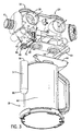
- Fig. 2 depicts a patient ventilator apparatus 32 including a CO 2 absorber canister 18 with an integral moisture sump 14 according to the present invention.
- Fig. 3 shows an exploded perspective view of the apparatus of Fig. 2.
- Fig. 4 shows a cross-sectional view of the canister 18 with sump 14 of Figs 2 and 3.
- a patient ventilator apparatus 32 includes a flow sensor module 36 partially enclosing a ventilator 20, an expiratory valve structure 16 and an inspiratory valve structure 24.
- Expiratory valve structure 16 includes an expiratory valve inlet 34 seen protruding from ventilator housing 36 in Fig. 2.
- Expiratory valve inlet 34 communicates with the expiratory valve body 38 located within flow sensor module 36.
- Expiratory valve body 38 communicates with an expiratory valve outlet 40 located on the underside of the ventilator apparatus 32.
- Fig. 4 illustrates that between inlet 34 and outlet 40, expiratory valve body 38 contains valve disk 41 mounted on valve seat 43 to control the passage of gas through the valve body 38.
- the expiratory valve structure 16 communicates with ventilator 20 through ventilator port 41.
- Ventilator port 41 is located downstream of the point in expiratory valve body 38, at which moisture is removed from the expiration gases. Condensed moisture reaching ventilator 20 is thus largely reduced.
- expiratory valve body 38 includes an expiratory valve drain 42 adapted to collect and route condensed moisture away from the expiratory valve body 38. Condensate in the breathing circuit enters expiratory valve body 38 through valve inlet 34 and, unable to follow the upwardly leading path of the breathing gases shown by arrow a in Fig. 4, will drain to a lower portion 78 of the expiratory valve body 38. Condensate collected at the lower portion 78 then enters valve drain 42 and travels downward to reservoir chamber 80 of moisture sump 14. Reservoir chamber 80 is formed by sump wall 82 which extends from an upper entrance 84 downward to transition into a bottom 86. Lower portion 48 of drain tube 42 forms a pneumatic seal with reservoir chamber 80 through O-ring 46.
- the preferred embodiment of the invention utilizes an arcuately-shaped reservoir chamber 80 formed by sump wall 82 which is integral with container wall 88 as shown in Figs. 2-4. However, reservoir chamber 80 and container chamber 90 are physically isolated from each other, as shown in Fig. 4.
- Container body 44 and sump 14 are preferably molded as a single unit. Suitable materials may include polysulfones with polyphenyl sulfone being preferred since these materials can withstand autoclaving. Polypropylene would also be a suitable material for canister construction.
- Expiratory valve outlet 40 forms a pneumatic seal with a canister inlet port 52 located on a top 54 of hollow container body 44. Expiratory gases exiting valve outlet 40 are conveyed in the direction of arrow b to container body 44 where they interact with a CO 2 absorbing material contained therein.
- the CO 2 absorbing material may be any material suitable for removing CO 2 from breathing gas. Soda lime is the preferred material.
- the breathing gases exit hollow container body 44 in the direction of arrow c through a canister outlet port 56 located on top 54 of container body 44.
- An inspiratory valve inlet 58 forms a pneumatic seal with the canister outlet port 56 and carries the breathing gases upward to the inspiratory valve body 60 (arrow d ).
- Inspiratory valve body 60 is equipped with a gas flow controlling valve disk 61 and seat 63, and an inspiratory valve outlet 62 which is in communication with subsequent elements of the breathing circuit.
- a fresh breathing gas port 64 communicates with inspiratory valve body 60 so that fresh breathing gases may be introduced into the breathing circuit if so desired by patient attendees.
- Canister 18 with integral sump 14 is secured to the expiratory valve outlet 40, expiratory valve moisture drain 42, and inspiratory valve inlet 58 through latches 66 located on top 54 of the hollow container body 44 which opposingly engage fixed latch receiving members 68 and movable-type latch receiving members 70.
- Movable type latch receiving members 70 are located on a latch actuator mechanism 72 which includes a latch actuator 74.
- the latch actuator 74 may be operated by a patient attendee to disengage the movable members 70 from the latches 66 to break the pneumatic seals between valves 16, 24, drain 42 and the carbon dioxide absorber canister 18 and moisture sump 14.
- the canister 18 with sump 14 may be reinstalled via the latching mechanism 72 to reestablish the pneumatic seals and consequently direct the expiratory gases of the breathing circuit past the moisture sump 14 and through container body 44.
- the container body 44 is adapted to contain an amount of CO 2 absorbing material, suitable for removing CO 2 from a given volume of breathing gases.
- the volume of the reservoir chamber 80 of sump 14 is appropriately sized to accommodate the maximum amount of condensate produced from the given volume. Therefore, a patient attendee need not be burdened with checking and removing/replacing a moisture sump separate from removing and replacing a CO 2 absorber canister.
- the integrated moisture sump 14 acts as a trap for condensed moisture formed before expired gases reach canister 18.
- the invention ensures that not only the expiratory valve 16 remains free of condensed moisture but that excessive moisture does not build up in the container chamber 90 of the canister 18. This improvement allows for less erratic response of the expiratory valve 16 as well as increased life and efficiency of the CO 2 absorbing material.
- Fig. 5 depicts an alternative embodiment of the invention.
- Figs. 1-4 show a single sump 14 on canister 18.
- a second moisture sump 92 provided on canister 18 to collect condensed moisture from an inspiratory valve drain (not shown) is alternately provided.
- the second moisture sump 92 shown in this embodiment resembles the first moisture sump 14 and appropriate modifications are made to canister 18 and valve structures 16 and 24.
Landscapes
- Health & Medical Sciences (AREA)
- Emergency Medicine (AREA)
- Pulmonology (AREA)
- Engineering & Computer Science (AREA)
- Anesthesiology (AREA)
- Biomedical Technology (AREA)
- Heart & Thoracic Surgery (AREA)
- Hematology (AREA)
- Life Sciences & Earth Sciences (AREA)
- Animal Behavior & Ethology (AREA)
- General Health & Medical Sciences (AREA)
- Public Health (AREA)
- Veterinary Medicine (AREA)
- Respiratory Apparatuses And Protective Means (AREA)
- Measurement Of The Respiration, Hearing Ability, Form, And Blood Characteristics Of Living Organisms (AREA)
- Devices For Medical Bathing And Washing (AREA)
Applications Claiming Priority (2)
| Application Number | Priority Date | Filing Date | Title |
|---|---|---|---|
| US09/780,262 US6619289B1 (en) | 2001-02-09 | 2001-02-09 | Carbon dioxide absorber canister with breathing gas moisture sump |
| US780262 | 2001-02-09 |
Publications (3)
| Publication Number | Publication Date |
|---|---|
| EP1230943A2 true EP1230943A2 (fr) | 2002-08-14 |
| EP1230943A3 EP1230943A3 (fr) | 2002-09-18 |
| EP1230943B1 EP1230943B1 (fr) | 2004-06-09 |
Family
ID=25119089
Family Applications (1)
| Application Number | Title | Priority Date | Filing Date |
|---|---|---|---|
| EP02250826A Expired - Lifetime EP1230943B1 (fr) | 2001-02-09 | 2002-02-07 | Cartouche absorbante de dioxyde de carbone avec carter de rétention d'humidité du gaz respiratoire |
Country Status (4)
| Country | Link |
|---|---|
| US (1) | US6619289B1 (fr) |
| EP (1) | EP1230943B1 (fr) |
| DE (1) | DE60200590T2 (fr) |
| ES (1) | ES2224025T3 (fr) |
Cited By (8)
| Publication number | Priority date | Publication date | Assignee | Title |
|---|---|---|---|---|
| FR2869235A1 (fr) * | 2004-04-24 | 2005-10-28 | Draeger Medical Ag | Dispositif comprenant un systeme respiratoire d'anesthesie et un absorbeur |
| EP1712246A1 (fr) | 2005-04-13 | 2006-10-18 | The General Electric Company | Dispositif de fixation d'une cartouche absorbante de dioxyde de carbone |
| EP2586482A1 (fr) * | 2011-10-24 | 2013-05-01 | General Electric Company | Ensemble de boîtier avec une substance pour éliminer d'un composant indésirable du gaz respiratoire d'un flux de gaz respiratoire et agencement pour ventiler les poumons d'un sujet |
| CN104248794A (zh) * | 2014-10-17 | 2014-12-31 | 深圳市百格医疗技术有限公司 | 二氧化碳吸收罐安装装置 |
| US9199050B2 (en) | 2012-04-30 | 2015-12-01 | Carefusion Corporation | Arrangement and method for guiding expired respiratory gas flow using gas routing device |
| WO2019075756A1 (fr) * | 2017-10-20 | 2019-04-25 | 深圳迈瑞生物医疗电子股份有限公司 | Machine d'anesthésie et son dispositif de drainage de circuit |
| EP2780067B1 (fr) * | 2011-11-18 | 2021-05-12 | Colin Dunlop | Circuit anesthésique à récyclage du gaz exhalé |
| EP3320942B1 (fr) | 2007-10-24 | 2023-03-22 | Drägerwerk AG & Co. KGaA | Absorbeur jetable disposant d'un adaptateur et d'un joint à lèvre |
Families Citing this family (44)
| Publication number | Priority date | Publication date | Assignee | Title |
|---|---|---|---|---|
| FR2858236B1 (fr) | 2003-07-29 | 2006-04-28 | Airox | Dispositif et procede de fourniture de gaz respiratoire en pression ou en volume |
| BR0305789B1 (pt) * | 2003-11-17 | 2013-10-01 | sistema absorvedor de diàxido de carbono | |
| US8028438B2 (en) * | 2004-07-02 | 2011-10-04 | Aqualizer, Llc | Moisture condensation control system |
| GB0425782D0 (en) * | 2004-11-24 | 2004-12-22 | Intersurgical Ltd | Improvements relating to respiratory circuits |
| DE102007025808B3 (de) * | 2007-06-02 | 2008-10-02 | Dräger Medical AG & Co. KG | Anschlusskopf für einen Absorber eines Narkoseatemsystems |
| CN101376040B (zh) * | 2007-08-31 | 2012-06-27 | 深圳迈瑞生物医疗电子股份有限公司 | 二氧化碳吸收罐安装装置 |
| DE102007051166A1 (de) * | 2007-10-25 | 2009-04-30 | P.P.W. Kontex Krzysztof Kondratowicz | Anästhesiegerät mit Atemgasumlauf |
| US8457706B2 (en) | 2008-05-16 | 2013-06-04 | Covidien Lp | Estimation of a physiological parameter using a neural network |
| US8302602B2 (en) | 2008-09-30 | 2012-11-06 | Nellcor Puritan Bennett Llc | Breathing assistance system with multiple pressure sensors |
| US20100192947A1 (en) * | 2009-02-04 | 2010-08-05 | Jeff Mandel | Anesthetic delivery system and methods of use |
| US8434479B2 (en) | 2009-02-27 | 2013-05-07 | Covidien Lp | Flow rate compensation for transient thermal response of hot-wire anemometers |
| US8439037B2 (en) | 2009-12-01 | 2013-05-14 | Covidien Lp | Exhalation valve assembly with integrated filter and flow sensor |
| US8439036B2 (en) | 2009-12-01 | 2013-05-14 | Covidien Lp | Exhalation valve assembly with integral flow sensor |
| US8469030B2 (en) | 2009-12-01 | 2013-06-25 | Covidien Lp | Exhalation valve assembly with selectable contagious/non-contagious latch |
| US8469031B2 (en) | 2009-12-01 | 2013-06-25 | Covidien Lp | Exhalation valve assembly with integrated filter |
| USD655405S1 (en) | 2010-04-27 | 2012-03-06 | Nellcor Puritan Bennett Llc | Filter and valve body for an exhalation module |
| USD655809S1 (en) | 2010-04-27 | 2012-03-13 | Nellcor Puritan Bennett Llc | Valve body with integral flow meter for an exhalation module |
| USD653749S1 (en) | 2010-04-27 | 2012-02-07 | Nellcor Puritan Bennett Llc | Exhalation module filter body |
| US8770191B2 (en) | 2011-01-07 | 2014-07-08 | General Electric Company | System and method for providing mechanical ventilation support to a patient |
| US9233218B2 (en) | 2011-01-10 | 2016-01-12 | General Electric Comapny | System and method of controlling the delivery of medical gases to a patient |
| US8770192B2 (en) | 2011-01-10 | 2014-07-08 | General Electric Company | System and method of preventing the delivery of hypoxic gases to a patient |
| EP2491997B1 (fr) * | 2011-02-25 | 2017-05-10 | CareFusion Corporation | Boîtier pour une substance solide ou fluide pour éliminer un composant indésirable du gaz respiratoire d'un flux de gaz respiratoire et agencement pour ventiler les poumons d'un sujet |
| US9629971B2 (en) | 2011-04-29 | 2017-04-25 | Covidien Lp | Methods and systems for exhalation control and trajectory optimization |
| US8992672B2 (en) | 2011-06-27 | 2015-03-31 | Carefusion Corporation | Housing and housing assembly for substance removing an undesired respiratory gas component of a respiratory gas flow and an arrangement for ventilating lungs of a subject |
| US9364624B2 (en) | 2011-12-07 | 2016-06-14 | Covidien Lp | Methods and systems for adaptive base flow |
| US9498589B2 (en) | 2011-12-31 | 2016-11-22 | Covidien Lp | Methods and systems for adaptive base flow and leak compensation |
| US9144658B2 (en) | 2012-04-30 | 2015-09-29 | Covidien Lp | Minimizing imposed expiratory resistance of mechanical ventilator by optimizing exhalation valve control |
| USD731049S1 (en) | 2013-03-05 | 2015-06-02 | Covidien Lp | EVQ housing of an exhalation module |
| USD736905S1 (en) | 2013-03-08 | 2015-08-18 | Covidien Lp | Exhalation module EVQ housing |
| USD701601S1 (en) | 2013-03-08 | 2014-03-25 | Covidien Lp | Condensate vial of an exhalation module |
| USD731065S1 (en) | 2013-03-08 | 2015-06-02 | Covidien Lp | EVQ pressure sensor filter of an exhalation module |
| USD692556S1 (en) | 2013-03-08 | 2013-10-29 | Covidien Lp | Expiratory filter body of an exhalation module |
| USD744095S1 (en) | 2013-03-08 | 2015-11-24 | Covidien Lp | Exhalation module EVQ internal flow sensor |
| USD693001S1 (en) | 2013-03-08 | 2013-11-05 | Covidien Lp | Neonate expiratory filter assembly of an exhalation module |
| USD731048S1 (en) | 2013-03-08 | 2015-06-02 | Covidien Lp | EVQ diaphragm of an exhalation module |
| US9950135B2 (en) | 2013-03-15 | 2018-04-24 | Covidien Lp | Maintaining an exhalation valve sensor assembly |
| BE1023363B1 (nl) * | 2014-08-26 | 2017-02-20 | Medec Benelux Nv | Aansluiting en sluitsysteem van ademkalkbeker op beademingssysteem |
| CN204798550U (zh) * | 2015-04-08 | 2015-11-25 | Ge医疗系统环球技术有限公司 | 麻醉机呼吸系统 |
| USD775345S1 (en) | 2015-04-10 | 2016-12-27 | Covidien Lp | Ventilator console |
| US11253669B2 (en) * | 2019-05-07 | 2022-02-22 | GE Precision Healthcare LLC | Anesthesia breathing system and a method and kit for drying an anesthesia breathing system |
| US11324954B2 (en) | 2019-06-28 | 2022-05-10 | Covidien Lp | Achieving smooth breathing by modified bilateral phrenic nerve pacing |
| US11896767B2 (en) | 2020-03-20 | 2024-02-13 | Covidien Lp | Model-driven system integration in medical ventilators |
| BE1028791B1 (nl) * | 2021-01-08 | 2022-06-03 | Medec Int | Koppeling en sluitsysteem van ademkalkbeker op beademingssysteem |
| DE102022132975A1 (de) * | 2022-01-07 | 2023-07-13 | Drägerwerk AG & Co. KGaA | Absorptions-Anordnung mit einem CO2-Absorber und einer Wasserfalle und Verfahren zum Herausfiltern von CO2 |
Family Cites Families (9)
| Publication number | Priority date | Publication date | Assignee | Title |
|---|---|---|---|---|
| US4193966A (en) | 1978-06-15 | 1980-03-18 | The United States Of America As Represented By The Secretary Of The Navy | Carbon dioxide absorbent cannister with condensate control |
| US4457305A (en) | 1982-07-26 | 1984-07-03 | Hudson Oxygen Therapy Sales Company | Water trap assembly |
| US4867153A (en) | 1988-05-24 | 1989-09-19 | Ballard Medical Products | Medical drain system for removing liquid from ventilating system |
| US4991576A (en) * | 1988-10-11 | 1991-02-12 | Henkin Melvyn Lane | Anesthesia rebreathing system |
| GB2244790B (en) | 1990-06-08 | 1993-12-22 | Intersurgical | Water trap for respiratory airline |
| US5228435A (en) | 1991-05-13 | 1993-07-20 | Smith Charles A | Single patient use disposable carbon dioxide absorber |
| US5398677A (en) | 1993-07-27 | 1995-03-21 | Smith; Charles A. | Condensation collector for respiration system |
| US5826575A (en) | 1997-03-13 | 1998-10-27 | Nellcor Puritan Bennett, Incorporated | Exhalation condensate collection system for a patient ventilator |
| US6415788B1 (en) | 1999-07-02 | 2002-07-09 | Enternet Medical, Inc. | Apparatus for treating respiratory gases including liquid trap |
-
2001
- 2001-02-09 US US09/780,262 patent/US6619289B1/en not_active Expired - Fee Related
-
2002
- 2002-02-07 DE DE60200590T patent/DE60200590T2/de not_active Expired - Lifetime
- 2002-02-07 ES ES02250826T patent/ES2224025T3/es not_active Expired - Lifetime
- 2002-02-07 EP EP02250826A patent/EP1230943B1/fr not_active Expired - Lifetime
Cited By (11)
| Publication number | Priority date | Publication date | Assignee | Title |
|---|---|---|---|---|
| FR2869235A1 (fr) * | 2004-04-24 | 2005-10-28 | Draeger Medical Ag | Dispositif comprenant un systeme respiratoire d'anesthesie et un absorbeur |
| EP1712246A1 (fr) | 2005-04-13 | 2006-10-18 | The General Electric Company | Dispositif de fixation d'une cartouche absorbante de dioxyde de carbone |
| US7424889B2 (en) | 2005-04-13 | 2008-09-16 | The General Electric Company | Carbon dioxide absorber canister attachment |
| EP3320942B1 (fr) | 2007-10-24 | 2023-03-22 | Drägerwerk AG & Co. KGaA | Absorbeur jetable disposant d'un adaptateur et d'un joint à lèvre |
| EP3320942B2 (fr) † | 2007-10-24 | 2025-10-08 | Drägerwerk AG & Co. KGaA | Absorbeur jetable disposant d'un adaptateur et d'un joint à lèvre |
| EP2586482A1 (fr) * | 2011-10-24 | 2013-05-01 | General Electric Company | Ensemble de boîtier avec une substance pour éliminer d'un composant indésirable du gaz respiratoire d'un flux de gaz respiratoire et agencement pour ventiler les poumons d'un sujet |
| EP2780067B1 (fr) * | 2011-11-18 | 2021-05-12 | Colin Dunlop | Circuit anesthésique à récyclage du gaz exhalé |
| US9199050B2 (en) | 2012-04-30 | 2015-12-01 | Carefusion Corporation | Arrangement and method for guiding expired respiratory gas flow using gas routing device |
| CN104248794A (zh) * | 2014-10-17 | 2014-12-31 | 深圳市百格医疗技术有限公司 | 二氧化碳吸收罐安装装置 |
| CN104248794B (zh) * | 2014-10-17 | 2017-02-15 | 深圳市百格医疗技术有限公司 | 二氧化碳吸收罐安装装置 |
| WO2019075756A1 (fr) * | 2017-10-20 | 2019-04-25 | 深圳迈瑞生物医疗电子股份有限公司 | Machine d'anesthésie et son dispositif de drainage de circuit |
Also Published As
| Publication number | Publication date |
|---|---|
| EP1230943A3 (fr) | 2002-09-18 |
| DE60200590D1 (de) | 2004-07-15 |
| EP1230943B1 (fr) | 2004-06-09 |
| ES2224025T3 (es) | 2005-03-01 |
| US6619289B1 (en) | 2003-09-16 |
| DE60200590T2 (de) | 2005-07-28 |
Similar Documents
| Publication | Publication Date | Title |
|---|---|---|
| US6619289B1 (en) | Carbon dioxide absorber canister with breathing gas moisture sump | |
| US8439037B2 (en) | Exhalation valve assembly with integrated filter and flow sensor | |
| US9987457B2 (en) | Exhalation valve assembly with integral flow sensor | |
| US8469031B2 (en) | Exhalation valve assembly with integrated filter | |
| US8469030B2 (en) | Exhalation valve assembly with selectable contagious/non-contagious latch | |
| US6415788B1 (en) | Apparatus for treating respiratory gases including liquid trap | |
| CA2782372C (fr) | Ensemble soupape d'exhalation | |
| US5826575A (en) | Exhalation condensate collection system for a patient ventilator | |
| US11439787B2 (en) | Portable air filtration and disinfection device for a respirator system | |
| EP2114499B1 (fr) | Procédé et appareil pour la collecte de gaz anesthésiques résiduaires | |
| US20160331275A1 (en) | Breath sampling device | |
| US8561606B2 (en) | Heat and moisture exchange unit | |
| US11291792B2 (en) | Pulmonary ventilator with changeable filters | |
| US20220160985A1 (en) | Apparatus and method for filtering liquid particles from inspiratory gas flow of a patient breathing circuit affiliated with a ventilator and/or nitric oxide delivery system | |
| US7591267B2 (en) | Room temperature heat exchanger for breathing circuit | |
| CA2387632A1 (fr) | Dispositif et procede destines a reduire un debit de surplus dans des ventilateurs oscillatoires | |
| US12589267B2 (en) | Adsorption filter structure or purification module and helmet comprising the same | |
| US10456549B2 (en) | Respiration system and connector system therefor for reducing contaminations | |
| US11285230B2 (en) | Methods and systems for flushing a medical gas flow system | |
| CN111182937B (zh) | 麻醉机及其回路排水装置 | |
| JPS61199866A (ja) | 患者の呼気の排出装置 |
Legal Events
| Date | Code | Title | Description |
|---|---|---|---|
| PUAI | Public reference made under article 153(3) epc to a published international application that has entered the european phase |
Free format text: ORIGINAL CODE: 0009012 |
|
| PUAL | Search report despatched |
Free format text: ORIGINAL CODE: 0009013 |
|
| AK | Designated contracting states |
Kind code of ref document: A2 Designated state(s): AT BE CH CY DE DK ES FI FR GB GR IE IT LI LU MC NL PT SE TR |
|
| AX | Request for extension of the european patent |
Free format text: AL;LT;LV;MK;RO;SI |
|
| AK | Designated contracting states |
Kind code of ref document: A3 Designated state(s): AT BE CH CY DE DK ES FI FR GB GR IE IT LI LU MC NL PT SE TR |
|
| AX | Request for extension of the european patent |
Free format text: AL;LT;LV;MK;RO;SI |
|
| 17P | Request for examination filed |
Effective date: 20021104 |
|
| 17Q | First examination report despatched |
Effective date: 20030117 |
|
| AKX | Designation fees paid |
Designated state(s): AT BE CH CY DE DK LI |
|
| RBV | Designated contracting states (corrected) |
Designated state(s): DE ES FR GB IT SE |
|
| GRAP | Despatch of communication of intention to grant a patent |
Free format text: ORIGINAL CODE: EPIDOSNIGR1 |
|
| GRAS | Grant fee paid |
Free format text: ORIGINAL CODE: EPIDOSNIGR3 |
|
| GRAA | (expected) grant |
Free format text: ORIGINAL CODE: 0009210 |
|
| AK | Designated contracting states |
Kind code of ref document: B1 Designated state(s): DE ES FR GB IT SE |
|
| REG | Reference to a national code |
Ref country code: GB Ref legal event code: FG4D |
|
| REF | Corresponds to: |
Ref document number: 60200590 Country of ref document: DE Date of ref document: 20040715 Kind code of ref document: P |
|
| REG | Reference to a national code |
Ref country code: IE Ref legal event code: FG4D |
|
| REG | Reference to a national code |
Ref country code: SE Ref legal event code: TRGR |
|
| ET | Fr: translation filed | ||
| REG | Reference to a national code |
Ref country code: ES Ref legal event code: FG2A Ref document number: 2224025 Country of ref document: ES Kind code of ref document: T3 |
|
| PLBE | No opposition filed within time limit |
Free format text: ORIGINAL CODE: 0009261 |
|
| STAA | Information on the status of an ep patent application or granted ep patent |
Free format text: STATUS: NO OPPOSITION FILED WITHIN TIME LIMIT |
|
| 26N | No opposition filed |
Effective date: 20050310 |
|
| PGFP | Annual fee paid to national office [announced via postgrant information from national office to epo] |
Ref country code: DE Payment date: 20140227 Year of fee payment: 13 Ref country code: SE Payment date: 20140227 Year of fee payment: 13 |
|
| PGFP | Annual fee paid to national office [announced via postgrant information from national office to epo] |
Ref country code: ES Payment date: 20140226 Year of fee payment: 13 Ref country code: FR Payment date: 20140220 Year of fee payment: 13 Ref country code: IT Payment date: 20140226 Year of fee payment: 13 |
|
| PGFP | Annual fee paid to national office [announced via postgrant information from national office to epo] |
Ref country code: GB Payment date: 20140227 Year of fee payment: 13 |
|
| REG | Reference to a national code |
Ref country code: DE Ref legal event code: R119 Ref document number: 60200590 Country of ref document: DE |
|
| REG | Reference to a national code |
Ref country code: SE Ref legal event code: EUG |
|
| GBPC | Gb: european patent ceased through non-payment of renewal fee |
Effective date: 20150207 |
|
| REG | Reference to a national code |
Ref country code: FR Ref legal event code: ST Effective date: 20151030 |
|
| PG25 | Lapsed in a contracting state [announced via postgrant information from national office to epo] |
Ref country code: SE Free format text: LAPSE BECAUSE OF NON-PAYMENT OF DUE FEES Effective date: 20150208 |
|
| PG25 | Lapsed in a contracting state [announced via postgrant information from national office to epo] |
Ref country code: IT Free format text: LAPSE BECAUSE OF NON-PAYMENT OF DUE FEES Effective date: 20150207 |
|
| PG25 | Lapsed in a contracting state [announced via postgrant information from national office to epo] |
Ref country code: GB Free format text: LAPSE BECAUSE OF NON-PAYMENT OF DUE FEES Effective date: 20150207 Ref country code: DE Free format text: LAPSE BECAUSE OF NON-PAYMENT OF DUE FEES Effective date: 20150901 |
|
| PG25 | Lapsed in a contracting state [announced via postgrant information from national office to epo] |
Ref country code: FR Free format text: LAPSE BECAUSE OF NON-PAYMENT OF DUE FEES Effective date: 20150302 |
|
| REG | Reference to a national code |
Ref country code: ES Ref legal event code: FD2A Effective date: 20160330 |
|
| PG25 | Lapsed in a contracting state [announced via postgrant information from national office to epo] |
Ref country code: ES Free format text: LAPSE BECAUSE OF NON-PAYMENT OF DUE FEES Effective date: 20150208 |