EP1231014A2 - Verfahren zum Herstellen von Aufschweissstaben aus Pulververbundwerkstoff mit erhöhter Dichte - Google Patents
Verfahren zum Herstellen von Aufschweissstaben aus Pulververbundwerkstoff mit erhöhter Dichte Download PDFInfo
- Publication number
- EP1231014A2 EP1231014A2 EP01305199A EP01305199A EP1231014A2 EP 1231014 A2 EP1231014 A2 EP 1231014A2 EP 01305199 A EP01305199 A EP 01305199A EP 01305199 A EP01305199 A EP 01305199A EP 1231014 A2 EP1231014 A2 EP 1231014A2
- Authority
- EP
- European Patent Office
- Prior art keywords
- core
- sheath
- sheath assembly
- rod
- steel
- Prior art date
- Legal status (The legal status is an assumption and is not a legal conclusion. Google has not performed a legal analysis and makes no representation as to the accuracy of the status listed.)
- Granted
Links
Images


Classifications
-
- B—PERFORMING OPERATIONS; TRANSPORTING
- B22—CASTING; POWDER METALLURGY
- B22F—WORKING METALLIC POWDER; MANUFACTURE OF ARTICLES FROM METALLIC POWDER; MAKING METALLIC POWDER; APPARATUS OR DEVICES SPECIALLY ADAPTED FOR METALLIC POWDER
- B22F3/00—Manufacture of workpieces or articles from metallic powder characterised by the manner of compacting or sintering; Apparatus specially adapted therefor ; Presses and furnaces
- B22F3/22—Manufacture of workpieces or articles from metallic powder characterised by the manner of compacting or sintering; Apparatus specially adapted therefor ; Presses and furnaces for producing castings from a slip
- B22F3/225—Manufacture of workpieces or articles from metallic powder characterised by the manner of compacting or sintering; Apparatus specially adapted therefor ; Presses and furnaces for producing castings from a slip by injection molding
-
- B—PERFORMING OPERATIONS; TRANSPORTING
- B22—CASTING; POWDER METALLURGY
- B22F—WORKING METALLIC POWDER; MANUFACTURE OF ARTICLES FROM METALLIC POWDER; MAKING METALLIC POWDER; APPARATUS OR DEVICES SPECIALLY ADAPTED FOR METALLIC POWDER
- B22F7/00—Manufacture of composite layers, workpieces, or articles, comprising metallic powder, by sintering the powder, with or without compacting wherein at least one part is obtained by sintering or compression
- B22F7/06—Manufacture of composite layers, workpieces, or articles, comprising metallic powder, by sintering the powder, with or without compacting wherein at least one part is obtained by sintering or compression of composite workpieces or articles from parts, e.g. to form tipped tools
- B22F7/08—Manufacture of composite layers, workpieces, or articles, comprising metallic powder, by sintering the powder, with or without compacting wherein at least one part is obtained by sintering or compression of composite workpieces or articles from parts, e.g. to form tipped tools with one or more parts not made from powder
-
- B—PERFORMING OPERATIONS; TRANSPORTING
- B23—MACHINE TOOLS; METAL-WORKING NOT OTHERWISE PROVIDED FOR
- B23K—SOLDERING OR UNSOLDERING; WELDING; CLADDING OR PLATING BY SOLDERING OR WELDING; CUTTING BY APPLYING HEAT LOCALLY, e.g. FLAME CUTTING; WORKING BY LASER BEAM
- B23K35/00—Rods, electrodes, materials, or media, for use in soldering, welding, or cutting
- B23K35/22—Rods, electrodes, materials, or media, for use in soldering, welding, or cutting characterised by the composition or nature of the material
- B23K35/24—Selection of soldering or welding materials proper
- B23K35/32—Selection of soldering or welding materials proper with the principal constituent melting at more than 1550°C
- B23K35/327—Selection of soldering or welding materials proper with the principal constituent melting at more than 1550°C comprising refractory compounds, e.g. carbides
-
- B—PERFORMING OPERATIONS; TRANSPORTING
- B23—MACHINE TOOLS; METAL-WORKING NOT OTHERWISE PROVIDED FOR
- B23K—SOLDERING OR UNSOLDERING; WELDING; CLADDING OR PLATING BY SOLDERING OR WELDING; CUTTING BY APPLYING HEAT LOCALLY, e.g. FLAME CUTTING; WORKING BY LASER BEAM
- B23K35/00—Rods, electrodes, materials, or media, for use in soldering, welding, or cutting
- B23K35/40—Making wire or rods for soldering or welding
- B23K35/406—Filled tubular wire or rods
-
- C—CHEMISTRY; METALLURGY
- C23—COATING METALLIC MATERIAL; COATING MATERIAL WITH METALLIC MATERIAL; CHEMICAL SURFACE TREATMENT; DIFFUSION TREATMENT OF METALLIC MATERIAL; COATING BY VACUUM EVAPORATION, BY SPUTTERING, BY ION IMPLANTATION OR BY CHEMICAL VAPOUR DEPOSITION, IN GENERAL; INHIBITING CORROSION OF METALLIC MATERIAL OR INCRUSTATION IN GENERAL
- C23C—COATING METALLIC MATERIAL; COATING MATERIAL WITH METALLIC MATERIAL; SURFACE TREATMENT OF METALLIC MATERIAL BY DIFFUSION INTO THE SURFACE, BY CHEMICAL CONVERSION OR SUBSTITUTION; COATING BY VACUUM EVAPORATION, BY SPUTTERING, BY ION IMPLANTATION OR BY CHEMICAL VAPOUR DEPOSITION, IN GENERAL
- C23C24/00—Coating starting from inorganic powder
- C23C24/08—Coating starting from inorganic powder by application of heat or pressure and heat
- C23C24/10—Coating starting from inorganic powder by application of heat or pressure and heat with intermediate formation of a liquid phase in the layer
-
- C—CHEMISTRY; METALLURGY
- C23—COATING METALLIC MATERIAL; COATING MATERIAL WITH METALLIC MATERIAL; CHEMICAL SURFACE TREATMENT; DIFFUSION TREATMENT OF METALLIC MATERIAL; COATING BY VACUUM EVAPORATION, BY SPUTTERING, BY ION IMPLANTATION OR BY CHEMICAL VAPOUR DEPOSITION, IN GENERAL; INHIBITING CORROSION OF METALLIC MATERIAL OR INCRUSTATION IN GENERAL
- C23C—COATING METALLIC MATERIAL; COATING MATERIAL WITH METALLIC MATERIAL; SURFACE TREATMENT OF METALLIC MATERIAL BY DIFFUSION INTO THE SURFACE, BY CHEMICAL CONVERSION OR SUBSTITUTION; COATING BY VACUUM EVAPORATION, BY SPUTTERING, BY ION IMPLANTATION OR BY CHEMICAL VAPOUR DEPOSITION, IN GENERAL
- C23C4/00—Coating by spraying the coating material in the molten state, e.g. by flame, plasma or electric discharge
- C23C4/18—After-treatment
- C23C4/185—Separation of the coating from the substrate
-
- B—PERFORMING OPERATIONS; TRANSPORTING
- B22—CASTING; POWDER METALLURGY
- B22F—WORKING METALLIC POWDER; MANUFACTURE OF ARTICLES FROM METALLIC POWDER; MAKING METALLIC POWDER; APPARATUS OR DEVICES SPECIALLY ADAPTED FOR METALLIC POWDER
- B22F5/00—Manufacture of workpieces or articles from metallic powder characterised by the special shape of the product
- B22F2005/001—Cutting tools, earth boring or grinding tool other than table ware
-
- B—PERFORMING OPERATIONS; TRANSPORTING
- B22—CASTING; POWDER METALLURGY
- B22F—WORKING METALLIC POWDER; MANUFACTURE OF ARTICLES FROM METALLIC POWDER; MAKING METALLIC POWDER; APPARATUS OR DEVICES SPECIALLY ADAPTED FOR METALLIC POWDER
- B22F2998/00—Supplementary information concerning processes or compositions relating to powder metallurgy
- B22F2998/10—Processes characterised by the sequence of their steps
Definitions
- This invention relates to heat treatable hardfacings.
- this invention entails a molding/sheathing/compaction process for making high-density powder composite rods for weld-applied hard facing.
- Hard metal overlays are employed in rock drilling bits and other downhole tools as wear and deformation resistant cutting edges and faying surfaces. These comprise composite structures of hard particles in a metal matrix. Such hard metal overlays normally are formed by brazing or weld deposition of composite rod, producing a metal alloy matrix solidified from a melt containing hard particles that remain at least partially solid. Filler metals comprising composite rod containing both matrix and hard particle constituents has been in use for several decades. Early examples of hardfacing rods for welding are shown in U.S. Patent Numbers 1,757, 601 and 3,023,130.
- Hard metal overlays used on steel-toothed rolling cutter drill bits are subjected to extreme loads and prolonged scraping action. Therefore, the strongest, most wear resistant of fused hard metals are used in these cutting structures.
- Such hard metal composites utilize sintered pellets or grains of cemented tungsten carbide/cobalt as the primary hard phase.
- composite rod filler metal entails fabrication and process considerations in addition to constituency selection.
- a tubular construction has been employed wherein a metal sheath is formed to enclose a particulate mixture comprising hard particles phases and additives including binders and de-oxidizers.
- the sheath metal combines with substrate melt, if any, to provide substantially all of the matrix phase of the final composite.
- the constituency of the hardmetal deposit is dependent on deposition process parameters as well as on raw material formulation.
- the management of thermal inputs during weld deposition is critical to deposit soundness and performance. Insufficient substrate heating and/or insufficient filler metal superheat can cause poor bonding, porosity, and irregular deposit configuration. Excess substrate heating, and/or excess filler metal superheat, and/or prolonged molten time produces substrate dilution and hard-particle degradation. Substrate dilution reduces carbide fractions, while sintered particle degradation causes softening and matrix embrittlement.
- the sheath is wrapped with a simple overlap and attached to the core by a silicate adhesive that partially infiltrates the porous core, providing additional handling strength and preventing core movement within the sheath.
- the silicate adhesive becomes a liquid slag during weld application, that must be manipulated out of the deposit, slowing application rates and demanding greater operator skill.
- These silicate influences all lend to adverse deposit effects, including pellet degradation, porosity, inclusions, and reduced thickness control.
- the thin sheath extruded rod filler metal and application process provide net improvements in application productivity, quality, and in the hard facing performance as compared with conventional practice, its utility is limited by silicate adhesive effects and also by the relative brittleness of low-density methylcellulose-bound powder cores.
- the present invention is a method for forming a high-density composite rod for hard facing.
- the method includes the steps of:
- the method has application to downhole tools including both fixed cutter and rolling cutter drill bits, bias pads for downhole rotary steerable systems, stabilizers, and other tools requiring strong and wear resistant hardfacings.
- the high density hard facing rod 10 of the present invention has a core 12 wrapped in a steel sheath 14.
- the high density hard facing rod 10 is particularly suitable for hardfacings in downhole tools including earth boring drill bits 16, bias pads 18 for downhole rotary steerable systems 20, and stabilizers 22, and for other types of tools requiring strong and wear resistant hardfacings.
- the high density hard facing rod 10 has an extruded or molded core 12 made of a particulate mixture comprising cemented carbide pellets, metal carbides, metal powders, and deoxidizer, with an methyl cellulose fugitive binder.
- the process for making the high density hard facing rod 10 include the steps of:
- the mixture is encased with a thin (0.001" to 0.010") steel sheath 14.
- This steel sheath 14 thickness range provides a weight ratio of the sheath to metallic matrix powders in the core of greater than 2.5.
- the steel sheath 14 is from 0.002" to 0.006" thick to optimize chemistry and melting characteristics.
- the powder mixture consists of about 27 wt % each of 16/20 mesh sintered WC-Co pellets and 20/30 mesh crushed sintered WC/Co; about 9 wt %, 40/100 mesh monocrystalline WC; about 4 wt % 40/100 mesh cast crushed tungsten carbide; about 28 wt % 325 mesh iron powder; about 2.0 wt % silico-manganese powder and about 1.2 wt % methylcellulose binder.
- the powder mixture is hydrated to a pH-adjusted moldable rheology and may be injection molded or extruded directly into a steel sheath 14 or tube to form a powder core 12, or molded or extruded into separate powder cores 12 for later encasing with a steel sheath 14.
- the cores 12 or core/sheath assemblies 110 are desiccated to remove water of hydration, providing sufficient handling strength for subsequent processing.
- a device for wrapping a steel sheath 14 about a core 10 is shown in Figure 11.
- a roll of steel strip 100 is pulled into a set of rolls 102.
- Steel sheathing strip 100 which may be manufactured from a variety metal alloys, but preferably from low-carbon AISI 1008 steel.
- the rolls bend the steel strip 100 to form into a 'U' shape.
- a core 104 is then is placed into the 'U' shaped steel strip, or alternately, the mixture is injected into the strip.
- the assembly is further pulled through a folding die 106 and optionally through a reinforcing chamber (or die) 108 to form a core-sheath assembly 110.
- the core-sheath assembly 110 is then cut into a convenient length, typically about 28 in., by a cut-off saw 112.
- the desiccated core-sheath assembly 110 is then prepared for compaction.
- compaction of the desiccated core-sheath assembly 110 is done in a cold isostatic press.
- Encapsulated core-sheath assemblies 110 are compacted within a cold isostatic press (not shown) by hydraulic compaction to a pressure between the about 30,000 psi (30 ksi) and about 50,000 psi (50 ksi) - preferably 40 ksi.
- the compaction cycle transforms the core-sheath assembly 110 into a high density hard facing rod 10.
- the high density hard facing rod 10 After compaction, the high density hard facing rod 10 reflects a wrinkled appearance due to accommodation-buckling of the sheath as indicated by numeral 120 in Figure 1.
- the high density hard facing rod 10 is then normally dried and stored for use, or it may be treated at higher temperature to remove the fugitive binder prior to application.
- Void content for composite rod with 60 wt% hardmetal is typically 39 vol% before compaction, decreasing to 31 vol% after CIP-densification.
- the high density hard facing rod 10 is about 13% more dense, with a tightly adherent sheath, reduced oxidation susceptibility, and increased strength and ductility.
- the high density hard facing rod 10 is designed to be applied to steel substrates, typically the surfaces of drill bits 16 and other downhole tools 56, 58, 62 by oxy-fuel welding (OFW).
- OFW oxy-fuel welding
- oxygen-acetylene When oxygen-acetylene is utilized, flame temperature and reducing characteristics are established through various gas flows with a slightly oxygen reducing (excess acetylene) flame adjustment. Oxygen consumption and application rates vary directly with the surface area, with oxygen flows varying considerably.
- a hardfacing layer made from the high density hard facing rod 10 exhibits well-preserved cemented tungsten carbide particles as a primary constituent, which retain 90% or more of their original hardness, with monocrystalline and cast WC/WC as secondary phases.
- Total deposit carbide volume fractions of about 57% are typical, with porosity volume fractions less than 1%.
- the fraction of the sintered tungsten carbide particles in the deposit with greater than or equal to 90% hardness retention is greater than 84% even on large substrates, and often exceeds 94%.
- Tungsten carbide particle distribution is uniform, allowing hardfacing optimizations via site and shape control.
- Deposition rate increases of 50-100% over low-density equivalents are attributed to faster melting and the absence of silicate flux complications.
- the volume percent of the cemented carbide primary particles exhibiting 90 percent or more of their original hardness is at least 85 percent.
- These carbide primary particles can be comprised of one or more carbides of the elements W, Mo, Cr, Ta, Nb, and V.
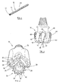
- tooth bits 16 have a body 26 upon which are mounted rolling cutters 28 with cutting teeth 30.
- weight is applied to the bit, forcing the cutting teeth 30 of the cutters 28 into the earth 29, and, as the bit 24 is rotated, the earth 29 causes the cutters 28 to rotate effecting a drilling action.
- the teeth 30 are generally wedge shaped with a pair of relatively flat flanks 32 and a crest 34. During drilling, the crest 34 is forced into the earth formation. By design, the rolling cutters do not allow a true rolling action of the teeth 30 when drilling. Therefore, each tooth 30 is scraped, or plowed a short distance through the earth formation as it is penetrating the earth. In order to prolong the life of the drill bit a hardfacing 36 is applied to the flanks 32 and crest 34 of the teeth 30 with the high density hard facing rod 10 of the present invention.
- FIG. 3 Another type of drill bit 16, a fixed cutter drag-type drill bit 38, is shown in Figure 3.
- the fixed cutter drill bit 38 comprises a bit body 40 machined from steel and having blades 42 formed on the leading face 43 of the bit 38. Extending side-by-side along each of the blades 42 is a plurality of cutting structures, indicated at 44.
- the gauge region 46 of the drill bit 38 must resist the loading and abrasion arising from constant scraping against the borehole wall 39. Therefore, there is applied to the surface 46 a hardfacing 48 with the high density hard facing rod 10 made by the process of the present invention.
- FIGs 5 and 6 there are shown other down hole tools utilizing the hardfacing applied from the high density hard facing rod of the present invention.
- a stabilizer 22 is shown with a plurality of blades 50.
- Each blade 50 must be able to withstand the severe abrasion and loads it is subjected to during operation.
- a hardfacing material 52 is often applied.
- Hardfacing 52 applied by the high density hard facing rod made by the process of the present invention is suitable for this application.
- the bias pad 18 repeatedly engages the sidewall 39 of the borehole 31 in order to push the tool to one side as directed by its control system. Because these bias pads 18 repeatedly apply extreme loads to the borehole wall 39, they must be coated with, or made from a very abrasion resistant and strong material such as a hardfacing 54 and applied by the high density hardfacing rod 10 made by a process of the present invention.
- FIGs 8 and 9 are shown other applications utilizing downhole tools 56, 58 having a hardfacing applied with a high density hard facing rod made process of the present invention.
- a number of different tools 56, 58 are shown in the drill string 60.
- These tools 56, 58 may include, but are not limited to, downhole motors, measuring while drilling tools, logging tools, vibration dampers, shock absorbers, and centralizers.
- These tools 56, 58 benefit from hardfacing applied with high density hard facing rod made by the process of the present invention.
- down hole bottom hole assemblies 62 as shown in Figure 7, are often operated while gravity is pushing them against the borehole wall 39. Once again the extreme abrasion and loads applied to the size of these tools make them benefit from a high pace in applied with a high density hardfacing rod made by the process of the present invention.
Landscapes
- Engineering & Computer Science (AREA)
- Chemical & Material Sciences (AREA)
- Mechanical Engineering (AREA)
- Materials Engineering (AREA)
- Metallurgy (AREA)
- Chemical Kinetics & Catalysis (AREA)
- Manufacturing & Machinery (AREA)
- Organic Chemistry (AREA)
- Physics & Mathematics (AREA)
- Plasma & Fusion (AREA)
- Composite Materials (AREA)
- Earth Drilling (AREA)
- Powder Metallurgy (AREA)
- Carbon And Carbon Compounds (AREA)
Applications Claiming Priority (2)
| Application Number | Priority Date | Filing Date | Title |
|---|---|---|---|
| US782341 | 1985-10-01 | ||
| US09/782,341 US6361739B1 (en) | 2001-02-13 | 2001-02-13 | Fabrication process for high density powder composite hardfacing rod |
Publications (3)
| Publication Number | Publication Date |
|---|---|
| EP1231014A2 true EP1231014A2 (de) | 2002-08-14 |
| EP1231014A3 EP1231014A3 (de) | 2004-02-04 |
| EP1231014B1 EP1231014B1 (de) | 2007-08-22 |
Family
ID=25125742
Family Applications (1)
| Application Number | Title | Priority Date | Filing Date |
|---|---|---|---|
| EP01305199A Expired - Lifetime EP1231014B1 (de) | 2001-02-13 | 2001-06-14 | Verfahren zum Herstellen von Aufschweissstaben aus Pulververbundwerkstoff mit erhöhter Dichte |
Country Status (4)
| Country | Link |
|---|---|
| US (1) | US6361739B1 (de) |
| EP (1) | EP1231014B1 (de) |
| AT (1) | ATE370814T1 (de) |
| DE (1) | DE60130094T2 (de) |
Cited By (1)
| Publication number | Priority date | Publication date | Assignee | Title |
|---|---|---|---|---|
| US9970235B2 (en) | 2012-10-15 | 2018-05-15 | Bertrand Lacour | Rotary steerable drilling system for drilling a borehole in an earth formation |
Families Citing this family (6)
| Publication number | Priority date | Publication date | Assignee | Title |
|---|---|---|---|---|
| US7666244B2 (en) * | 2004-07-08 | 2010-02-23 | Smith International, Inc. | Hardfacing milled-tooth drill bits using super dense carbide pellets |
| US20060024190A1 (en) | 2004-07-27 | 2006-02-02 | General Electric Company | Preparation of filler-metal weld rod by injection molding of powder |
| GB2459217B (en) * | 2007-01-08 | 2011-04-27 | Halliburton Energy Serv Inc | Drill bits and other downhole tools with hardfacing having tungsten carbide pellets and other hard materials |
| US9138832B2 (en) * | 2010-06-25 | 2015-09-22 | Halliburton Energy Services, Inc. | Erosion resistant hard composite materials |
| US9707643B2 (en) * | 2012-04-17 | 2017-07-18 | Hobart Brothers Company | Systems and methods for welding electrodes |
| US11000921B2 (en) | 2019-04-26 | 2021-05-11 | Kennametal Inc. | Composite welding rods and associated cladded articles |
Family Cites Families (16)
| Publication number | Priority date | Publication date | Assignee | Title |
|---|---|---|---|---|
| US1757601A (en) | 1928-01-30 | 1930-05-06 | Stoody Co | Welding rod |
| US3023130A (en) | 1959-08-06 | 1962-02-27 | Eutectic Welding Alloys | Hard surfacing material |
| US3179787A (en) * | 1962-03-29 | 1965-04-20 | Eutectic Welding Alloys | Carbide welding rod |
| US3847559A (en) * | 1969-05-28 | 1974-11-12 | Dewiant Corp | Erosion resistant composites |
| SE400202B (sv) * | 1974-08-30 | 1978-03-20 | Sandvik Ab | Sett att framstella en svetselektrod |
| SE452124B (sv) * | 1984-06-19 | 1987-11-16 | Kloster Speedsteel Ab | Emne till verktygsmatris av kompoundstal och sett att framstella dylikt |
| FR2590192B1 (fr) | 1985-11-21 | 1991-08-02 | Maybon Guy | Baguette souple de soudage a ame metallique enrobee, procede et dispositif pour sa realisation |
| US4741974A (en) | 1986-05-20 | 1988-05-03 | The Perkin-Elmer Corporation | Composite wire for wear resistant coatings |
| US4725508A (en) * | 1986-10-23 | 1988-02-16 | The Perkin-Elmer Corporation | Composite hard chromium compounds for thermal spraying |
| US4944774A (en) | 1987-12-29 | 1990-07-31 | Smith International, Inc. | Hard facing for milled tooth rock bits |
| US4836307A (en) | 1987-12-29 | 1989-06-06 | Smith International, Inc. | Hard facing for milled tooth rock bits |
| US5051112A (en) | 1988-06-29 | 1991-09-24 | Smith International, Inc. | Hard facing |
| US5667903A (en) * | 1995-05-10 | 1997-09-16 | Dresser Industries, Inc. | Method of hard facing a substrate, and weld rod used in hard facing a substrate |
| EP0753375B1 (de) * | 1995-07-03 | 2001-01-10 | Camco International Inc. | Hartauftragwerkstoff für Rollenbohrmeissel |
| US5740872A (en) | 1996-07-01 | 1998-04-21 | Camco International Inc. | Hardfacing material for rolling cutter drill bits |
| US6138779A (en) * | 1998-01-16 | 2000-10-31 | Dresser Industries, Inc. | Hardfacing having coated ceramic particles or coated particles of other hard materials placed on a rotary cone cutter |
-
2001
- 2001-02-13 US US09/782,341 patent/US6361739B1/en not_active Expired - Lifetime
- 2001-06-14 DE DE60130094T patent/DE60130094T2/de not_active Expired - Lifetime
- 2001-06-14 AT AT01305199T patent/ATE370814T1/de not_active IP Right Cessation
- 2001-06-14 EP EP01305199A patent/EP1231014B1/de not_active Expired - Lifetime
Cited By (1)
| Publication number | Priority date | Publication date | Assignee | Title |
|---|---|---|---|---|
| US9970235B2 (en) | 2012-10-15 | 2018-05-15 | Bertrand Lacour | Rotary steerable drilling system for drilling a borehole in an earth formation |
Also Published As
| Publication number | Publication date |
|---|---|
| DE60130094T2 (de) | 2008-05-15 |
| EP1231014B1 (de) | 2007-08-22 |
| DE60130094D1 (de) | 2007-10-04 |
| EP1231014A3 (de) | 2004-02-04 |
| US6361739B1 (en) | 2002-03-26 |
| ATE370814T1 (de) | 2007-09-15 |
Similar Documents
| Publication | Publication Date | Title |
|---|---|---|
| CA2384401C (en) | Roller cone bits with wear and fracture resistant surface | |
| US8459380B2 (en) | Earth-boring bits and other parts including cemented carbide | |
| US8002052B2 (en) | Particle-matrix composite drill bits with hardfacing | |
| CA2247599C (en) | Rock bit hardmetal overlay and process of manufacture | |
| US6469278B1 (en) | Hardfacing having coated ceramic particles or coated particles of other hard materials | |
| US8261632B2 (en) | Methods of forming earth-boring drill bits | |
| EP1957223B1 (de) | Erdbohrdrehbohrmeissel und verfahren zur herstellung von erdbohrdrehbohrmeisseln mit teilchenmatrixverbundstoffbohrmeisselkörpern | |
| US9987675B2 (en) | Manufacture of well tools with matrix materials | |
| US20100104874A1 (en) | High pressure sintering with carbon additives | |
| US5740872A (en) | Hardfacing material for rolling cutter drill bits | |
| RU2167262C2 (ru) | Наплавка твердым сплавом с покрытыми алмазными частицами (варианты), присадочный пруток для наплавки твердым сплавом, способ наплавки твердым сплавом (варианты), коническое шарошечное долото для вращательного бурения (варианты), коническая шарошка | |
| CN100567696C (zh) | 胎体钻头及制造方法 | |
| US6361739B1 (en) | Fabrication process for high density powder composite hardfacing rod | |
| EP1310322B1 (de) | Verfahren zum Herstellen von Stäben aus Pulververbundwerkstoff | |
| EP0753375B1 (de) | Hartauftragwerkstoff für Rollenbohrmeissel |
Legal Events
| Date | Code | Title | Description |
|---|---|---|---|
| PUAI | Public reference made under article 153(3) epc to a published international application that has entered the european phase |
Free format text: ORIGINAL CODE: 0009012 |
|
| AK | Designated contracting states |
Kind code of ref document: A2 Designated state(s): AT BE CH CY DE DK ES FI FR GB GR IE IT LI LU MC NL PT SE TR |
|
| AX | Request for extension of the european patent |
Free format text: AL;LT;LV;MK;RO;SI |
|
| RAP1 | Party data changed (applicant data changed or rights of an application transferred) |
Owner name: CAMCO INTERNATIONAL (UK) LTD. |
|
| PUAL | Search report despatched |
Free format text: ORIGINAL CODE: 0009013 |
|
| AK | Designated contracting states |
Kind code of ref document: A3 Designated state(s): AT BE CH CY DE DK ES FI FR GB GR IE IT LI LU MC NL PT SE TR |
|
| AX | Request for extension of the european patent |
Extension state: AL LT LV MK RO SI |
|
| RIC1 | Information provided on ipc code assigned before grant |
Ipc: 7B 23K 35/02 A Ipc: 7B 23K 35/32 B Ipc: 7B 23K 35/40 B |
|
| 17P | Request for examination filed |
Effective date: 20040330 |
|
| AKX | Designation fees paid |
Designated state(s): AT BE CH CY DE DK ES FI FR GB GR IE IT LI LU MC NL PT SE TR |
|
| GRAP | Despatch of communication of intention to grant a patent |
Free format text: ORIGINAL CODE: EPIDOSNIGR1 |
|
| GRAS | Grant fee paid |
Free format text: ORIGINAL CODE: EPIDOSNIGR3 |
|
| GRAA | (expected) grant |
Free format text: ORIGINAL CODE: 0009210 |
|
| AK | Designated contracting states |
Kind code of ref document: B1 Designated state(s): AT BE CH CY DE DK ES FI FR GB GR IE IT LI LU MC NL PT SE TR |
|
| REG | Reference to a national code |
Ref country code: GB Ref legal event code: FG4D |
|
| REG | Reference to a national code |
Ref country code: CH Ref legal event code: EP |
|
| REG | Reference to a national code |
Ref country code: IE Ref legal event code: FG4D |
|
| REF | Corresponds to: |
Ref document number: 60130094 Country of ref document: DE Date of ref document: 20071004 Kind code of ref document: P |
|
| PG25 | Lapsed in a contracting state [announced via postgrant information from national office to epo] |
Ref country code: FI Free format text: LAPSE BECAUSE OF FAILURE TO SUBMIT A TRANSLATION OF THE DESCRIPTION OR TO PAY THE FEE WITHIN THE PRESCRIBED TIME-LIMIT Effective date: 20070822 Ref country code: NL Free format text: LAPSE BECAUSE OF FAILURE TO SUBMIT A TRANSLATION OF THE DESCRIPTION OR TO PAY THE FEE WITHIN THE PRESCRIBED TIME-LIMIT Effective date: 20070822 Ref country code: ES Free format text: LAPSE BECAUSE OF FAILURE TO SUBMIT A TRANSLATION OF THE DESCRIPTION OR TO PAY THE FEE WITHIN THE PRESCRIBED TIME-LIMIT Effective date: 20071203 |
|
| NLV1 | Nl: lapsed or annulled due to failure to fulfill the requirements of art. 29p and 29m of the patents act | ||
| PG25 | Lapsed in a contracting state [announced via postgrant information from national office to epo] |
Ref country code: CH Free format text: LAPSE BECAUSE OF FAILURE TO SUBMIT A TRANSLATION OF THE DESCRIPTION OR TO PAY THE FEE WITHIN THE PRESCRIBED TIME-LIMIT Effective date: 20070822 Ref country code: AT Free format text: LAPSE BECAUSE OF FAILURE TO SUBMIT A TRANSLATION OF THE DESCRIPTION OR TO PAY THE FEE WITHIN THE PRESCRIBED TIME-LIMIT Effective date: 20070822 Ref country code: LI Free format text: LAPSE BECAUSE OF FAILURE TO SUBMIT A TRANSLATION OF THE DESCRIPTION OR TO PAY THE FEE WITHIN THE PRESCRIBED TIME-LIMIT Effective date: 20070822 |
|
| REG | Reference to a national code |
Ref country code: CH Ref legal event code: PL |
|
| ET | Fr: translation filed | ||
| PG25 | Lapsed in a contracting state [announced via postgrant information from national office to epo] |
Ref country code: GR Free format text: LAPSE BECAUSE OF FAILURE TO SUBMIT A TRANSLATION OF THE DESCRIPTION OR TO PAY THE FEE WITHIN THE PRESCRIBED TIME-LIMIT Effective date: 20071123 Ref country code: DK Free format text: LAPSE BECAUSE OF FAILURE TO SUBMIT A TRANSLATION OF THE DESCRIPTION OR TO PAY THE FEE WITHIN THE PRESCRIBED TIME-LIMIT Effective date: 20070822 |
|
| PG25 | Lapsed in a contracting state [announced via postgrant information from national office to epo] |
Ref country code: PT Free format text: LAPSE BECAUSE OF FAILURE TO SUBMIT A TRANSLATION OF THE DESCRIPTION OR TO PAY THE FEE WITHIN THE PRESCRIBED TIME-LIMIT Effective date: 20080122 |
|
| PLBE | No opposition filed within time limit |
Free format text: ORIGINAL CODE: 0009261 |
|
| STAA | Information on the status of an ep patent application or granted ep patent |
Free format text: STATUS: NO OPPOSITION FILED WITHIN TIME LIMIT |
|
| PG25 | Lapsed in a contracting state [announced via postgrant information from national office to epo] |
Ref country code: SE Free format text: LAPSE BECAUSE OF FAILURE TO SUBMIT A TRANSLATION OF THE DESCRIPTION OR TO PAY THE FEE WITHIN THE PRESCRIBED TIME-LIMIT Effective date: 20071122 |
|
| 26N | No opposition filed |
Effective date: 20080526 |
|
| PG25 | Lapsed in a contracting state [announced via postgrant information from national office to epo] |
Ref country code: MC Free format text: LAPSE BECAUSE OF NON-PAYMENT OF DUE FEES Effective date: 20080630 |
|
| PG25 | Lapsed in a contracting state [announced via postgrant information from national office to epo] |
Ref country code: IE Free format text: LAPSE BECAUSE OF NON-PAYMENT OF DUE FEES Effective date: 20080616 |
|
| PG25 | Lapsed in a contracting state [announced via postgrant information from national office to epo] |
Ref country code: CY Free format text: LAPSE BECAUSE OF FAILURE TO SUBMIT A TRANSLATION OF THE DESCRIPTION OR TO PAY THE FEE WITHIN THE PRESCRIBED TIME-LIMIT Effective date: 20070822 |
|
| PG25 | Lapsed in a contracting state [announced via postgrant information from national office to epo] |
Ref country code: LU Free format text: LAPSE BECAUSE OF NON-PAYMENT OF DUE FEES Effective date: 20080614 |
|
| PG25 | Lapsed in a contracting state [announced via postgrant information from national office to epo] |
Ref country code: TR Free format text: LAPSE BECAUSE OF FAILURE TO SUBMIT A TRANSLATION OF THE DESCRIPTION OR TO PAY THE FEE WITHIN THE PRESCRIBED TIME-LIMIT Effective date: 20070822 |
|
| REG | Reference to a national code |
Ref country code: FR Ref legal event code: PLFP Year of fee payment: 16 |
|
| REG | Reference to a national code |
Ref country code: FR Ref legal event code: PLFP Year of fee payment: 17 |
|
| REG | Reference to a national code |
Ref country code: FR Ref legal event code: PLFP Year of fee payment: 18 |
|
| PGFP | Annual fee paid to national office [announced via postgrant information from national office to epo] |
Ref country code: BE Payment date: 20190417 Year of fee payment: 19 |
|
| PGFP | Annual fee paid to national office [announced via postgrant information from national office to epo] |
Ref country code: FR Payment date: 20200512 Year of fee payment: 20 Ref country code: DE Payment date: 20200602 Year of fee payment: 20 |
|
| PGFP | Annual fee paid to national office [announced via postgrant information from national office to epo] |
Ref country code: GB Payment date: 20200603 Year of fee payment: 20 Ref country code: IT Payment date: 20200512 Year of fee payment: 20 |
|
| REG | Reference to a national code |
Ref country code: BE Ref legal event code: MM Effective date: 20200630 |
|
| PG25 | Lapsed in a contracting state [announced via postgrant information from national office to epo] |
Ref country code: BE Free format text: LAPSE BECAUSE OF NON-PAYMENT OF DUE FEES Effective date: 20200630 |
|
| REG | Reference to a national code |
Ref country code: DE Ref legal event code: R071 Ref document number: 60130094 Country of ref document: DE |
|
| REG | Reference to a national code |
Ref country code: GB Ref legal event code: PE20 Expiry date: 20210613 |
|
| PG25 | Lapsed in a contracting state [announced via postgrant information from national office to epo] |
Ref country code: GB Free format text: LAPSE BECAUSE OF EXPIRATION OF PROTECTION Effective date: 20210613 |