EP1231081A2 - Bandage pneumatique pour véhicules - Google Patents
Bandage pneumatique pour véhicules Download PDFInfo
- Publication number
- EP1231081A2 EP1231081A2 EP02002616A EP02002616A EP1231081A2 EP 1231081 A2 EP1231081 A2 EP 1231081A2 EP 02002616 A EP02002616 A EP 02002616A EP 02002616 A EP02002616 A EP 02002616A EP 1231081 A2 EP1231081 A2 EP 1231081A2
- Authority
- EP
- European Patent Office
- Prior art keywords
- vehicle tire
- tire according
- knobs
- elevations
- tip
- Prior art date
- Legal status (The legal status is an assumption and is not a legal conclusion. Google has not performed a legal analysis and makes no representation as to the accuracy of the status listed.)
- Withdrawn
Links
Images

Classifications
-
- B—PERFORMING OPERATIONS; TRANSPORTING
- B60—VEHICLES IN GENERAL
- B60C—VEHICLE TYRES; TYRE INFLATION; TYRE CHANGING; CONNECTING VALVES TO INFLATABLE ELASTIC BODIES IN GENERAL; DEVICES OR ARRANGEMENTS RELATED TO TYRES
- B60C11/00—Tyre tread bands; Tread patterns; Anti-skid inserts
- B60C11/03—Tread patterns
- B60C11/13—Tread patterns characterised by the groove cross-section, e.g. for buttressing or preventing stone-trapping
-
- B—PERFORMING OPERATIONS; TRANSPORTING
- B08—CLEANING
- B08B—CLEANING IN GENERAL; PREVENTION OF FOULING IN GENERAL
- B08B17/00—Methods preventing fouling
- B08B17/02—Preventing deposition of fouling or of dust
- B08B17/06—Preventing deposition of fouling or of dust by giving articles subject to fouling a special shape or arrangement
- B08B17/065—Preventing deposition of fouling or of dust by giving articles subject to fouling a special shape or arrangement the surface having a microscopic surface pattern to achieve the same effect as a lotus flower
-
- B—PERFORMING OPERATIONS; TRANSPORTING
- B60—VEHICLES IN GENERAL
- B60C—VEHICLE TYRES; TYRE INFLATION; TYRE CHANGING; CONNECTING VALVES TO INFLATABLE ELASTIC BODIES IN GENERAL; DEVICES OR ARRANGEMENTS RELATED TO TYRES
- B60C11/00—Tyre tread bands; Tread patterns; Anti-skid inserts
- B60C11/03—Tread patterns
- B60C11/032—Patterns comprising isolated recesses
-
- B—PERFORMING OPERATIONS; TRANSPORTING
- B29—WORKING OF PLASTICS; WORKING OF SUBSTANCES IN A PLASTIC STATE IN GENERAL
- B29C—SHAPING OR JOINING OF PLASTICS; SHAPING OF MATERIAL IN A PLASTIC STATE, NOT OTHERWISE PROVIDED FOR; AFTER-TREATMENT OF THE SHAPED PRODUCTS, e.g. REPAIRING
- B29C45/00—Injection moulding, i.e. forcing the required volume of moulding material through a nozzle into a closed mould; Apparatus therefor
- B29C45/17—Component parts, details or accessories; Auxiliary operations
- B29C45/26—Moulds
- B29C45/37—Mould cavity walls, i.e. the inner surface forming the mould cavity, e.g. linings
- B29C45/372—Mould cavity walls, i.e. the inner surface forming the mould cavity, e.g. linings provided with means for marking or patterning, e.g. numbering articles
Definitions
- the invention relates to a vehicle tire with a tread, which by a Number of grooves, such as circumferential grooves and / or transverse grooves, is divided into a number of positive profiles, such as profile blocks and / or strips, and with externally visible surface areas with a microscopic Shape from a variety of surveys, especially in the form of pointed Corrugations and / or knobs.
- the invention is concerned with another advantageous application to find such a surface structure on the vehicle tire.
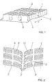
- Fig. 1 shows a view of a portion of a tread pattern with a Number of profile blocks 1.
- the profile blocks 1 are arranged in rows of blocks that run parallel to the circumferential direction, which in Fig. 1 by the double arrow F is marked.
- the individual profile blocks 1 are by circumferential grooves 2 and separated from each other by transverse grooves 3. Enough for the section shown both the circumferential grooves 2 and the transverse grooves 3 to the intended Tread depth, which is generally 7 to 8 mm for car tires.
- the individual profile blocks 1 are also each with a number of incisions 4 provided that the profile blocks 1 parallel to the Cross transverse grooves 3.
- the incisions 4 have a zigzag course on and can be made in the usual width for cuts from 0.4 to 0.6 mm his.
- Fig. 2 shows a possible variant of a tread pattern for a car winter tire on the basis of a partial processing
- the one shown here Tread pattern a wide central circumferential groove 2 'and one on each shoulder has another wide circumferential groove 2 '.
- V-shaped and thus arrow-shaped transverse grooves 3 ' is the profile in profile blocks 1' divided.
- Narrower circumferential grooves 12, each between the central Circumferential groove 2 'and the wide shoulder-side circumferential grooves 2' run, effect a further structuring of the profile in rows of blocks.
- the area of the groove base of the circumferential grooves 2, 2 'and 12 and the transverse grooves 3, 3 ' at least in part with a special one microscopic surface design.
- Under the groove bottom understood at least that area of the surfaces delimiting the grooves that the here forms a curved "valley area" between adjacent blocks. In Fig. 1 lies this area below the dashed line.
- the following microscopic shape of the rubber surfaces in the area of the However, the bottom of the groove can also extend to the periphery of the profile blocks 1, 1 ' extend.
- Fig. 3 shows an embodiment of this microscopic shape using a greatly enlarged cross section through the detail denoted by A from Fig. 1 and 2.
- the microscopic shape is made up of tiny knobs 5 of a certain size and arrangement together.
- the knobs 5 are at least essentially dome-shaped, all at least essentially the same size and arranged regularly.
- the knobs 5 have a height h which is about at least 10 ⁇ m the surrounding valleys of the microscopic Surface shape protrudes, where h between 10 and 25 microns, in particular between 15 to 20 ⁇ m is selected.
- the largest diameter d of the knobs 5 corresponds essentially to their height h or is slightly larger or smaller than this.
- the mutual distance a at the base of adjacent knobs 5 is 5 between 5 and 25 ⁇ m, especially between 15 and 20 ⁇ m.
- the distance b from Nub tip to nub tip is between 5 and 60 ⁇ m and is special ⁇ 20 ⁇ m, preferably between 15 and 20 ⁇ m.
- knobs 5 In the embodiment shown in Fig. 4, the knobs 5 'have different Sizes on and are also arranged more irregularly. This one too However, the above-mentioned areas apply to the variant in the embodiment shown dimensions a, h, d and b.
- the tips or tip areas are also the Nubs 5, 5 'with a radius of curvature of the order of magnitude between 3 ⁇ m and 25 ⁇ m.
- the effects of self-cleaning and the very low adhesion of water can also be achieved by corrugating the surface. Under corrugation is there a number of at least essentially parallel to each other
- elevations 6 as shown for example in Fig. 5.
- the individual elevations 6 have a dome-shaped and thus the cross section 3 very similar cross-section.
- the elevations 6 can as shown, have a straight course or in any shape run curved.
- the distance b 'becomes adjacent Burr regions 6a between 4 ⁇ m and 40 ⁇ m, in particular ⁇ 15 ⁇ m.
- the mutual distance a 'in the area of the base from the adjacent elevations 6 is between 5 and 10 ⁇ m.
- the height h 'of the elevations 6 extends beyond at least 10 ⁇ m the surrounding valleys of the surface shape, where h ' up to 25 ⁇ m, but in particular between 15 and 20 ⁇ m.
- the ripple ridges 6a also have a surface radius of curvature, here in the Order of magnitude between 2 and 15 ⁇ m. Also in this embodiment, that the elevations 6 forming a certain surface area also different cross-sectional sizes can be provided.
- the cross-sectional shape of a dome is in the illustrated embodiments the preferred cross-sectional shape.
- the initially conventionally manufactured webs with the usual smooth metal surface can be created. You can then use a Laser beam introduced grid-shaped or dot-grid-shaped depressions between which corresponding raised areas remain.
- Surfaces according to the invention can also have a different shape, for example similar to a shark skin.
Landscapes
- Engineering & Computer Science (AREA)
- Mechanical Engineering (AREA)
- Tires In General (AREA)
Applications Claiming Priority (2)
| Application Number | Priority Date | Filing Date | Title |
|---|---|---|---|
| DE10106454A DE10106454A1 (de) | 2001-02-09 | 2001-02-09 | Fahrzeugreifen |
| DE10106454 | 2001-02-09 |
Publications (2)
| Publication Number | Publication Date |
|---|---|
| EP1231081A2 true EP1231081A2 (fr) | 2002-08-14 |
| EP1231081A3 EP1231081A3 (fr) | 2003-05-14 |
Family
ID=7673752
Family Applications (1)
| Application Number | Title | Priority Date | Filing Date |
|---|---|---|---|
| EP02002616A Withdrawn EP1231081A3 (fr) | 2001-02-09 | 2002-02-05 | Bandage pneumatique pour véhicules |
Country Status (2)
| Country | Link |
|---|---|
| EP (1) | EP1231081A3 (fr) |
| DE (1) | DE10106454A1 (fr) |
Cited By (2)
| Publication number | Priority date | Publication date | Assignee | Title |
|---|---|---|---|---|
| US20140352862A1 (en) * | 2011-12-28 | 2014-12-04 | Bridgestone Corporation | Tire and tire forming mold |
| CN113825652A (zh) * | 2019-05-27 | 2021-12-21 | 横滨橡胶株式会社 | 充气轮胎 |
Families Citing this family (1)
| Publication number | Priority date | Publication date | Assignee | Title |
|---|---|---|---|---|
| DE102004014007A1 (de) * | 2004-03-23 | 2005-10-13 | Continental Ag | Lamelle zur Verwendung in einer Reifenvulkanisationsform und Verfahren zu deren Herstellung |
Family Cites Families (4)
| Publication number | Priority date | Publication date | Assignee | Title |
|---|---|---|---|---|
| JP3249673B2 (ja) * | 1994-01-21 | 2002-01-21 | 株式会社ブリヂストン | 空気入りタイヤ及び空気入りタイヤの製造方法 |
| US6189586B1 (en) * | 1998-10-15 | 2001-02-20 | Warren L. Guidry | Pneumatic rubber tire for on/off-road vehicles |
| DE19928863A1 (de) * | 1999-06-24 | 2001-01-04 | Continental Ag | Fahrzeugreifen |
| BR0016045A (pt) * | 1999-11-30 | 2002-07-23 | Pirelli | Pneu para rodas de veìculos, particularmente para rodas direcionadoras de veìculos a motor para transporte pesado |
-
2001
- 2001-02-09 DE DE10106454A patent/DE10106454A1/de not_active Withdrawn
-
2002
- 2002-02-05 EP EP02002616A patent/EP1231081A3/fr not_active Withdrawn
Cited By (2)
| Publication number | Priority date | Publication date | Assignee | Title |
|---|---|---|---|---|
| US20140352862A1 (en) * | 2011-12-28 | 2014-12-04 | Bridgestone Corporation | Tire and tire forming mold |
| CN113825652A (zh) * | 2019-05-27 | 2021-12-21 | 横滨橡胶株式会社 | 充气轮胎 |
Also Published As
| Publication number | Publication date |
|---|---|
| EP1231081A3 (fr) | 2003-05-14 |
| DE10106454A1 (de) | 2002-08-14 |
Similar Documents
| Publication | Publication Date | Title |
|---|---|---|
| EP1063071A2 (fr) | Article en polymère avec une surface structurée, en particulier pneumatique, moule et fabrication du moule | |
| EP2193038B1 (fr) | Pneumatique pour véhicule | |
| WO2008122455A1 (fr) | Pneumatique de véhicule à moteur | |
| DE102009044242A1 (de) | Laufstreifenprofil eines Fahrzeugluftreifens | |
| AT404244B (de) | Fahrzeugreifen mit einem laufstreifen | |
| DE1680404C3 (de) | Luftreifen | |
| EP3415343B1 (fr) | Profilé de bande de roulement d'un pneu de véhicule pour l'utilisation sur une voie en hiver | |
| DE10101507A1 (de) | Fahrzeugreifen | |
| DE19650655C2 (de) | Fahrzeugreifen mit Einschnitten im Laufstreifen | |
| DE102008024075A1 (de) | Fahrzeugluftreifen | |
| EP1872974B1 (fr) | Pneu doté d'une bande de roulement profilée | |
| EP0864448B1 (fr) | Bandage pneumatique pour véhicule pourvu d'incisions dans le profil, lamelle pour le moule de vulcanisation et moule de vulcanisation avec de telles lamelles | |
| EP2570273B1 (fr) | Bande de roulement de pneu de véhicule | |
| WO2019105624A1 (fr) | Pneumatique de véhicule | |
| DE10049936B4 (de) | Fahrzeugreifen | |
| EP1231081A2 (fr) | Bandage pneumatique pour véhicules | |
| DE102018204245A1 (de) | Fahrzeugluftreifen | |
| DE19957914A1 (de) | Fahrzeugluftreifen | |
| DE102008029660A1 (de) | Fahrzeugluftreifen | |
| DE102021212509A1 (de) | Fahrzeugreifen | |
| DE102022210967A1 (de) | Fahrzeugreifen, Verfahren zur Herstellung eines Fahrzeugreifens und Vulkanisationsform | |
| DE102009059185A1 (de) | Fahrzeugluftreifen | |
| DE69608216T2 (de) | Luftreifen | |
| EP4389460B1 (fr) | Bandage pneumatique pour véhicule | |
| CH651254A5 (en) | Pneumatic vehicle tyres with a tread profile consisting of profile blocks |
Legal Events
| Date | Code | Title | Description |
|---|---|---|---|
| PUAI | Public reference made under article 153(3) epc to a published international application that has entered the european phase |
Free format text: ORIGINAL CODE: 0009012 |
|
| AK | Designated contracting states |
Kind code of ref document: A2 Designated state(s): AT BE CH CY DE DK ES FI FR GB GR IE IT LI LU MC NL PT SE TR |
|
| AX | Request for extension of the european patent |
Free format text: AL;LT;LV;MK;RO;SI |
|
| PUAL | Search report despatched |
Free format text: ORIGINAL CODE: 0009013 |
|
| AK | Designated contracting states |
Designated state(s): AT BE CH CY DE DK ES FI FR GB GR IE IT LI LU MC NL PT SE TR |
|
| AX | Request for extension of the european patent |
Extension state: AL LT LV MK RO SI |
|
| STAA | Information on the status of an ep patent application or granted ep patent |
Free format text: STATUS: THE APPLICATION HAS BEEN WITHDRAWN |
|
| 18W | Application withdrawn |
Effective date: 20030516 |