EP1231095A2 - Auf Bedarf zuschaltbares Differential - Google Patents
Auf Bedarf zuschaltbares Differential Download PDFInfo
- Publication number
- EP1231095A2 EP1231095A2 EP02075583A EP02075583A EP1231095A2 EP 1231095 A2 EP1231095 A2 EP 1231095A2 EP 02075583 A EP02075583 A EP 02075583A EP 02075583 A EP02075583 A EP 02075583A EP 1231095 A2 EP1231095 A2 EP 1231095A2
- Authority
- EP
- European Patent Office
- Prior art keywords
- differential
- assembly
- cam member
- structures
- engaged
- Prior art date
- Legal status (The legal status is an assumption and is not a legal conclusion. Google has not performed a legal analysis and makes no representation as to the accuracy of the status listed.)
- Ceased
Links
Images


Classifications
-
- B—PERFORMING OPERATIONS; TRANSPORTING
- B60—VEHICLES IN GENERAL
- B60K—ARRANGEMENT OR MOUNTING OF PROPULSION UNITS OR OF TRANSMISSIONS IN VEHICLES; ARRANGEMENT OR MOUNTING OF PLURAL DIVERSE PRIME-MOVERS IN VEHICLES; AUXILIARY DRIVES FOR VEHICLES; INSTRUMENTATION OR DASHBOARDS FOR VEHICLES; ARRANGEMENTS IN CONNECTION WITH COOLING, AIR INTAKE, GAS EXHAUST OR FUEL SUPPLY OF PROPULSION UNITS IN VEHICLES
- B60K17/00—Arrangement or mounting of transmissions in vehicles
- B60K17/34—Arrangement or mounting of transmissions in vehicles for driving both front and rear wheels, e.g. four wheel drive vehicles
-
- B—PERFORMING OPERATIONS; TRANSPORTING
- B60—VEHICLES IN GENERAL
- B60K—ARRANGEMENT OR MOUNTING OF PROPULSION UNITS OR OF TRANSMISSIONS IN VEHICLES; ARRANGEMENT OR MOUNTING OF PLURAL DIVERSE PRIME-MOVERS IN VEHICLES; AUXILIARY DRIVES FOR VEHICLES; INSTRUMENTATION OR DASHBOARDS FOR VEHICLES; ARRANGEMENTS IN CONNECTION WITH COOLING, AIR INTAKE, GAS EXHAUST OR FUEL SUPPLY OF PROPULSION UNITS IN VEHICLES
- B60K23/00—Arrangement or mounting of control devices for vehicle transmissions, or parts thereof, not otherwise provided for
- B60K23/08—Arrangement or mounting of control devices for vehicle transmissions, or parts thereof, not otherwise provided for for changing number of driven wheels, for switching from driving one axle to driving two or more axles
-
- B—PERFORMING OPERATIONS; TRANSPORTING
- B60—VEHICLES IN GENERAL
- B60K—ARRANGEMENT OR MOUNTING OF PROPULSION UNITS OR OF TRANSMISSIONS IN VEHICLES; ARRANGEMENT OR MOUNTING OF PLURAL DIVERSE PRIME-MOVERS IN VEHICLES; AUXILIARY DRIVES FOR VEHICLES; INSTRUMENTATION OR DASHBOARDS FOR VEHICLES; ARRANGEMENTS IN CONNECTION WITH COOLING, AIR INTAKE, GAS EXHAUST OR FUEL SUPPLY OF PROPULSION UNITS IN VEHICLES
- B60K17/00—Arrangement or mounting of transmissions in vehicles
- B60K17/34—Arrangement or mounting of transmissions in vehicles for driving both front and rear wheels, e.g. four wheel drive vehicles
- B60K17/344—Arrangement or mounting of transmissions in vehicles for driving both front and rear wheels, e.g. four wheel drive vehicles having a transfer gear
Definitions
- the present invention generally relates to vehicle drivelines and more particularly to a differential assembly for a vehicle driveline that selectively transmits power to a set of vehicle wheels.
- vehicle manufacturers are employing vehicle drivetrains having more than one drive axle to improve vehicle traction.
- Common arrangements include part-time four-wheel drive systems that employ a front axle disconnect to selectively disconnect the front wheels from the front of the vehicle drivetrain. These arrangements are commonly known as rear drive/front assist drivetrains. Disconnection of the front wheels from the front of the vehicle drivetrain prevents the front drive wheels from rotating the front of the vehicle drive train at road speed, thereby saving wear and tear on the vehicle driveline.
- the front axle disconnect also controls the coupling of the front wheels to the front of the vehicle driveline such that the front driveshaft will spin at the same speed as the rear driveshaft.
- front axle disconnects typically use a sliding sleeve to connect or disconnect an axle shaft from the front differential side gear.
- Vehicle manufacturers typically use either vacuum or heat to move the engagement sleeve and as such, the time that is required to shift the sliding sleeve to a desired position can be relatively long, particularly when heat is employed to heat a fluid to generate sufficient pressure to cause the engagement sleeve to move.
- the present invention provides a differential assembly having first, second and third structures, a differential gear set and a biasing mechanism.
- the first structure is configured to rotate along a differential axis in response to receipt of a rotational input.
- the second structure is supported for rotation on the differential axis.
- the third structure is supported for rotation on the differential axis and disposed between the first and second structures.
- the third structure can be operated in an engaged condition for transmitting torque from the first structure to the second structure and a disengaged condition for inhibiting the transmission of torque from the first structure to the second structure.
- the differential gear set is coupled to and rotatably supported within the second structure.
- the biasing mechanism biases the third structure in the disengaged condition.
- the third structure is placed in the engaged condition if a torsional magnitude of the rotational input exceeds by a predetermined amount a torsional magnitude of a rotational force exerted through the differential gear set.
- the present invention provides a vehicle drive train having a transfer case assembly and first and second axle assemblies.
- the transfer case assembly receives a rotational input from a vehicle power source and produces first and second intermediate rotational outputs therefrom.
- the first axle assembly is coupled to the transfer case assembly, receives the first intermediate rotational output therefrom and produces a first drive wheel output for rotating a first set of drive wheels.
- the second axle assembly has a differential assembly with a differential housing member configured to rotate about differential axis in response to receipt of the second intermediate rotational output, a differential case member supported for rotation on the differential axis, a cam member supported for rotation on the differential axis and disposed between the differential housing member and the differential case member and a differential gear set.
- the cam member can be operated in an engaged condition for transmitting torque from the differential housing member to the differential case member and a disengaged condition for inhibiting the transmission of torque from the differential housing member to the differential case member.
- the differential gear set is coupled to and rotatably supported within the differential case member. Operation of the cam member in the engaged condition permits the differential gear set to produce a second drive wheel output to rotate a second set of drive wheels. Operation of the cam member in the disengaged condition inhibits the differential from producing the second drive wheel output and permitting the second set of drive wheels to rotate freely.
- a drivetrain 10 for a part-time four-wheel drive vehicle 12 is schematically shown interactively associated with a differential assembly 14 constructed in accordance with the teachings of the present invention.
- the drivetrain 10 includes a rear driveline 20 and a front driveline 22 which are both drivable from a source of power, such as an engine 24, through a transmission 26 which may be of either the manual or automatic type.
- the drivetrain 10 is a rear drive/front assist system which incorporates a transfer case 28 for transmitting drive torque from the engine 24 and the transmission 26 to the rear and front drivelines 20 and 22.
- the transfer case 28 is preferably a non-differentiating transfer case that causes the rear and front transfer case output shafts 30 and 32, respectively to rotate at the same rotational speed.
- the rear driveline 20 is conventional in its construction and operation and includes a pair of rear wheels 36 connected at the opposite ends of a rear axle assembly 38 having a rear differential assembly 40 coupled to one end of a rear prop shaft 42, the opposite end of which is interconnected to a rear transfer case output shaft 30 of the transfer case 28.
- the rear axle assembly 38 includes a rear axle housing 44, a rear pinion shaft 46 and a pair of rear axle shafts 48 that are interconnected to a respective one of the left and right rear wheels 36.
- the rear axle housing 44 has a wall member 50 that defines a differential cavity 52 into which the rear differential assembly 40 is rotatably supported.
- the rear pinion shaft 46 has a pinion gear 54 that is fixed thereto which drives a ring gear 56 that is fixed to a differential case 58 of the rear differential assembly 40.
- a gearset 60 supported within the differential case 58 transfers rotary power from the differential case 58 to the rear axle shafts 48 to facilitate relative rotation (i.e., differentiation) therebetween.
- rotary power from the engine 24 is transmitted to the rear axle shafts 48 for driving the left and right rear wheels 36 via the transmission 26, the transfer case 28, the rear prop shaft 42, the rear pinion shaft 46, the differential case 58 and the gearset 60.
- the front driveline 22 includes a pair of front wheels 66 connected at the opposite ends of a front axle assembly 68 having the differential assembly 14 coupled to one end of a front prop shaft 72, the opposite end of which is interconnected to the front transfer case output shaft 32 of the transfer case 28.
- the front axle assembly 68 includes a front axle housing 74, a front pinion shaft 76, the front differential assembly 14, a pair of front axle shafts 78, that are interconnected to left and right front wheels 66.
- the front axle housing 74 has a wall member 80 that defines a differential cavity 82 into which the front differential assembly 14 is supported for rotation about a differential axis 83.
- the front pinion shaft 76 has a pinion gear 84 that is fixed thereto which drives a ring gear 86 that is fixed to a differential housing assembly 88 of the front differential assembly 14.
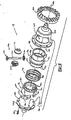
- the front differential assembly 14 is shown in greater detail to also include a cam member 90, a differential case member 92, a biasing mechanism 94, a gearset 96 and a thrust washer 98.
- the differential housing assembly 88 includes a first housing member 100 and a second housing member 102 that collectively define a differential cavity 104.
- the first housing member 100 is generally hollow and includes a retaining flange 106, an extending portion 108 and a first housing aperture 110.
- the retaining flange 106 is operable for receiving a plurality of fasteners 114 to permit the first and second housing members 100 and 102 and the ring gear 86 to be fixedly but removably coupled together.
- the extending portion 108 is configured to at least partially extend into a second housing aperture 118 formed into the second housing member 102.
- the extending portion 108 terminates at an abutting face 120 that is configured to abut an abutting face 122 formed in the cam member 90.
- Each of the abutting faces 120 and 122 are illustrated to be formed by a plurality of peaks 124 and valleys 126, the purpose of which will be discussed in greater detail, below.
- the cam member 90 is illustrated to have a generally hollow cylindrical configuration and is rotatably supported within the differential cavity 104 between the first housing member 100 and the differential case member 92.
- the cam member 90 includes a cam portion 130 into which the abutting face 122 is formed, a collar portion 132, a plurality of teeth 134 and an aperture 136 extending through the cam member 90 and formed along the longitudinal axis of the cam member 90.
- Bushings or bearings may be mounted within the second housing member 102 in the second housing aperture 118 to support the cam member 90 for rotation within the differential cavity 104 about the differential axis 83.
- Each of the plurality of teeth 134 formed into the cam member 90 are illustrated to have a generally square configuration that is configured to meshingly engage a plurality of teeth 140 formed in the differential case member 92 to permit rotary power to be transferred between the cam member 90 and the differential case member 92.
- the particular configuration of the teeth 134 and 140 which is illustrated is merely exemplary and not intended to be limiting in any manner. Accordingly, those skilled in the art will understand that the teeth 134 and 140 may have another configuration or that they may be omitted altogether if another means for transferring power between the cam member 90 and the differential case member 92, such as one that utilizes friction between the mating surfaces of the cam member 90 and the differential case member 92, is employed.
- the cam member 90 is operable in a disengaged condition and an engaged condition.
- the peaks 124 and valleys 126 of the abutting face 120 of the first housing member 100 are positioned against the valleys 126 and peaks 124, respectively, of the abutting face 122 of the cam member 90 and the teeth 134 formed in the cam member 90 are spaced apart from the teeth 140 formed into the differential case member 92.
- rotary power cannot be transmitted between the cam member 90 and the differential case member 92.
- the peaks 124 and valleys 126 of the abutting face 120 of the first housing member 100 are positioned against the peaks 124 and valleys 126, respectively, of the abutting face 122 of the cam member 90 and the teeth 134 formed in the cam member 90 are meshingly engaged with the teeth 140 formed into the differential case member 92, thereby facilitating the transmission of rotary power therebetween.
- the differential case member 92 is also illustrated to have a generally hollow cylindrical configuration.
- the differential case member 92 includes a flange member 146 and a pinion shaft aperture 148 which is positioned generally perpendicularly to the longitudinal axis of the differential case member 92.
- bushings or bearings may be mounted within the second housing member 102 in the second housing aperture 118 to support the differential case member 92 for rotation within the differential cavity 104 about the differential axis 83.
- the end of the differential case member 92 opposite the end having the teeth 140 terminates at a thrust flange 150 that is configured to contact the thrust washer 98.
- the thrust washer 98 is disposed between the thrust flange 150 and an end portion 154 of the second housing member 102 being configured to reduce the friction between the thrust flange 150 and the end portion 154.
- the gearset 96 is illustrated to include a pinion shaft 170, a pair of pinions 172 and a pair of side gears 174.
- the pinion shaft 170 extends through the pinion shaft aperture 148 and is fixedly coupled to the differential case member 92.
- the pinion shaft 170 rotatably supports the pair of pinions 172, each of which is meshingly engaged to the pair of side gears 174.
- the front axle shafts 78 are coupled at a first end to an associated one of the side gears 174 and at an opposite end to an associated one of the left and right front wheels 66.
- the biasing mechanism 94 is operable for maintaining the cam member 90 in the disengaged condition until a predetermined condition has occurred.
- the biasing mechanism 94 is a compression spring 180 that encircles the teeth 134 and 140 of the cam member 90 and the differential case member 92.
- the spring 180 is operable for generating a biasing force that is transmitted to the collar portion 132 and the flange member 146 to thereby axially space the cam member 90 and the differential case member 92 apart along the differential axis 83.
- Rotary power from the engine 24 is transmitted to the differential assembly 14 via the transmission 26, the transfer case 28, the front prop shaft 72 and the pinion shaft 76, causing the differential housing assembly 88 to rotate about the differential axis 83.
- the cam member 90 When the cam member 90 is in the disengaged condition, rotary power is not transmitted through the cam member 90 to the differential case member 92, and as such, the rotary power is not transmitted to the front wheels 66 via the front axle shafts 78.
- the front wheels 66 are free to rotate at the road speed of the vehicle and as such, cause the front axle shafts 78, the gearset 96 and the differential case member 92 to rotate about the differential axis 83.
- the configuration of the gear set 96 provides the differential assembly 14 with a bias ratio of one (1) when the cam member 90 is in the engaged condition.
- drive torque produced by the engine 24 is transmitted via the transmission 26 and the transfer case 28 to the rear and front transfer case output shafts 30 and 32.
- the engine drive torque is substantially transmitted through the rear prop shaft 42 to the rear axle assembly 38 for driving the left and right rear wheels 36.
- This distribution of the engine drive torque results from the biasing of the cam member 90 in the disengaged condition.
- the driveline 10 is not able to transmit enough of the drive torque to the front prop shaft 72 to cause the first housing member 100 to rotate relative to the cam member 90, and as such, the cam member 90 will remain in the disengaged condition and the front wheels 66 are permitted to spin freely.
Landscapes
- Engineering & Computer Science (AREA)
- Chemical & Material Sciences (AREA)
- Combustion & Propulsion (AREA)
- Transportation (AREA)
- Mechanical Engineering (AREA)
- Retarders (AREA)
- Arrangement And Driving Of Transmission Devices (AREA)
- Arrangement And Mounting Of Devices That Control Transmission Of Motive Force (AREA)
- Motor Power Transmission Devices (AREA)
Applications Claiming Priority (2)
| Application Number | Priority Date | Filing Date | Title |
|---|---|---|---|
| US09/782,700 US6540640B2 (en) | 2001-02-13 | 2001-02-13 | Power on demand differential |
| US782700 | 2001-02-13 |
Publications (2)
| Publication Number | Publication Date |
|---|---|
| EP1231095A2 true EP1231095A2 (de) | 2002-08-14 |
| EP1231095A3 EP1231095A3 (de) | 2004-12-08 |
Family
ID=25126907
Family Applications (1)
| Application Number | Title | Priority Date | Filing Date |
|---|---|---|---|
| EP02075583A Ceased EP1231095A3 (de) | 2001-02-13 | 2002-02-12 | Auf Bedarf zuschaltbares Differential |
Country Status (5)
| Country | Link |
|---|---|
| US (2) | US6540640B2 (de) |
| EP (1) | EP1231095A3 (de) |
| JP (1) | JP4191414B2 (de) |
| KR (1) | KR20020067437A (de) |
| BR (1) | BR0200542A (de) |
Cited By (5)
| Publication number | Priority date | Publication date | Assignee | Title |
|---|---|---|---|---|
| CN102083648A (zh) * | 2008-07-07 | 2011-06-01 | 迪尔公司 | 电动液压差速器锁 |
| CN105003619A (zh) * | 2015-05-09 | 2015-10-28 | 陈学福 | 液压驱动啮合锁止直连式差速器 |
| CN108340775A (zh) * | 2016-01-27 | 2018-07-31 | 安溪钟泰专利技术转移有限公司 | 一种电动汽车 |
| CN108884926A (zh) * | 2016-02-18 | 2018-11-23 | 金属成型铸造公司 | 扭矩传递组件 |
| CN115325129A (zh) * | 2022-07-01 | 2022-11-11 | 浙江吉利控股集团有限公司 | 一种差速结构和车辆 |
Families Citing this family (21)
| Publication number | Priority date | Publication date | Assignee | Title |
|---|---|---|---|---|
| MXPA04012681A (es) * | 2003-12-26 | 2005-07-01 | Canon Kk | Recipiente para liquido y sistema de suministro de liquido. |
| US7022041B2 (en) * | 2004-03-05 | 2006-04-04 | American Axle & Manufacturing, Inc. | Helical gear differential |
| US7611437B2 (en) | 2004-03-05 | 2009-11-03 | American Axle & Manufacturing, Inc. | Spacer pin arrangement for helical gear differential |
| US20060160652A1 (en) * | 2005-01-14 | 2006-07-20 | Team Industries, Inc. | Spur gear differential |
| US20070292068A1 (en) * | 2006-05-31 | 2007-12-20 | Jody Mayne | Free-wheel drive mechanism |
| US7837588B2 (en) * | 2007-07-20 | 2010-11-23 | American Axle & Manufacturing, Inc. | Pre-load mechanism for helical gear differential |
| US7824296B2 (en) * | 2008-01-31 | 2010-11-02 | Ring And Pinion Service, Inc. | Locking differential having a split-center driver |
| US8371415B2 (en) * | 2008-02-22 | 2013-02-12 | Arvinmeritor Technology, Llc | Single reduction carrier for independent suspension |
| CN103596794B (zh) | 2011-04-20 | 2017-08-25 | Gkn 动力传动系统有限责任公司 | 动力传输单元 |
| US8579754B2 (en) | 2011-07-28 | 2013-11-12 | Arvinmeritor Technology, Llc | Adjusting ring lock |
| US8764601B2 (en) | 2011-08-26 | 2014-07-01 | Arvinmeritor Technology, Llc | Carrier with center backbone and dual lateral cases |
| US9302581B1 (en) | 2014-10-10 | 2016-04-05 | American Axle & Manufacturing, Inc. | All-wheel drive driveline with disconnecting axle |
| US9587692B2 (en) | 2015-04-01 | 2017-03-07 | Akebono Brake Industry Co., Ltd | Differential for a parking brake assembly |
| US20170284474A1 (en) * | 2016-04-01 | 2017-10-05 | Apex Dynamics, Inc. | Coupler for a power take-out axle of a gearbox |
| USD869530S1 (en) * | 2016-04-01 | 2019-12-10 | Apex Dynamics, Inc | Gear |
| USD879171S1 (en) * | 2016-04-01 | 2020-03-24 | Apex Dynamics, Inc | Gear |
| US10156289B2 (en) * | 2017-03-07 | 2018-12-18 | Meritor do Brasil Sistemas Automotivos Ltda. | Axle assembly having multiple clutch collars |
| CN106945516A (zh) * | 2017-04-01 | 2017-07-14 | 广西合浦县惠来宝机械制造有限公司 | 带前后轮差速锁的四轮驱动折腰转向运输车 |
| CN106926692A (zh) * | 2017-04-01 | 2017-07-07 | 广西合浦县惠来宝机械制造有限公司 | 带前桥差速锁及两轴式分动箱装置的组合变速箱 |
| US11339833B2 (en) * | 2018-01-29 | 2022-05-24 | Dana Automotive Systems Group, Llc | Compound idler gear disconnect and the drive axle made therewith |
| US11339842B2 (en) | 2019-03-26 | 2022-05-24 | Akebono Brake Industry Co., Ltd. | Brake system with torque distributing assembly |
Family Cites Families (37)
| Publication number | Priority date | Publication date | Assignee | Title |
|---|---|---|---|---|
| US2231968A (en) | 1938-09-21 | 1941-02-18 | C F Gobright Inc | Axle compensator |
| US2638794A (en) | 1949-04-13 | 1953-05-19 | Patent Developers Inc | Differential mechanism |
| US3362258A (en) | 1964-01-16 | 1968-01-09 | Ray F. Thornton | Locking differential |
| US3628399A (en) * | 1970-07-22 | 1971-12-21 | Gen Motors Corp | Hydraulic limited slip differential |
| US3958464A (en) | 1973-09-11 | 1976-05-25 | Janis Kronbergs | Limited slip differential |
| US4815338A (en) | 1984-11-23 | 1989-03-28 | Holan Robert J | Single gear-pair vehicle differential |
| CN85101984B (zh) * | 1985-04-01 | 1988-01-27 | 第二汽车制造厂 | 复合式自锁差速系统 |
| US4792010A (en) * | 1986-07-11 | 1988-12-20 | 501 Kubota, Ltd. | Four wheel drive vehicle |
| US4854413A (en) * | 1987-04-27 | 1989-08-08 | Mazda Motor Corporation | Transfer case shifting apparatus for part-time four-wheel drive vehicle |
| JPH0820002B2 (ja) * | 1987-04-27 | 1996-03-04 | マツダ株式会社 | 4輪駆動車の操作装置 |
| JPS6449740A (en) * | 1987-08-21 | 1989-02-27 | Tochigi Fuji Sangyo Kk | Differential device |
| US5036939A (en) * | 1987-08-28 | 1991-08-06 | Polaris Industries L.P. | Multiple axle drive vehicle with overrunning roller clutch hubs |
| US4815337A (en) | 1987-10-19 | 1989-03-28 | Peloquin Gary T | Locking ring for independent rear suspensions |
| JPH01114535A (ja) * | 1987-10-28 | 1989-05-08 | Mazda Motor Corp | 4輪駆動車 |
| US5037362A (en) * | 1989-03-28 | 1991-08-06 | Tochigi-Fugi Sangyo Kabushiki Kaisha | Limited slip differential |
| US5105517A (en) * | 1989-05-08 | 1992-04-21 | Grant & Miriam Enterprises, Inc. | Method for converting a vehicle to a free towing vehicle |
| FR2650229A1 (fr) * | 1989-07-25 | 1991-02-01 | Chardon Clement | Transmission integrale sans differentiels par embrayages actifs |
| US5102378A (en) * | 1989-10-27 | 1992-04-07 | Ste Pierre Ferry | Limited slip differential |
| US5007886A (en) * | 1989-12-26 | 1991-04-16 | Eaton Corporation | Limited slip differential |
| US5103690A (en) * | 1990-05-30 | 1992-04-14 | Roger Macpherson | Part-time all wheel drive system |
| JP2629421B2 (ja) * | 1990-08-31 | 1997-07-09 | 日産自動車株式会社 | 四輪駆動車のパワートレーン |
| US5105900A (en) * | 1990-12-07 | 1992-04-21 | New Venture Gear, Inc. | Transfer case cold shift assist |
| US5429221A (en) * | 1993-06-07 | 1995-07-04 | Ford Motor Company | All-wheel drive free-wheel mechanism for a motor vehicle |
| ZA949349B (en) | 1993-11-29 | 1995-07-25 | Gearmax Proprietary Limited | Drive axle for a motor vehicle |
| US5637049A (en) * | 1995-10-24 | 1997-06-10 | Vehicular Technologies, Inc. | Locking differential |
| US5704444A (en) * | 1995-12-11 | 1998-01-06 | Borg-Warner Automotive, Inc. | Adaptive vehicle drive system for extreme operating conditioning |
| JPH1035316A (ja) * | 1996-07-23 | 1998-02-10 | Tochigi Fuji Ind Co Ltd | デファレンシャル装置 |
| JPH09286254A (ja) * | 1996-04-19 | 1997-11-04 | Tochigi Fuji Ind Co Ltd | ディファレンシャル装置 |
| DE19716386C2 (de) * | 1996-04-19 | 2002-10-31 | Tochigi Fuji Sangyo Kk | Ausgleichsgetriebe |
| JPH1016603A (ja) * | 1996-07-02 | 1998-01-20 | Tochigi Fuji Ind Co Ltd | デファレンシャル装置 |
| JP3445070B2 (ja) * | 1996-08-30 | 2003-09-08 | 栃木富士産業株式会社 | デファレンシャル装置 |
| JP3409969B2 (ja) | 1996-08-01 | 2003-05-26 | 栃木富士産業株式会社 | ディファレンシャル装置の差動制限機構 |
| JP3405917B2 (ja) * | 1998-03-26 | 2003-05-12 | 株式会社クボタ | 四輪駆動型フロントモーア |
| CA2276643A1 (en) * | 1999-06-23 | 2000-12-23 | Bombardier Inc. | Straddle-type all-terrain vehicle with progressive differential |
| JP4461582B2 (ja) * | 1999-07-14 | 2010-05-12 | アイシン精機株式会社 | 駆動力切換機構 |
| US6520885B2 (en) * | 2000-02-02 | 2003-02-18 | Gkn Automotive, Inc. | All wheel drive axle disconnect device |
| US6432020B1 (en) * | 2000-08-10 | 2002-08-13 | Lazaro Rivera | Differential locking assembly |
-
2001
- 2001-02-13 US US09/782,700 patent/US6540640B2/en not_active Expired - Lifetime
-
2002
- 2002-02-12 EP EP02075583A patent/EP1231095A3/de not_active Ceased
- 2002-02-13 BR BR0200542-5A patent/BR0200542A/pt active Search and Examination
- 2002-02-13 JP JP2002035956A patent/JP4191414B2/ja not_active Expired - Fee Related
- 2002-02-14 KR KR1020020007974A patent/KR20020067437A/ko not_active Ceased
-
2003
- 2003-01-29 US US10/353,702 patent/US6695740B2/en not_active Expired - Lifetime
Non-Patent Citations (1)
| Title |
|---|
| None |
Cited By (6)
| Publication number | Priority date | Publication date | Assignee | Title |
|---|---|---|---|---|
| CN102083648A (zh) * | 2008-07-07 | 2011-06-01 | 迪尔公司 | 电动液压差速器锁 |
| CN105003619A (zh) * | 2015-05-09 | 2015-10-28 | 陈学福 | 液压驱动啮合锁止直连式差速器 |
| CN108340775A (zh) * | 2016-01-27 | 2018-07-31 | 安溪钟泰专利技术转移有限公司 | 一种电动汽车 |
| CN108884926A (zh) * | 2016-02-18 | 2018-11-23 | 金属成型铸造公司 | 扭矩传递组件 |
| CN115325129A (zh) * | 2022-07-01 | 2022-11-11 | 浙江吉利控股集团有限公司 | 一种差速结构和车辆 |
| CN115325129B (zh) * | 2022-07-01 | 2024-04-05 | 浙江吉利控股集团有限公司 | 一种差速结构和车辆 |
Also Published As
| Publication number | Publication date |
|---|---|
| JP2002276770A (ja) | 2002-09-25 |
| EP1231095A3 (de) | 2004-12-08 |
| JP4191414B2 (ja) | 2008-12-03 |
| US20030119622A1 (en) | 2003-06-26 |
| US6695740B2 (en) | 2004-02-24 |
| BR0200542A (pt) | 2002-10-29 |
| US6540640B2 (en) | 2003-04-01 |
| KR20020067437A (ko) | 2002-08-22 |
| US20020111245A1 (en) | 2002-08-15 |
Similar Documents
| Publication | Publication Date | Title |
|---|---|---|
| US6540640B2 (en) | Power on demand differential | |
| EP0976603B1 (de) | Synchronisierte Schaltvorrichtung für ein Verteilergetriebe | |
| US11168743B2 (en) | Shift isolation lever system for power-actuated coupling device | |
| US6827663B2 (en) | Differential gear | |
| EP0879728B1 (de) | Untersetzungsgetriebevorrichtung mit vollständiger Entkopplung für Verteilergetriebe oder ähnliches | |
| US7588508B2 (en) | Auxillary drive system for motor vehicles having axle assembly and electric drive unit | |
| EP0030120B1 (de) | Getriebe für Motorfahrzeug mit Vierradantrieb | |
| US6152848A (en) | Shift-on-move range system for full-time transfer case | |
| US5911644A (en) | Two-speed transfer case with synchronized range shift mechanism | |
| US5711740A (en) | Mechanical clutch for planetary-type gear reduction unit | |
| EP0876933B1 (de) | Adapter für Verteilergetriebe | |
| US5599249A (en) | Part-time double offset transfer case | |
| US20050211526A1 (en) | Vehicle powertrain with bi-directional overrunning clutch | |
| US9248738B2 (en) | Power transfer unit for AWD vehicles having integrated joint assembly | |
| CN100562673C (zh) | 用于扭矩传递机构的动力操作的离合致动器 | |
| US8607666B2 (en) | Power transfer unit with output shaft having integrated joint assembly | |
| US20090205921A1 (en) | Torque Limiting Shaft Flange Assembly | |
| US11091030B2 (en) | Disconnect mechanism for a tandem axle system | |
| US20100065394A1 (en) | Torque Limiting Clutch Assembly | |
| US20100076655A1 (en) | Input torque limiting clutch for power transfer assembly | |
| JPH0581770B2 (de) |
Legal Events
| Date | Code | Title | Description |
|---|---|---|---|
| PUAI | Public reference made under article 153(3) epc to a published international application that has entered the european phase |
Free format text: ORIGINAL CODE: 0009012 |
|
| AK | Designated contracting states |
Kind code of ref document: A2 Designated state(s): AT BE CH CY DE DK ES FI FR GB GR IE IT LI LU MC NL PT SE TR |
|
| AX | Request for extension of the european patent |
Free format text: AL;LT;LV;MK;RO;SI |
|
| PUAL | Search report despatched |
Free format text: ORIGINAL CODE: 0009013 |
|
| AK | Designated contracting states |
Kind code of ref document: A3 Designated state(s): AT BE CH CY DE DK ES FI FR GB GR IE IT LI LU MC NL PT SE TR |
|
| AX | Request for extension of the european patent |
Extension state: AL LT LV MK RO SI |
|
| 17P | Request for examination filed |
Effective date: 20041222 |
|
| AKX | Designation fees paid |
Designated state(s): AT BE CH CY DE DK ES FI FR GB GR IE IT LI LU MC NL PT SE TR |
|
| 17Q | First examination report despatched |
Effective date: 20060810 |
|
| 17Q | First examination report despatched |
Effective date: 20060810 |
|
| 17Q | First examination report despatched |
Effective date: 20060810 |
|
| STAA | Information on the status of an ep patent application or granted ep patent |
Free format text: STATUS: THE APPLICATION HAS BEEN REFUSED |
|
| 18R | Application refused |
Effective date: 20080510 |