EP1231340A2 - Anschlusskopf für Gitterträger zur Herstellung mobiler Bauten - Google Patents
Anschlusskopf für Gitterträger zur Herstellung mobiler Bauten Download PDFInfo
- Publication number
- EP1231340A2 EP1231340A2 EP02011009A EP02011009A EP1231340A2 EP 1231340 A2 EP1231340 A2 EP 1231340A2 EP 02011009 A EP02011009 A EP 02011009A EP 02011009 A EP02011009 A EP 02011009A EP 1231340 A2 EP1231340 A2 EP 1231340A2
- Authority
- EP
- European Patent Office
- Prior art keywords
- connection head
- grooves
- hanging
- head according
- lattice
- Prior art date
- Legal status (The legal status is an assumption and is not a legal conclusion. Google has not performed a legal analysis and makes no representation as to the accuracy of the status listed.)
- Granted
Links
Images


Classifications
-
- E—FIXED CONSTRUCTIONS
- E04—BUILDING
- E04H—BUILDINGS OR LIKE STRUCTURES FOR PARTICULAR PURPOSES; SWIMMING OR SPLASH BATHS OR POOLS; MASTS; FENCING; TENTS OR CANOPIES, IN GENERAL
- E04H1/00—Buildings or groups of buildings for dwelling or office purposes; General layout, e.g. modular co-ordination or staggered storeys
- E04H1/12—Small buildings or other erections for limited occupation, erected in the open air or arranged in buildings, e.g. kiosks, waiting shelters for bus stops or for filling stations, roofs for railway platforms, watchmen's huts or dressing cubicles
- E04H1/1272—Exhibition stands
-
- E—FIXED CONSTRUCTIONS
- E04—BUILDING
- E04C—STRUCTURAL ELEMENTS; BUILDING MATERIALS
- E04C3/00—Structural elongated elements designed for load-supporting
- E04C3/02—Joists; Girders, trusses, or trusslike structures, e.g. prefabricated; Lintels; Transoms; Braces
- E04C3/04—Joists; Girders, trusses, or trusslike structures, e.g. prefabricated; Lintels; Transoms; Braces of metal
- E04C3/08—Joists; Girders, trusses, or trusslike structures, e.g. prefabricated; Lintels; Transoms; Braces of metal with apertured web, e.g. with a web consisting of bar-like components; Honeycomb girders
-
- E—FIXED CONSTRUCTIONS
- E04—BUILDING
- E04C—STRUCTURAL ELEMENTS; BUILDING MATERIALS
- E04C3/00—Structural elongated elements designed for load-supporting
- E04C3/38—Arched girders or portal frames
- E04C3/40—Arched girders or portal frames of metal
-
- E—FIXED CONSTRUCTIONS
- E04—BUILDING
- E04B—GENERAL BUILDING CONSTRUCTIONS; WALLS, e.g. PARTITIONS; ROOFS; FLOORS; CEILINGS; INSULATION OR OTHER PROTECTION OF BUILDINGS
- E04B1/00—Constructions in general; Structures which are not restricted either to walls, e.g. partitions, or floors or ceilings or roofs
- E04B1/18—Structures comprising elongated load-supporting parts, e.g. columns, girders, skeletons
- E04B1/19—Three-dimensional [3D] framework structures
- E04B1/1903—Connecting nodes specially adapted therefor
- E04B1/1909—Connecting nodes specially adapted therefor with central cylindrical connecting element
-
- E—FIXED CONSTRUCTIONS
- E04—BUILDING
- E04B—GENERAL BUILDING CONSTRUCTIONS; WALLS, e.g. PARTITIONS; ROOFS; FLOORS; CEILINGS; INSULATION OR OTHER PROTECTION OF BUILDINGS
- E04B1/00—Constructions in general; Structures which are not restricted either to walls, e.g. partitions, or floors or ceilings or roofs
- E04B1/18—Structures comprising elongated load-supporting parts, e.g. columns, girders, skeletons
- E04B1/19—Three-dimensional [3D] framework structures
- E04B2001/1924—Struts specially adapted therefor
- E04B2001/1927—Struts specially adapted therefor of essentially circular cross section
-
- E—FIXED CONSTRUCTIONS
- E04—BUILDING
- E04B—GENERAL BUILDING CONSTRUCTIONS; WALLS, e.g. PARTITIONS; ROOFS; FLOORS; CEILINGS; INSULATION OR OTHER PROTECTION OF BUILDINGS
- E04B1/00—Constructions in general; Structures which are not restricted either to walls, e.g. partitions, or floors or ceilings or roofs
- E04B1/18—Structures comprising elongated load-supporting parts, e.g. columns, girders, skeletons
- E04B1/19—Three-dimensional [3D] framework structures
- E04B2001/1924—Struts specially adapted therefor
- E04B2001/1933—Struts specially adapted therefor of polygonal, e.g. square, cross section
-
- E—FIXED CONSTRUCTIONS
- E04—BUILDING
- E04B—GENERAL BUILDING CONSTRUCTIONS; WALLS, e.g. PARTITIONS; ROOFS; FLOORS; CEILINGS; INSULATION OR OTHER PROTECTION OF BUILDINGS
- E04B1/00—Constructions in general; Structures which are not restricted either to walls, e.g. partitions, or floors or ceilings or roofs
- E04B1/18—Structures comprising elongated load-supporting parts, e.g. columns, girders, skeletons
- E04B1/19—Three-dimensional [3D] framework structures
- E04B2001/1924—Struts specially adapted therefor
- E04B2001/1936—Winged profiles, e.g. with a L-, T-, U- or X-shaped cross section
-
- E—FIXED CONSTRUCTIONS
- E04—BUILDING
- E04B—GENERAL BUILDING CONSTRUCTIONS; WALLS, e.g. PARTITIONS; ROOFS; FLOORS; CEILINGS; INSULATION OR OTHER PROTECTION OF BUILDINGS
- E04B1/00—Constructions in general; Structures which are not restricted either to walls, e.g. partitions, or floors or ceilings or roofs
- E04B1/18—Structures comprising elongated load-supporting parts, e.g. columns, girders, skeletons
- E04B1/19—Three-dimensional [3D] framework structures
- E04B2001/1924—Struts specially adapted therefor
- E04B2001/1951—Struts specially adapted therefor uninterrupted struts situated in the outer planes of the framework
-
- E—FIXED CONSTRUCTIONS
- E04—BUILDING
- E04B—GENERAL BUILDING CONSTRUCTIONS; WALLS, e.g. PARTITIONS; ROOFS; FLOORS; CEILINGS; INSULATION OR OTHER PROTECTION OF BUILDINGS
- E04B1/00—Constructions in general; Structures which are not restricted either to walls, e.g. partitions, or floors or ceilings or roofs
- E04B1/18—Structures comprising elongated load-supporting parts, e.g. columns, girders, skeletons
- E04B1/19—Three-dimensional [3D] framework structures
- E04B2001/1924—Struts specially adapted therefor
- E04B2001/1954—Struts specially adapted therefor uninterrupted struts connecting alternately with the outer planes of the framework, e.g. zig-zagging struts
-
- E—FIXED CONSTRUCTIONS
- E04—BUILDING
- E04B—GENERAL BUILDING CONSTRUCTIONS; WALLS, e.g. PARTITIONS; ROOFS; FLOORS; CEILINGS; INSULATION OR OTHER PROTECTION OF BUILDINGS
- E04B1/00—Constructions in general; Structures which are not restricted either to walls, e.g. partitions, or floors or ceilings or roofs
- E04B1/18—Structures comprising elongated load-supporting parts, e.g. columns, girders, skeletons
- E04B1/19—Three-dimensional [3D] framework structures
- E04B2001/1957—Details of connections between nodes and struts
- E04B2001/196—Screw connections with axis parallel to the main axis of the strut
-
- E—FIXED CONSTRUCTIONS
- E04—BUILDING
- E04B—GENERAL BUILDING CONSTRUCTIONS; WALLS, e.g. PARTITIONS; ROOFS; FLOORS; CEILINGS; INSULATION OR OTHER PROTECTION OF BUILDINGS
- E04B1/00—Constructions in general; Structures which are not restricted either to walls, e.g. partitions, or floors or ceilings or roofs
- E04B1/18—Structures comprising elongated load-supporting parts, e.g. columns, girders, skeletons
- E04B1/19—Three-dimensional [3D] framework structures
- E04B2001/1957—Details of connections between nodes and struts
- E04B2001/1966—Formlocking connections other than screw connections
-
- E—FIXED CONSTRUCTIONS
- E04—BUILDING
- E04B—GENERAL BUILDING CONSTRUCTIONS; WALLS, e.g. PARTITIONS; ROOFS; FLOORS; CEILINGS; INSULATION OR OTHER PROTECTION OF BUILDINGS
- E04B1/00—Constructions in general; Structures which are not restricted either to walls, e.g. partitions, or floors or ceilings or roofs
- E04B1/18—Structures comprising elongated load-supporting parts, e.g. columns, girders, skeletons
- E04B1/19—Three-dimensional [3D] framework structures
- E04B2001/199—Details of roofs, floors or walls supported by the framework
-
- E—FIXED CONSTRUCTIONS
- E04—BUILDING
- E04B—GENERAL BUILDING CONSTRUCTIONS; WALLS, e.g. PARTITIONS; ROOFS; FLOORS; CEILINGS; INSULATION OR OTHER PROTECTION OF BUILDINGS
- E04B1/00—Constructions in general; Structures which are not restricted either to walls, e.g. partitions, or floors or ceilings or roofs
- E04B1/18—Structures comprising elongated load-supporting parts, e.g. columns, girders, skeletons
- E04B1/19—Three-dimensional [3D] framework structures
- E04B2001/1993—Details of framework supporting structure, e.g. posts or walls
-
- E—FIXED CONSTRUCTIONS
- E04—BUILDING
- E04B—GENERAL BUILDING CONSTRUCTIONS; WALLS, e.g. PARTITIONS; ROOFS; FLOORS; CEILINGS; INSULATION OR OTHER PROTECTION OF BUILDINGS
- E04B1/00—Constructions in general; Structures which are not restricted either to walls, e.g. partitions, or floors or ceilings or roofs
- E04B1/18—Structures comprising elongated load-supporting parts, e.g. columns, girders, skeletons
- E04B1/24—Structures comprising elongated load-supporting parts, e.g. columns, girders, skeletons the supporting parts consisting of metal
- E04B1/2403—Connection details of the elongated load-supporting parts
- E04B2001/2406—Connection nodes
-
- E—FIXED CONSTRUCTIONS
- E04—BUILDING
- E04B—GENERAL BUILDING CONSTRUCTIONS; WALLS, e.g. PARTITIONS; ROOFS; FLOORS; CEILINGS; INSULATION OR OTHER PROTECTION OF BUILDINGS
- E04B1/00—Constructions in general; Structures which are not restricted either to walls, e.g. partitions, or floors or ceilings or roofs
- E04B1/18—Structures comprising elongated load-supporting parts, e.g. columns, girders, skeletons
- E04B1/24—Structures comprising elongated load-supporting parts, e.g. columns, girders, skeletons the supporting parts consisting of metal
- E04B2001/2466—Details of the elongated load-supporting parts
- E04B2001/2472—Elongated load-supporting part formed from a number of parallel profiles
-
- E—FIXED CONSTRUCTIONS
- E04—BUILDING
- E04C—STRUCTURAL ELEMENTS; BUILDING MATERIALS
- E04C3/00—Structural elongated elements designed for load-supporting
- E04C3/02—Joists; Girders, trusses, or trusslike structures, e.g. prefabricated; Lintels; Transoms; Braces
- E04C3/04—Joists; Girders, trusses, or trusslike structures, e.g. prefabricated; Lintels; Transoms; Braces of metal
- E04C2003/0486—Truss like structures composed of separate truss elements
- E04C2003/0495—Truss like structures composed of separate truss elements the truss elements being located in several non-parallel surfaces
Definitions
- Lattice girders used consist in usually from steel profiles, with the lattice structure and with others Beams are welded or riveted. Such lattice girders are suitable both because of their weight, and therefore not for manufacturing mobile buildings, especially trade fair and exhibition stands, because their assembly and disassembly is far too complex.
- connection head of the beginning mentioned type in such a way that it complements existing ones Stand construction systems can be used and for the possibility of special aesthetic effects is suitable.
- This configuration makes it possible in a simple manner to use lattice girders to be arranged transversely to known columns, with the connection head be provided.
- connection head on the lattice girders For example, triangular plates with coupling means for Connection to the connection head on the lattice girders.
- the coupling means can be made in a first embodiment there are two bolts with stiffening ribs, whose free ends have hook-in heads for the grooves of the connection heads.
- the connection heads can be used, for example, on the previously mentioned place known pillars.
- the hanging process is carried out by the Arrangement of the ring-shaped grooves very simple, because no front It is necessary to thread the suspension heads into the axially extending grooves.
- Lattice girders are therefore in a very simple way across to known Stand columns can be arranged or in other ways with known Systems.
- a lattice girder which consists of three hollow profiles 1, 2 and 3 is constructed, for example, from extruded profiles Aluminum can be made. These three hollow profiles 1, 2 and 3 are aligned parallel to each other and, like the cross section of FIG. 3 shows, thanks to the lattice structures between them 4 to a carrier with a cross section of an isosceles Triangular put together.
- the grid structure 4 is welded on. In the exemplary embodiment, it essentially consists of triangular structures placed obliquely to the longitudinal axes of the hollow profiles 1 to 3.
- the two hollow profiles 2 and 3 are identical formed, but are laid mirror-symmetrically to a plane 5, that in the middle of the two legs 6 of the same length of the triangular cross section and runs through the intersection of these two legs 6.
- the hollow profile 1 is arranged at this triangular tip, but this is different is designed as the hollow profiles 2 and 3, which with their axes each at the intersection of the leg 6 with the base line 7 of the triangle lie.
- the hollow profile 1 has an outer wall with a circular cross section and concentric to this outer wall a circular tube core 8, four of which Partitions to form four hollow chambers 9, 10, 11 and 12 and from the partition walls running parallel to the legs further partitions to form two further chambers 13 and 14 are provided. All partitions are symmetrical to the central plane 5 arranged.
- the chambers 13 and 14 are with a provided on the outside in each case with slot 15 open to profile 3 or 2, the slot 15 of the chamber 13 in the illustrated embodiment is closed by a profile bar 16 and in which Slot 15 of the chamber 14 received an edge of a decorative plate 17 is.
- the chamber 12 has an outwardly open slot 18, the longitudinal axis of which coincides with the central plane 5.
- the hollow profiles 2 and 3 also have a circular tube core 8, of from which five partitions extend to the outer ring tube wall, form the five hollow chambers 19, 20, 21, 22 and 23. From these chambers the chambers 20, 21 and 23 are in turn open to the outside Slots 15 provided, in the slot of the chamber 23 each analogous to the design of the chambers 13 and 14, a profile strip 16 or an edge of the decorative plate 17 is added.
- the slots of chambers 21 are also arranged to face each other are. You can choose to be closed with profile strips 16 be, as indicated in the left half of Fig. 3, or it can a decorative plate 17, similar to the right side of FIG. 3rd shown to be inserted into these slots.
- the other slots 15 of the chambers 20 are open to the outside.
- the longitudinal axis of each lies arranged symmetrically to the central plane 5 in a parallel to the plane 5 trending level.
- FIG. 1 shows that the end faces of the three hollow profiles 1 to 3 of Triangle plates 24 can be covered, for example, under Use of screws, not shown, on the circular tube core 8 of the profiles 1 to 3 can be attached.
- the plates 24 so close the end faces of the lattice girder, as in particular can be seen in Fig. 5, by the arrangement of decorative plates 17 on the sides of the dirt to form a structural element which is closed on all sides can be trained, especially in trade fair and Exhibition construction can serve as a special eye-catcher.
- FIG. 2 shows that a coupling means 25 on the triangular plates 24 in the form of two guided in corresponding rib stiffeners 26
- Bolt 27 is screwed.
- the free ends of the bolts 27 are 31 with larger diameter suspension heads provided, as shown in FIG. 2 from above in the retaining grooves 28 a let tubular connector head 29 hang in that the Octagonal cross-section of the connection head 29 by two circumferential Ring grooves 30 is interrupted, in which the hanging heads 31st inserted radially and then placed axially behind the grooves 28.
- Two wing screws 32 which can be tightened by hand, then ensure the attachment of the coupling means 25 with the triangular plate 24 and the attached lattice girder.
- Figures 4 and 5 initially show two lattice girders in one embodiment 1 with triangular plates 24 placed on the end face, wherein in the embodiment of FIG. 4 via turnbuckles, not shown in one of the chambers 13 or 14 (Fig. 3) an electrical installation profile 33 is attached, which in turn, as shown schematically, be used for the displaceable arrangement of a headlight 34 can.
- 5 shows the possibility of using the triangular plate 24 lattice girders closed off at the end with the hollow profile 1 to fasten in a manner not shown and each complete with decorative panels 17 to the outside, so that it as a kind of structural element can be used and, as shown in FIG. 5, in the downward-facing decorative panel also with integrated Light sources 35 can be equipped.
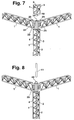
- FIGS. 6 to 8 are initially linked to the type of fastening according to FIG. 2 on. 7 shows the connection head 29, on which in the 2 explained two lattice girders via the coupling means 25 and the triangular plates 24 are mounted transversely.
- this one Connection head 29 with its lower plug shown in FIG. 2 36 into a receiving opening 37 of a triangular plate shown in FIG. 6 24 inserted, here as the top end a lattice girder is used, which is used as a pillar.
- Three the lattice girders according to the invention thus form according to FIG. 7 (or 8) a corner of the room.
- FIG. 7 or 8 a corner of the room.
- connection head 29 on its the plug 36 facing away from the side with an annular flange 39 is, which has a central opening 38, in which now in turn a plug 40 is insertable and attachable to one Triangular plate 24 is attached protruding on the front side according to FIG. 6. It In this way, as shown in FIG. 7, it becomes possible to use the one serving as a pedestal Extend lattice girder axially upwards.
- connection head 29 assign the previously mentioned plug pin 40 and with it Help a known profile column 41 with an octagonal cross section and with grooves in the manner of the grooves 28 of the connection head 29.
- a known profile column 41 with an octagonal cross section and with grooves in the manner of the grooves 28 of the connection head 29.
- Figures 9 and 10 show two examples of the use of the lattice girders in connection with other trade fair construction system parts, such as them are already on the market.
- FIG. 9 shows two examples of the use of the lattice girders in connection with other trade fair construction system parts, such as them are already on the market.
- FIG. 9 shows several lattice girders, now with the reference number 42 are provided.
- Three of these lattice girders 42 are on Stand columns 44 of commercial type attached, which with a top - additionally clad in the exemplary embodiment - connection head 29 are provided.
- the coupling means 25 are on this connection head and hooked the lattice girders 42 over this and the triangular plates 24.
- These lattice girders and the columns 44 are commercially available Stand columns 41 and corresponding wall panels 45 to that shown Stand added.
- Fig. 10 shows that e.g. with the help of three lattice girders 42 vaulted Can produce ceiling structures if appropriate and already on the market arc parts 43 on the open Slits of the chambers 20 (Fig. 3) of the hollow profiles 3 and 2 arranged become.
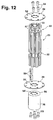
- FIG. 11 shows a connection head 29 which, as also with reference to 12 and 13 will be explained, from a tubular hollow profile consists of axially extending slots 50 on the outer circumference (or grooves 28 according to FIG. 2) is provided, which also extends axially Chambers 51 open.
- These hollow chambers 51 are designed that they accommodate the suspension heads 31 of the bolts 27 can.
- Carriers for example carriers in which the screw bolts 27 with two parallel profile tubes that are aligned with each other are connected by a flat grid. On in this way the connection of flat lattice girders would be possible.
- Fig. 11, but in particular Fig. 12 clearly show that the columnar Pipe section of the connection head 29 with two at a distance mutually extending annular grooves 30 is interrupted, the axial Dimension is large enough to the hanging heads 31 in the radial direction to insert on the axis of the pipe section of the connection head 29 and then be able to move axially downward into the chambers 51.
- 11 and 12 also show that the pipe section of the connection head Completed at the top and bottom by an annular flange 39 is that with the help of screws 53 directly at the end of the pipe section is attached.
- the screws 53 grip through recesses 54 of the ring flange 39 and can in Engage inner grooves 55 of the pipe section and screwed there become.
- the lower ring flange 39 can be attached in the same way, on which also a hollow cylindrical connector 36 with a screwed end plate 56 in the same manner can be, here also the screws 53 by appropriate Recesses 54 'can grip.
- connection head 29 can therefore be used universally.
Landscapes
- Engineering & Computer Science (AREA)
- Architecture (AREA)
- Civil Engineering (AREA)
- Structural Engineering (AREA)
- Rod-Shaped Construction Members (AREA)
- Joining Of Building Structures In Genera (AREA)
- Bridges Or Land Bridges (AREA)
- Superconductors And Manufacturing Methods Therefor (AREA)
- Food-Manufacturing Devices (AREA)
- Incineration Of Waste (AREA)
Abstract
Description
- Fig. 1
- die schematische perspektivische Darstellung eines Gitterträgers mit zwei an seinen Stirnenden anzuordnenden Dreiecksplatten,
- Fig. 2
- ein Ende eines Gitterträgers, dessen Stirnende eine Dreiecksplatte mit Kupplungsmitteln zum Verbinden mit einem säulenartigen Anschlusskopf nach der Erfindung aufweist,
- Fig. 3
- die Darstellung eines Querschnittes durch den Gitterträger der Fig. 1 mit eingeschobenen Dekorationsplatten und Verschlussleisten,
- Fig. 4
- die Teildarstellung eines Gitterträgers nach der Erfindung, an dem eine Elektroinstallationsleiste mit einem Scheinwerfer angebracht ist,
- Fig. 5
- den Gitterträger nach der Erfindung mit allseitig angeordneten Dekorationsplatten und integrierten Beleuchtungsmitteln,
- Fig. 6
- die Ausgestaltung eines Gitterträgers als Standsäule mit entsprechend ausgebildeten stirnseitigen Dreiecksplatten,
- Fig. 7
- den als Standsäule verwendeten Gitterträger der Fig. 6 mit einem aufgesetzten Anschlusskopf nach Fig. 2 und zwei daran angeordneten, als Querträger dienenden Gitterträgern, sowie mit der Möglichkeit eines axial aufsetzbaren weiteren Gitterträgers,
- Fig. 8
- eine Ausgestaltung ähnlich Fig. 7, bei der jedoch anstelle eines weiteren Gitterträgers eine bekannte Standsäule axial zu dem ersten, als Standsäule dienenden Gitterträger vorgesehen wird,
- Fig. 9
- die schematische Darstellung des Einsatzes mehrerer Gitterträger zum Aufbau eines Messestandes,
- Fig. 10
- die schematische Darstellung der Verwendung von Gitterträgern zum Aufbau eines Deckengewölbes,
- Fig. 11
- eine vergrößerte Darstellung des Anschlusskopfes aus der Darstellung der Fig. 2,
- Fig. 12
- eine Explosionsdarstellung des Anschlusskopfes der Fig. 11, und
- Fig. 13
- einen vergrößert dargestellten Teilschnitt durch das Profil des Anschlusskopfes nach den Fig. 11 und 12.
Claims (6)
- Anschlusskopf für Gitterträger zur Herstellung mobiler Bauten, insbesondere von Messe- und Ausstellungsständen, bestehend aus einem Rohrabschnitt (29) mit am Umfang verteilten, axial verlaufenden Nuten (50) zum Einhängen von Spanngliedern von Querträgern (42), dadurch gekennzeichnet, dass die Einhängenuten durch ringförmige Nuten (30) unterbrochen sind, die zum radialen Einführen von Einhängeköpfen (31) dienen, die mit den Querträgern (42) verbunden sind.
- Anschlusskopf nach Anspruch 1, dadurch gekennzeichnet, dass der Rohrabschnitt (29) an beiden Stirnseiten mit Ringflanschen (39) abgeschlossen ist.
- Anschlusskopf nach Anspruch 2, dadurch gekennzeichnet, dass der Rohrabschnitt (29) mit Innennuten (55) versehen ist, die als Befestigungsöffnungen für Schrauben (53) zur Anbringung der Ringflansche (39) dienen.
- Anschlusskopf nach Anspruch 1, dadurch gekennzeichnet, dass ein hohlzylindrisches Anschlussstück (36) mit einer stirnseitigen Abschlussplatte (56) vorgesehen ist, die an einen Ringflansch (39) ansetzbar ist.
- Anschlusskopf nach Anspruch 1, dadurch gekennzeichnet, dass parallel zu den Einhängenuten (50) und radial innerhalb derselben weitere Nuten (57) zur Anbringung von handelsüblichen Spannschlössern vorgesehen sind.
- Anschlusskopf nach Anspruch 1, dadurch gekennzeichnet, dass Nutensteine (58) zum Einführen in die Einhängenuten (50) und zur Höheneinstellung der Einhängeköpfe (31) vorgesehen sind.
Applications Claiming Priority (3)
| Application Number | Priority Date | Filing Date | Title |
|---|---|---|---|
| DE19714996 | 1997-04-10 | ||
| DE19714996A DE19714996C2 (de) | 1997-04-10 | 1997-04-10 | Gitterträger zur Herstellung mobiler Bauten |
| EP98912422A EP0973985B1 (de) | 1997-04-10 | 1998-02-28 | Gitterträger zur herstellung mobiler bauten |
Related Parent Applications (1)
| Application Number | Title | Priority Date | Filing Date |
|---|---|---|---|
| EP98912422A Division EP0973985B1 (de) | 1997-04-10 | 1998-02-28 | Gitterträger zur herstellung mobiler bauten |
Publications (3)
| Publication Number | Publication Date |
|---|---|
| EP1231340A2 true EP1231340A2 (de) | 2002-08-14 |
| EP1231340A3 EP1231340A3 (de) | 2003-03-19 |
| EP1231340B1 EP1231340B1 (de) | 2005-10-12 |
Family
ID=7826123
Family Applications (2)
| Application Number | Title | Priority Date | Filing Date |
|---|---|---|---|
| EP02011009A Expired - Lifetime EP1231340B1 (de) | 1997-04-10 | 1998-02-28 | Anschlusskopf für Gitterträger zur Herstellung mobiler Bauten |
| EP98912422A Expired - Lifetime EP0973985B1 (de) | 1997-04-10 | 1998-02-28 | Gitterträger zur herstellung mobiler bauten |
Family Applications After (1)
| Application Number | Title | Priority Date | Filing Date |
|---|---|---|---|
| EP98912422A Expired - Lifetime EP0973985B1 (de) | 1997-04-10 | 1998-02-28 | Gitterträger zur herstellung mobiler bauten |
Country Status (8)
| Country | Link |
|---|---|
| EP (2) | EP1231340B1 (de) |
| CN (2) | CN1302184C (de) |
| AT (1) | ATE238471T1 (de) |
| DE (3) | DE19714996C2 (de) |
| ES (2) | ES2196555T3 (de) |
| PL (1) | PL196451B1 (de) |
| SK (1) | SK286207B6 (de) |
| WO (1) | WO1998045552A1 (de) |
Cited By (1)
| Publication number | Priority date | Publication date | Assignee | Title |
|---|---|---|---|---|
| EP4512973A1 (de) * | 2023-08-24 | 2025-02-26 | Stoyanov, Damian Vassilev | Einstückiges bauknüppelsystemprofil bestehend aus zwei mit einer bahn verbundenen hohlflanschen zur montage von trägern, büssen und räumlichen strukturen und stiftsystemprofilmontagekit mit einem solchen integrierten stiftsystemprofil |
Families Citing this family (14)
| Publication number | Priority date | Publication date | Assignee | Title |
|---|---|---|---|---|
| ES2229592T3 (es) | 1998-07-30 | 2005-04-16 | Octanorm-Vertriebs-Gmbh Fur Bauelemente | Sistema de construccion. |
| DE19834372C1 (de) | 1998-07-30 | 1999-10-28 | Octanorm Vertriebsgesellschaft | Profilrohr für die Herstellung kurzzeitiger Aufbauten |
| US7779599B2 (en) | 2004-03-31 | 2010-08-24 | Safway Services, Llc | Articulating work platform support system, work platform system, and methods of use thereof |
| DE102004023727A1 (de) * | 2004-05-11 | 2005-12-22 | Mero-Tsk International Gmbh & Co.Kg | Flächentragwerk |
| CN100366855C (zh) * | 2004-08-20 | 2008-02-06 | 中国建筑第八工程局第一建筑公司青岛分公司 | 倾斜三棱锥形桁架式框架结构及其制作、安装、测量方法 |
| DE102007054205B4 (de) * | 2007-11-12 | 2012-11-22 | Ulrich Leiseder | Stabtragwerke |
| DE102009050736A1 (de) * | 2009-10-27 | 2011-04-28 | Airbus Operations Gmbh | Befestigungsanordnung zum Befestigen einer Baueinheit an einem Flugzeugrumpf |
| CN102392492A (zh) * | 2011-09-28 | 2012-03-28 | 江苏科技大学 | 一种格构式钢结构节点连接装置 |
| CN103866861B (zh) * | 2014-03-20 | 2016-05-25 | 北京工业大学 | 一种节点刚接的模块化装配式钢结构预应力中心支撑体系 |
| CN106812245B (zh) * | 2017-01-23 | 2019-05-28 | 合肥饰界金属制品有限公司 | 桁架 |
| BE1025724B1 (nl) | 2017-11-20 | 2019-06-24 | Willy Bruyninckx | Inrichting voor het versterken en aankleden van spanten en werkwijze waarbij zulke inrichting wordt toegepast. |
| DE102021115948A1 (de) * | 2021-06-21 | 2022-12-22 | Doka Gmbh | Bolzenverbinder |
| NO347585B1 (en) * | 2021-09-30 | 2024-01-22 | Produktif Norway As | Hybrid joint assembly |
| CN117418611A (zh) * | 2023-03-16 | 2024-01-19 | 中建二局阳光智造有限公司 | 一种多角度y字钢柱与钢梁节点构造及成型方法 |
Citations (1)
| Publication number | Priority date | Publication date | Assignee | Title |
|---|---|---|---|---|
| EP0393090A1 (de) | 1988-01-12 | 1990-10-24 | Octanorm Vertriebs Gmbh | Bausatz zur herstellung von tragwerken. |
Family Cites Families (21)
| Publication number | Priority date | Publication date | Assignee | Title |
|---|---|---|---|---|
| US3111207A (en) * | 1960-06-06 | 1963-11-19 | Ralph E Braddon | Bar joists |
| EP0126657A3 (de) * | 1983-03-25 | 1984-12-27 | Philippe Andre Pierre Meyer | Schnell- und Umkehrbare Montierungssysteme aus verschiedene vorgefertigten Bauelementen zusammengestelt |
| DE8616463U1 (de) * | 1986-06-20 | 1986-08-14 | Fink, Dieter, 71711 Steinheim | Bausatz für Messestände und dgl. |
| US4730739A (en) * | 1987-02-04 | 1988-03-15 | Semerau Jr Robert J | Open framework merchandise display system |
| DE3726503A1 (de) * | 1987-08-08 | 1989-02-23 | Schoenfeld Hans Victor | Bauelement |
| CN87214614U (zh) * | 1987-10-30 | 1988-08-17 | 曹登敬 | 万向多功能齿碗扣固定接头 |
| DE3907770C1 (en) * | 1989-03-10 | 1990-06-13 | Karl 6951 Binau De Mildner | Exhibition system for shop construction work, fair construction work, museums and the like |
| US5119613A (en) * | 1989-03-21 | 1992-06-09 | Owen Brown Group Ltd. | Composite beam, connector and construction |
| DE9116499U1 (de) * | 1990-06-15 | 1992-12-03 | Mero-Raumstruktur GmbH & Co Würzburg, 8700 Würzburg | Stab mit wenigstens einer Längsnut für Fachwerke oder Raumfachwerke |
| DE9010562U1 (de) * | 1990-07-13 | 1991-11-14 | Xylo Buchstaben Rudolf Prien GmbH, 8000 München | Raumfachwerk |
| DE4126805A1 (de) * | 1991-08-09 | 1993-02-11 | Leuna Werke Ag | Verfahren zur herstellung von granuliertem ammoniumsulfat |
| DE4132447C2 (de) * | 1991-09-28 | 1994-02-10 | Dellen Wilhelm Von Der Dipl Vo | Anordnung zur Erstellung von Wand- und/oder Deckenkonstruktionen, insbesondere im Messebau |
| US5271204A (en) * | 1992-01-21 | 1993-12-21 | Wolf Morris A | Lightweight display post and method of making same |
| DE4221387C2 (de) * | 1992-06-30 | 1996-02-29 | Mero Raumstruktur Gmbh & Co | Gitterträger, insbesondere für Raumfachwerke |
| DE4229406A1 (de) * | 1992-09-03 | 1994-03-10 | F & T Form & Technik | Knotenstück zur Verbindung von Streben eines Messe- oder Ladenbaugerüsts |
| US5356234A (en) * | 1992-10-26 | 1994-10-18 | 506567 Ontario Limited | Separable joint for arm and hub constructions |
| DE4315779A1 (de) * | 1993-05-12 | 1994-11-17 | Bernd Klein | Tragsystem, insbesondere für Verkehrs- und Wegweiseinrichtungen |
| FR2708302B1 (fr) * | 1993-06-28 | 1995-10-20 | Eck Bernard | Structure de montage rapide à base de profilés préférentiellement en aluminium. |
| JP3434372B2 (ja) * | 1993-10-30 | 2003-08-04 | 株式会社豊夢 | トラス用接合治具 |
| DE29700795U1 (de) * | 1996-01-25 | 1997-03-27 | Klein, Bernd, 35687 Dillenburg | Tragelement zur Verwendung bei einem Fachwerkträger |
| DE19610638A1 (de) * | 1996-03-07 | 1997-09-11 | Gaertner August Fa | Gitterträger |
-
1997
- 1997-04-10 DE DE19714996A patent/DE19714996C2/de not_active Expired - Fee Related
-
1998
- 1998-02-28 ES ES98912422T patent/ES2196555T3/es not_active Expired - Lifetime
- 1998-02-28 CN CNB021220107A patent/CN1302184C/zh not_active Expired - Fee Related
- 1998-02-28 PL PL336113A patent/PL196451B1/pl not_active IP Right Cessation
- 1998-02-28 DE DE59813108T patent/DE59813108D1/de not_active Expired - Lifetime
- 1998-02-28 WO PCT/EP1998/001143 patent/WO1998045552A1/de not_active Ceased
- 1998-02-28 DE DE59808072T patent/DE59808072D1/de not_active Expired - Lifetime
- 1998-02-28 EP EP02011009A patent/EP1231340B1/de not_active Expired - Lifetime
- 1998-02-28 CN CN98804024.7A patent/CN1095914C/zh not_active Expired - Fee Related
- 1998-02-28 SK SK1354-99A patent/SK286207B6/sk not_active IP Right Cessation
- 1998-02-28 AT AT98912422T patent/ATE238471T1/de not_active IP Right Cessation
- 1998-02-28 ES ES02011009T patent/ES2247221T3/es not_active Expired - Lifetime
- 1998-02-28 EP EP98912422A patent/EP0973985B1/de not_active Expired - Lifetime
Patent Citations (1)
| Publication number | Priority date | Publication date | Assignee | Title |
|---|---|---|---|---|
| EP0393090A1 (de) | 1988-01-12 | 1990-10-24 | Octanorm Vertriebs Gmbh | Bausatz zur herstellung von tragwerken. |
Cited By (1)
| Publication number | Priority date | Publication date | Assignee | Title |
|---|---|---|---|---|
| EP4512973A1 (de) * | 2023-08-24 | 2025-02-26 | Stoyanov, Damian Vassilev | Einstückiges bauknüppelsystemprofil bestehend aus zwei mit einer bahn verbundenen hohlflanschen zur montage von trägern, büssen und räumlichen strukturen und stiftsystemprofilmontagekit mit einem solchen integrierten stiftsystemprofil |
Also Published As
| Publication number | Publication date |
|---|---|
| WO1998045552A1 (de) | 1998-10-15 |
| EP0973985A1 (de) | 2000-01-26 |
| ES2247221T3 (es) | 2006-03-01 |
| PL336113A1 (en) | 2000-06-05 |
| SK135499A3 (en) | 2000-06-12 |
| PL196451B1 (pl) | 2008-01-31 |
| CN1302184C (zh) | 2007-02-28 |
| DE59808072D1 (de) | 2003-05-28 |
| ATE238471T1 (de) | 2003-05-15 |
| CN1492116A (zh) | 2004-04-28 |
| EP0973985B1 (de) | 2003-04-23 |
| DE19714996A1 (de) | 1998-10-29 |
| CN1095914C (zh) | 2002-12-11 |
| EP1231340A3 (de) | 2003-03-19 |
| ES2196555T3 (es) | 2003-12-16 |
| DE59813108D1 (de) | 2006-02-23 |
| HK1027142A1 (en) | 2001-01-05 |
| SK286207B6 (sk) | 2008-05-06 |
| HK1049196A1 (en) | 2003-05-02 |
| CN1252115A (zh) | 2000-05-03 |
| EP1231340B1 (de) | 2005-10-12 |
| DE19714996C2 (de) | 2001-01-25 |
Similar Documents
| Publication | Publication Date | Title |
|---|---|---|
| EP0393090B1 (de) | Bausatz zur herstellung von tragwerken | |
| EP0973985B1 (de) | Gitterträger zur herstellung mobiler bauten | |
| EP0616088B1 (de) | Ebener oder räumlicher Deckenrost aus Stäben und Knotenstücken, insbesondere begehbarer Deckenrost | |
| DE3303190C2 (de) | Bausatz zur Erstellung mobiler Bauten, insbesondere für Messe- und Ausstellungsbauten | |
| DE3342616A1 (de) | Profilrohr fuer die herstellung von leicht montier- und wieder demontierbaren aufbauten | |
| DE3704831C2 (de) | ||
| DE3620619A1 (de) | Bausatz fuer messestaende und dergleichen | |
| DE2350129C3 (de) | Vorrichtung zur Errichtung von umfangsgeschlossenen Betonbauten | |
| DE69403226T2 (de) | Modulares bauelement für ausstellungsräume | |
| EP1081300A2 (de) | Bauwerk | |
| EP0098962B1 (de) | Montagegerüst für Schalungen für Rundbauten aus Beton od.dgl. | |
| DE3617445C2 (de) | ||
| DE3641742C2 (de) | ||
| DE2312510C3 (de) | Gebäudeskelett aus Fertigteilen | |
| DE2416809A1 (de) | Bauelementensatz fuer ein skelett-bausystem, insbesondere aus aluminiumprofilen | |
| EP1030005A2 (de) | Deckenanordnung, und Verfahren zu ihrer Herstellung | |
| AT324645B (de) | Unterdecke | |
| DE9101423U1 (de) | Bausatz | |
| DE202017106868U1 (de) | Deckensystem mit Profilelement für abgehängte Decken | |
| DE2751520A1 (de) | Schalldaemmende verkleidung | |
| DE9308647U1 (de) | Winkelprofil zur Errichtung kurzzeitiger Aufbauten | |
| DE3423562A1 (de) | Bauelement fuer innenausbau-, insbesondere messe- und ladenbauzwecke | |
| EP0337115A2 (de) | Leuchtenträger-Anordnung | |
| DE20023596U1 (de) | Deckenanordnung | |
| DE20301896U1 (de) | Modulare Gestellkonstruktion und ein daraus hergestelltes Möbel |
Legal Events
| Date | Code | Title | Description |
|---|---|---|---|
| PUAI | Public reference made under article 153(3) epc to a published international application that has entered the european phase |
Free format text: ORIGINAL CODE: 0009012 |
|
| 17P | Request for examination filed |
Effective date: 20020517 |
|
| AC | Divisional application: reference to earlier application |
Ref document number: 973985 Country of ref document: EP |
|
| AK | Designated contracting states |
Kind code of ref document: A2 Designated state(s): AT BE CH DE DK ES FI FR GB GR IE IT LI NL PT SE |
|
| PUAL | Search report despatched |
Free format text: ORIGINAL CODE: 0009013 |
|
| AK | Designated contracting states |
Kind code of ref document: A3 Designated state(s): AT BE CH DE DK ES FI FR GB GR IE IT LI NL PT SE |
|
| RIC1 | Information provided on ipc code assigned before grant |
Ipc: 7E 04B 1/19 B Ipc: 7E 04H 1/12 A Ipc: 7E 04C 3/08 B |
|
| AKX | Designation fees paid |
Designated state(s): DE ES GB IT NL |
|
| GRAP | Despatch of communication of intention to grant a patent |
Free format text: ORIGINAL CODE: EPIDOSNIGR1 |
|
| GRAS | Grant fee paid |
Free format text: ORIGINAL CODE: EPIDOSNIGR3 |
|
| GRAA | (expected) grant |
Free format text: ORIGINAL CODE: 0009210 |
|
| AC | Divisional application: reference to earlier application |
Ref document number: 0973985 Country of ref document: EP Kind code of ref document: P |
|
| AK | Designated contracting states |
Kind code of ref document: B1 Designated state(s): DE ES GB IT NL |
|
| REG | Reference to a national code |
Ref country code: GB Ref legal event code: FG4D Free format text: NOT ENGLISH |
|
| GBT | Gb: translation of ep patent filed (gb section 77(6)(a)/1977) |
Effective date: 20051202 |
|
| REF | Corresponds to: |
Ref document number: 59813108 Country of ref document: DE Date of ref document: 20060223 Kind code of ref document: P |
|
| REG | Reference to a national code |
Ref country code: ES Ref legal event code: FG2A Ref document number: 2247221 Country of ref document: ES Kind code of ref document: T3 |
|
| REG | Reference to a national code |
Ref country code: HK Ref legal event code: GR Ref document number: 1049196 Country of ref document: HK |
|
| PLBE | No opposition filed within time limit |
Free format text: ORIGINAL CODE: 0009261 |
|
| STAA | Information on the status of an ep patent application or granted ep patent |
Free format text: STATUS: NO OPPOSITION FILED WITHIN TIME LIMIT |
|
| 26N | No opposition filed |
Effective date: 20060713 |
|
| PGFP | Annual fee paid to national office [announced via postgrant information from national office to epo] |
Ref country code: ES Payment date: 20100219 Year of fee payment: 13 |
|
| PGFP | Annual fee paid to national office [announced via postgrant information from national office to epo] |
Ref country code: IT Payment date: 20100226 Year of fee payment: 13 |
|
| PGFP | Annual fee paid to national office [announced via postgrant information from national office to epo] |
Ref country code: GB Payment date: 20100219 Year of fee payment: 13 |
|
| PGFP | Annual fee paid to national office [announced via postgrant information from national office to epo] |
Ref country code: NL Payment date: 20100218 Year of fee payment: 13 |
|
| REG | Reference to a national code |
Ref country code: NL Ref legal event code: V1 Effective date: 20110901 |
|
| GBPC | Gb: european patent ceased through non-payment of renewal fee |
Effective date: 20110228 |
|
| PG25 | Lapsed in a contracting state [announced via postgrant information from national office to epo] |
Ref country code: IT Free format text: LAPSE BECAUSE OF NON-PAYMENT OF DUE FEES Effective date: 20110228 Ref country code: NL Free format text: LAPSE BECAUSE OF NON-PAYMENT OF DUE FEES Effective date: 20110901 |
|
| PG25 | Lapsed in a contracting state [announced via postgrant information from national office to epo] |
Ref country code: GB Free format text: LAPSE BECAUSE OF NON-PAYMENT OF DUE FEES Effective date: 20110228 |
|
| REG | Reference to a national code |
Ref country code: ES Ref legal event code: FD2A Effective date: 20120411 |
|
| PG25 | Lapsed in a contracting state [announced via postgrant information from national office to epo] |
Ref country code: ES Free format text: LAPSE BECAUSE OF NON-PAYMENT OF DUE FEES Effective date: 20110301 |
|
| PGFP | Annual fee paid to national office [announced via postgrant information from national office to epo] |
Ref country code: DE Payment date: 20140217 Year of fee payment: 17 |
|
| REG | Reference to a national code |
Ref country code: DE Ref legal event code: R119 Ref document number: 59813108 Country of ref document: DE |
|
| PG25 | Lapsed in a contracting state [announced via postgrant information from national office to epo] |
Ref country code: DE Free format text: LAPSE BECAUSE OF NON-PAYMENT OF DUE FEES Effective date: 20150901 |