EP1231352A2 - Procédé et dispositif de fabrication de profilés de croisillon entaillés pourvus de deux couches de finition - Google Patents
Procédé et dispositif de fabrication de profilés de croisillon entaillés pourvus de deux couches de finition Download PDFInfo
- Publication number
- EP1231352A2 EP1231352A2 EP02002983A EP02002983A EP1231352A2 EP 1231352 A2 EP1231352 A2 EP 1231352A2 EP 02002983 A EP02002983 A EP 02002983A EP 02002983 A EP02002983 A EP 02002983A EP 1231352 A2 EP1231352 A2 EP 1231352A2
- Authority
- EP
- European Patent Office
- Prior art keywords
- muntin
- muntin bar
- finish
- stock
- sheet material
- Prior art date
- Legal status (The legal status is an assumption and is not a legal conclusion. Google has not performed a legal analysis and makes no representation as to the accuracy of the status listed.)
- Withdrawn
Links
Images



Classifications
-
- B—PERFORMING OPERATIONS; TRANSPORTING
- B21—MECHANICAL METAL-WORKING WITHOUT ESSENTIALLY REMOVING MATERIAL; PUNCHING METAL
- B21C—MANUFACTURE OF METAL SHEETS, WIRE, RODS, TUBES, PROFILES OR LIKE SEMI-MANUFACTURED PRODUCTS OTHERWISE THAN BY ROLLING; AUXILIARY OPERATIONS USED IN CONNECTION WITH METAL-WORKING WITHOUT ESSENTIALLY REMOVING MATERIAL
- B21C37/00—Manufacture of metal sheets, rods, wire, tubes, profiles or like semi-manufactured products, not otherwise provided for; Manufacture of tubes of special shape
- B21C37/06—Manufacture of metal sheets, rods, wire, tubes, profiles or like semi-manufactured products, not otherwise provided for; Manufacture of tubes of special shape of tubes or metal hoses; Combined procedures for making tubes, e.g. for making multi-wall tubes
- B21C37/15—Making tubes of special shape; Making tube fittings
- B21C37/155—Making tubes with non-circular section
-
- B—PERFORMING OPERATIONS; TRANSPORTING
- B21—MECHANICAL METAL-WORKING WITHOUT ESSENTIALLY REMOVING MATERIAL; PUNCHING METAL
- B21D—WORKING OR PROCESSING OF SHEET METAL OR METAL TUBES, RODS OR PROFILES WITHOUT ESSENTIALLY REMOVING MATERIAL; PUNCHING METAL
- B21D5/00—Bending sheet metal along straight lines, e.g. to form simple curves
- B21D5/06—Bending sheet metal along straight lines, e.g. to form simple curves by drawing procedure making use of dies or forming-rollers, e.g. making profiles
- B21D5/08—Bending sheet metal along straight lines, e.g. to form simple curves by drawing procedure making use of dies or forming-rollers, e.g. making profiles making use of forming-rollers
-
- B—PERFORMING OPERATIONS; TRANSPORTING
- B21—MECHANICAL METAL-WORKING WITHOUT ESSENTIALLY REMOVING MATERIAL; PUNCHING METAL
- B21D—WORKING OR PROCESSING OF SHEET METAL OR METAL TUBES, RODS OR PROFILES WITHOUT ESSENTIALLY REMOVING MATERIAL; PUNCHING METAL
- B21D5/00—Bending sheet metal along straight lines, e.g. to form simple curves
- B21D5/06—Bending sheet metal along straight lines, e.g. to form simple curves by drawing procedure making use of dies or forming-rollers, e.g. making profiles
- B21D5/08—Bending sheet metal along straight lines, e.g. to form simple curves by drawing procedure making use of dies or forming-rollers, e.g. making profiles making use of forming-rollers
- B21D5/086—Bending sheet metal along straight lines, e.g. to form simple curves by drawing procedure making use of dies or forming-rollers, e.g. making profiles making use of forming-rollers for obtaining closed hollow profiles
-
- B—PERFORMING OPERATIONS; TRANSPORTING
- B32—LAYERED PRODUCTS
- B32B—LAYERED PRODUCTS, i.e. PRODUCTS BUILT-UP OF STRATA OF FLAT OR NON-FLAT, e.g. CELLULAR OR HONEYCOMB, FORM
- B32B38/00—Ancillary operations in connection with laminating processes
- B32B38/18—Handling of layers or the laminate
- B32B38/1825—Handling of layers or the laminate characterised by the control or constructional features of devices for tensioning, stretching or registration
- B32B38/1833—Positioning, e.g. registration or centering
- B32B38/1841—Positioning, e.g. registration or centering during laying up
-
- E—FIXED CONSTRUCTIONS
- E06—DOORS, WINDOWS, SHUTTERS, OR ROLLER BLINDS IN GENERAL; LADDERS
- E06B—FIXED OR MOVABLE CLOSURES FOR OPENINGS IN BUILDINGS, VEHICLES, FENCES OR LIKE ENCLOSURES IN GENERAL, e.g. DOORS, WINDOWS, BLINDS, GATES
- E06B3/00—Window sashes, door leaves, or like elements for closing wall or like openings; Layout of fixed or moving closures, e.g. windows in wall or like openings; Features of rigidly-mounted outer frames relating to the mounting of wing frames
- E06B3/66—Units comprising two or more parallel glass or like panes permanently secured together
- E06B3/6604—Units comprising two or more parallel glass or like panes permanently secured together comprising false glazing bars or similar decorations between the panes
-
- E—FIXED CONSTRUCTIONS
- E06—DOORS, WINDOWS, SHUTTERS, OR ROLLER BLINDS IN GENERAL; LADDERS
- E06B—FIXED OR MOVABLE CLOSURES FOR OPENINGS IN BUILDINGS, VEHICLES, FENCES OR LIKE ENCLOSURES IN GENERAL, e.g. DOORS, WINDOWS, BLINDS, GATES
- E06B3/00—Window sashes, door leaves, or like elements for closing wall or like openings; Layout of fixed or moving closures, e.g. windows in wall or like openings; Features of rigidly-mounted outer frames relating to the mounting of wing frames
- E06B3/66—Units comprising two or more parallel glass or like panes permanently secured together
- E06B3/663—Elements for spacing panes
- E06B3/667—Connectors therefor
-
- E—FIXED CONSTRUCTIONS
- E06—DOORS, WINDOWS, SHUTTERS, OR ROLLER BLINDS IN GENERAL; LADDERS
- E06B—FIXED OR MOVABLE CLOSURES FOR OPENINGS IN BUILDINGS, VEHICLES, FENCES OR LIKE ENCLOSURES IN GENERAL, e.g. DOORS, WINDOWS, BLINDS, GATES
- E06B3/00—Window sashes, door leaves, or like elements for closing wall or like openings; Layout of fixed or moving closures, e.g. windows in wall or like openings; Features of rigidly-mounted outer frames relating to the mounting of wing frames
- E06B3/66—Units comprising two or more parallel glass or like panes permanently secured together
- E06B3/673—Assembling the units
- E06B3/67304—Preparing rigid spacer members before assembly
-
- B—PERFORMING OPERATIONS; TRANSPORTING
- B32—LAYERED PRODUCTS
- B32B—LAYERED PRODUCTS, i.e. PRODUCTS BUILT-UP OF STRATA OF FLAT OR NON-FLAT, e.g. CELLULAR OR HONEYCOMB, FORM
- B32B2311/00—Metals, their alloys or their compounds
-
- B—PERFORMING OPERATIONS; TRANSPORTING
- B32—LAYERED PRODUCTS
- B32B—LAYERED PRODUCTS, i.e. PRODUCTS BUILT-UP OF STRATA OF FLAT OR NON-FLAT, e.g. CELLULAR OR HONEYCOMB, FORM
- B32B2451/00—Decorative or ornamental articles
-
- B—PERFORMING OPERATIONS; TRANSPORTING
- B32—LAYERED PRODUCTS
- B32B—LAYERED PRODUCTS, i.e. PRODUCTS BUILT-UP OF STRATA OF FLAT OR NON-FLAT, e.g. CELLULAR OR HONEYCOMB, FORM
- B32B37/00—Methods or apparatus for laminating, e.g. by curing or by ultrasonic bonding
- B32B37/02—Methods or apparatus for laminating, e.g. by curing or by ultrasonic bonding characterised by a sequence of laminating steps, e.g. by adding new layers at consecutive laminating stations
- B32B37/025—Transfer laminating
-
- E—FIXED CONSTRUCTIONS
- E06—DOORS, WINDOWS, SHUTTERS, OR ROLLER BLINDS IN GENERAL; LADDERS
- E06B—FIXED OR MOVABLE CLOSURES FOR OPENINGS IN BUILDINGS, VEHICLES, FENCES OR LIKE ENCLOSURES IN GENERAL, e.g. DOORS, WINDOWS, BLINDS, GATES
- E06B3/00—Window sashes, door leaves, or like elements for closing wall or like openings; Layout of fixed or moving closures, e.g. windows in wall or like openings; Features of rigidly-mounted outer frames relating to the mounting of wing frames
- E06B3/66—Units comprising two or more parallel glass or like panes permanently secured together
- E06B3/673—Assembling the units
- E06B3/67304—Preparing rigid spacer members before assembly
- E06B3/67321—Covering spacer elements, e.g. with sealants
-
- Y—GENERAL TAGGING OF NEW TECHNOLOGICAL DEVELOPMENTS; GENERAL TAGGING OF CROSS-SECTIONAL TECHNOLOGIES SPANNING OVER SEVERAL SECTIONS OF THE IPC; TECHNICAL SUBJECTS COVERED BY FORMER USPC CROSS-REFERENCE ART COLLECTIONS [XRACs] AND DIGESTS
- Y10—TECHNICAL SUBJECTS COVERED BY FORMER USPC
- Y10T—TECHNICAL SUBJECTS COVERED BY FORMER US CLASSIFICATION
- Y10T29/00—Metal working
- Y10T29/49—Method of mechanical manufacture
- Y10T29/49789—Obtaining plural product pieces from unitary workpiece
- Y10T29/49798—Dividing sequentially from leading end, e.g., by cutting or breaking
-
- Y—GENERAL TAGGING OF NEW TECHNOLOGICAL DEVELOPMENTS; GENERAL TAGGING OF CROSS-SECTIONAL TECHNOLOGIES SPANNING OVER SEVERAL SECTIONS OF THE IPC; TECHNICAL SUBJECTS COVERED BY FORMER USPC CROSS-REFERENCE ART COLLECTIONS [XRACs] AND DIGESTS
- Y10—TECHNICAL SUBJECTS COVERED BY FORMER USPC
- Y10T—TECHNICAL SUBJECTS COVERED BY FORMER US CLASSIFICATION
- Y10T29/00—Metal working
- Y10T29/51—Plural diverse manufacturing apparatus including means for metal shaping or assembling
- Y10T29/5136—Separate tool stations for selective or successive operation on work
- Y10T29/5137—Separate tool stations for selective or successive operation on work including assembling or disassembling station
- Y10T29/5142—Separate tool stations for selective or successive operation on work including assembling or disassembling station and means to sever work from supply
-
- Y—GENERAL TAGGING OF NEW TECHNOLOGICAL DEVELOPMENTS; GENERAL TAGGING OF CROSS-SECTIONAL TECHNOLOGIES SPANNING OVER SEVERAL SECTIONS OF THE IPC; TECHNICAL SUBJECTS COVERED BY FORMER USPC CROSS-REFERENCE ART COLLECTIONS [XRACs] AND DIGESTS
- Y10—TECHNICAL SUBJECTS COVERED BY FORMER USPC
- Y10T—TECHNICAL SUBJECTS COVERED BY FORMER US CLASSIFICATION
- Y10T29/00—Metal working
- Y10T29/51—Plural diverse manufacturing apparatus including means for metal shaping or assembling
- Y10T29/5136—Separate tool stations for selective or successive operation on work
- Y10T29/5137—Separate tool stations for selective or successive operation on work including assembling or disassembling station
- Y10T29/5143—Separate tool stations for selective or successive operation on work including assembling or disassembling station and means to machine product
-
- Y—GENERAL TAGGING OF NEW TECHNOLOGICAL DEVELOPMENTS; GENERAL TAGGING OF CROSS-SECTIONAL TECHNOLOGIES SPANNING OVER SEVERAL SECTIONS OF THE IPC; TECHNICAL SUBJECTS COVERED BY FORMER USPC CROSS-REFERENCE ART COLLECTIONS [XRACs] AND DIGESTS
- Y10—TECHNICAL SUBJECTS COVERED BY FORMER USPC
- Y10T—TECHNICAL SUBJECTS COVERED BY FORMER US CLASSIFICATION
- Y10T29/00—Metal working
- Y10T29/51—Plural diverse manufacturing apparatus including means for metal shaping or assembling
- Y10T29/5136—Separate tool stations for selective or successive operation on work
- Y10T29/5137—Separate tool stations for selective or successive operation on work including assembling or disassembling station
- Y10T29/5143—Separate tool stations for selective or successive operation on work including assembling or disassembling station and means to machine product
- Y10T29/5145—Separate tool stations for selective or successive operation on work including assembling or disassembling station and means to machine product to sever product to length
-
- Y—GENERAL TAGGING OF NEW TECHNOLOGICAL DEVELOPMENTS; GENERAL TAGGING OF CROSS-SECTIONAL TECHNOLOGIES SPANNING OVER SEVERAL SECTIONS OF THE IPC; TECHNICAL SUBJECTS COVERED BY FORMER USPC CROSS-REFERENCE ART COLLECTIONS [XRACs] AND DIGESTS
- Y10—TECHNICAL SUBJECTS COVERED BY FORMER USPC
- Y10T—TECHNICAL SUBJECTS COVERED BY FORMER US CLASSIFICATION
- Y10T29/00—Metal working
- Y10T29/51—Plural diverse manufacturing apparatus including means for metal shaping or assembling
- Y10T29/5196—Multiple station with conveyor
Definitions
- the present invention concerns muntin bars used for separating window panes of large size into smaller size panes to enhance the appearance of a window.
- Windows constructed from multiple glass panes utilized "muntins" or “muntin bars” to secure the edges of the individual glass panes within the window sash.
- muntins formed distinctive grid patterns that are associated with architectural styles of buildings containing the windows.
- Modern windows formed by insulating glass units utilize single glass lites separated by an insulating dead air space. Where a particular architectural "look" is desired, a grid of muntin bars is fixed in the dead air space between the glass lites to simulate a multi-pane window.
- Typical muntin bars for insulating glass units are formed from decoratively coated interfitted metal tubes. The grids are anchored to the insulating glass unit periphery.
- the muntin bar stock is produced by roll forming decoratively coated sheet material such as aluminum or steel, in a known manner. Various sizes of the sheet material are used to form different size muntin bar stock.
- the roll forming machine has a series of rolls configured to form sheet material into elongated tubular muntin bar stock.
- a window manufacturer purchases the muntin bar stock size(s) needed to produce insulating glass units.
- Apparatus disclosed in the aforementioned patent application also cuts the stock into lengths that are notched in appropriate locations for assembly into grids for incorporation into the insulating glass units.
- the residential window and door industry has witnessed an increased demand for internal decorative muntin bars contained in insulated glass units (IGUs) of their windows.
- IGUs insulated glass units
- This market demand for muntin bars has increased due to popular "colonial look” trends in the market.
- new construction and residential building codes requiring a common facade in local neighborhoods.
- a demand for so-called "two tone" muntin bars is on the rise.
- the two tone muntin bar assembly presents one appearance from the outside and a second appearance from inside the window.
- Two-tone muntin bars are offered today in many color combinations for both rectangular and contour style muntin bars.
- a two-tone muntin bar demands a premium price in the market place.
- One reason for the increased price of two tone muntin bars is the fact that automated manufacturing of two tone muntin bars using controlled notching, roll forming and severing has not occurred.
- the present invention concerns an automated method and apparatus for producing notched muntin bars from a supply of sheet material having first and second finishes.
- muntin bars having first and second finishes are provided that have one appearance when viewed from outside the window and a second appearance when viewed from inside the window.
- a supply of thin sheet material that has been treated to define first and second finishes on one side of the sheet material is provided. Sections of the material having the first finish and sections of the material having the second finish are removed from the sheet material.
- the sheet material is then formed into an elongated tubular muntin bar stock.
- the muntin bar stock has a first side having the first finish and a second side having the second finish.
- the muntin bar stock has notches in the first side that correspond to the removed sections of material having the first finish.
- the formed muntin bar stock has notches in its second side that correspond to the removed sections of material having the second finish.
- the muntin bar stock is severed at predetermined locations to form individual notched muntin bars.
- the notches in the individual muntin bars are located along the length of the muntin bars to allow the individual muntin bars to be combined to form a muntin bar grid having a first side with the first finish and a second side with the second finish.
- One aspect of the invention is used to make a first set of muntin bars that will be assembled in a first orientation.
- Each of the muntin bars in the first set of muntin bars includes notches only in the side having the first finish.
- Each muntin bar in a second set of muntin bars that will be assembled in a second orientation includes notches only in the side having the second finish.
- An apparatus for making notched muntin bars having sides with first and second finishes includes a ribbon stock support or uncoiler, a notching device, a roll forming machine and a severing device.
- the uncoiler supplies the ribbon stock having one surface with first and second finishes.
- the notching device receives the ribbon stock from the supply of ribbon stock.
- the notching device has a punch that is movable between a first position where the punch is engageable with ribbon stock having the first finish and a second position where the punch is engageable with ribbon stock having the second finish.
- the roll forming machine receives ribbon stock from the notching device to form hollow muntin bar stock that has a first side with the first finish and a second side with the second finish.
- the formed muntin bar stock has notches in one side that correspond to removed sections of material having the first finish and notches in the second side that correspond to removed sections of material having the second finish.
- the severing device severs the formed muntin bar stock to form individual notched muntin bars having sides with first and second finishes.
- the notching device includes a pneumatic cylinder that moves the punch between the first and second positions.
- a control is coupled to the pneumatic cylinder which causes the cylinder to move the punch to the first position when stock corresponding to a muntin bar that will be assembled in a muntin bar grid in a first orientation is being punched.
- the control causes the cylinder to move the punch to the second position when the stock corresponding to a muntin bar to be assembled in a muntin bar grid in a second orientation is being punched.
- FIG 1 shows an insulating glass unit indicated generally by the reference numeral 10.
- the insulating glass unit 10 comprises a spacer assembly 12 sandwiched between glass sheets, or lites 14.
- the spacer assembly 12 includes a frame assembly 16 hermetically joined to the glass lites by a sealant 18 to form a closed dead air space 20 between the glass lites.
- the insulating glass unit 10 illustrated in Figure 1 is in condition for assembly to a window or door frame (not shown).
- a muntin bar grid G is disposed between the glass lites to provide the unit 10 with the appearance of a multi-pane window.
- the illustrated grid G is comprised of muntin bars M having notches 22, 23 interfitted at an intersection I .
- the muntin bars M are secured together by a suitable adhesive A.
- a more common technique used to secure two muntin bars together utilizes a flexible cross-shaped clip that extends a short distance into each of the two intersecting muntin bars M.
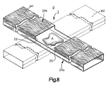
- the grid G is comprised of a notched muntin bar M1 and an unnotched muntin bar M2 interfitted at an intersection I.
- the notched muntin bar M1 is offset from the unnotched muntin bar M2. The offset occurs, because the unnotched muntin bar is thicker than the notch 22 in the notched muntin muntin bar M1.
- the muntin bars M1 and M2 are secured together by a suitable adhesive A in the illustrated embodiment.
- a section of the sidewalls 25 corresponding to the notch 22 is completely removed is to minimize the offset.
- the muntin bars M1, M2 are offset by the thickness of the material used to form the muntin bar and the thickness of the glue used to hold the muntin bars together.
- the muntin bar grid G depicted in Figure 8 can be constructed with the apparatus disclosed by U.S. Patent number 6,173,484 to McGlinchy et al.
- the '484 patent discloses a system for fabricating notched muntin bars from sheet material.
- the notched muntin bar M1 may be constructed using stock material S having first and second finishes 26, 28 in the apparatus disclosed by the '484 patent.
- the unnotched muntin bars may be constructed with the apparatus disclosed by the '484 patent by selectively disabling the first forming station (notching station).
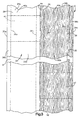
- Figure 3 shows a stock material S that is to be formed into a muntin bar M according to the invention.
- an outer surface 24 of the stock material S includes first and second finishes 26, 28.
- the first finish 26 is the finish presented to an observer from one side of the completed insulating glass unit 10 and the second finish is the finish presented to an observer from the opposite side of the insulating glass unit.
- the finish 26 is a woodgrain finish and the finish 28 is a single color painted finish.
- the stock material S is made from a thin elongated metal, for example, aluminum or steel that can be wound into an elongated strip as disclosed in pending U.S. patent application Serial No. 09/525,349, entitled “System for Fabricating Contour Muntin Bars From Sheet Material,” filed on March 15, 2000 and U.S. Patent No. 6,173,484 to McGlinchy.
- the first and second finishes 26, 28 are painted onto the outer surface 24 of the stock material S.
- the outer surface 24 is painted a desired color that corresponds with the second finish 28.
- the first finish 26 is achieved by applying a coating or covering layer 30 (Figure 3) to one side 32b of the outer surface 24 of the stock material S leaving a painted finish on the other side 32a uncovered.
- a coating or covering layer 30 Figure 3
- the details of one process for applying the coating 30 that may be used are described in detail in U.S. patent application Serial No. 09/781,630, entitled “Laminated Muntin Bar and Apparatus,” filed on February 12, 2001.
- the ribbon stock S is fed lengthwise through a muntin bar production line that includes a series of forming stations that form the ribbon stock into first and second sets of muntin bars.
- the illustrated muntin bars have a painted side 24a and a woodgrain finished side 24b.
- the first set of muntin bars each have one or more notches 22 in the woodgrain side 24b having the finish 26.
- the second set of muntin bars each have one or more notches 23 in the painted but unlaminated side 24a.
- Each of the muntin bars with a notch 22 in the first side 24a interfit with a muntin bar with a notch 23 in the second side 24b as depicted in Figure 2.
- the stock material S includes opposite edges 34a, 34b that, along with fold lines 36a, 36b define a pair of end panels 38a, 38b.
- the fold lines 36c, 36d define a central panel 42.
- a cutout 41, shown in phantom, extends inward from edge 34a of the stock material S illustrated in Figure 3 to a centerline 44.
- a second cutout 43 shown in phantom, extends inward from edge 34b to the centerline.
- the cutout 41 corresponds to a notch 23 in the painted but unlaminated side of one muntin bar and the cutout 43 corresponds to a notch 22 in the woodgrain side 24b of a second muntin bar.
- the break B illustrates that there is typically a distance between the cut-out 41 and the cutout 43.
- one half of the stock material S, extending from the centerline 44 to the edge 34b has the finish 26.
- the first and second finishes 26, 28 produce a different muntin bar appearance on opposite sides of the insulating glass unit 10.
- the stock S is punched to form muntin bars that will be positioned in a first orientation with notches 22 in the side 24b with the finish 26 (woodgrain in the illustrated embodiment) and muntin bars that will be positioned in a second orientation with notches 23 in the side 24a with the finish 28 (painted in the illustrated embodiment).
- Figure 6 illustrates an apparatus 46 for making sets of notched muntin bars M.
- the illustrated apparatus 46 includes an uncoiler 48 or support for the supply of ribbon stock S, a first accumulator 49, a notching device 50, a second accumulator 51, a roll forming machine 52, and a severing device 54.
- the notching device 50 receives the ribbon stock S from the ribbon stock uncoiler 48 by way of the first accumulator 49.
- the notching device 50 includes a punch 56 that is movable between a first position where the punch is engageable with a portion of the stock S having the finish 26 and a second position where the punch is engageable with a portion of the stock S having the finish 28.
- the punch 56 When the punch 56 is actuated it moves down and cuts through the ribbon stock S that intersects the punch to form cut-outs. After a cut-out is punched, the punch 56 is moved up and the stock S is advanced.
- the notching device 50 includes a pneumatic cylinder 58 that moves the punch 56 between the first and second positions.
- the pneumatic cylinder 58 is connected to a control 60 that causes the cylinder 58 to move the punch 56 to the first position when stock S that corresponds to a muntin bar that will be assembled in a muntin bar grid G in a vertical orientation is being punched.
- the control 60 causes the cylinder 58 to move the punch 56 to move to the second position 28, when stock S corresponds to a muntin bar that will be assembled in a horizontal orientation after being punched.
- the roll forming machine 52 receives the punched ribbon stock S from the notching device 50 by way of the second accumulator 51.
- the roll forming machine 52 bends the stock S to form hollow muntin bar stock having a side 24b with the finish 26 and a side 24a with the finish 28.
- the formed muntin bar stock has notches in the woodgrain side 24b corresponding to the cutouts 43 in the stock S and notches 23 in the painted side24a corresponding to the cutouts 41 in the stock S.
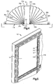
- FIG. 4 schematically indicates a progressive change in the shape of the stock strip S from a flat strip to a rectangular cross-section structure as the strip passes through multiple stages of the roll forming machine 52.
- the strip S is bent in the region of the fold lines 36a, 36b, 26c, 36d to form an enclosed structure having rectangular borders as seen from the end.
- this structure forms a muntin bar M that is interfitted with one or more other muntin bars to form a grid, such as the grid G of Figures 1 and 2.
- the severing device 54 severs the muntin bar stock S to form individual notched muntin bars M.
- a muntin bar conveyor 55 moves the muntin bars to the side after they are cut. Details of a severing device 54 and a muntin bar conveyor 55 that may be used, are disclosed in U.S. Patent No. 6,173,484 to McGlinchy.
- the muntin bar M includes an outer surface 24.
- the outer surface 24 includes an outwardly facing side 24a that would be visible to a person looking through the insulating glass unit 10 from one side of the unit and an outwardly facing side 24b that would be visible to a person looking through the insulating glass unit from the opposite side of the unit 10.
- an outer surface 24 of the strip S is painted or otherwise treated to have a first appearance and a portion of the outer surface 24, approximately half its width, is covered with the coating layer 30 having a second appearance.
- FIG. 4 Bending of the strip S as depicted in Figure 4 produces a two-tone muntin bar M that is, a muntin bar that has a first appearance on an outwardly facing surface 24a, and a second appearance on the outwardly facing surface 24b.
- the enlarged perspective view shown in Figure 5 shows an insulating glass unit 10 that includes such a muntin bar grid.
- the apparatus 46 is used to make individual muntin bars that can be assembled into a muntin bar grid G having two outwardly facing surfaces 24a, 24b.
- the supply of thin sheet stock S that has been treated to define first and second finishes 26, 28 on one side of the material.
- the thin sheet stock is selectively moved through the notching device 50.
- the control 60 determines that a provided length of sheet material corresponds to a muntin bar that will be assembled in a first orientation in a muntin bar grid G, such as a horizontal orientation, one or more sections of material having the finish 26 are removed from the material stock S that corresponds to the length of a muntin bar to form cutouts 43.
- the cylinder 58 is actuated to move the punch 56 to the side. Then one or more sections of material are removed from the portion of the strip having the finish 28 to form cutouts 41.
- the muntin bar stock S is passed through the rolling mill to form elongated tubular muntin bar stock S having a side 24a with the finish 28, and a side 24b with the second finish 26.
- the muntin bar stock S is severed at predetermined locations to form individual muntin bars.
- the muntin bars that will be assembled in the first orientation have notches 22 in the side 24b having the first finish 26.
- the muntin bars that will be assembled in the second orientation have notches 23 in the side 24a having the finish 28.
Landscapes
- Engineering & Computer Science (AREA)
- Mechanical Engineering (AREA)
- Civil Engineering (AREA)
- Structural Engineering (AREA)
- Bending Of Plates, Rods, And Pipes (AREA)
- Making Paper Articles (AREA)
- Metal Rolling (AREA)
- Automatic Assembly (AREA)
- Forging (AREA)
- Wire Processing (AREA)
- Press Drives And Press Lines (AREA)
Applications Claiming Priority (4)
| Application Number | Priority Date | Filing Date | Title |
|---|---|---|---|
| US09/781,630 US6687982B2 (en) | 2001-02-12 | 2001-02-12 | Laminated muntin bar apparatus |
| US781630 | 2001-02-12 | ||
| US975216 | 2001-10-11 | ||
| US09/975,216 US6708384B2 (en) | 1997-02-07 | 2001-10-11 | Notched muntin bars having two finishes |
Publications (2)
| Publication Number | Publication Date |
|---|---|
| EP1231352A2 true EP1231352A2 (fr) | 2002-08-14 |
| EP1231352A3 EP1231352A3 (fr) | 2003-04-02 |
Family
ID=27119891
Family Applications (1)
| Application Number | Title | Priority Date | Filing Date |
|---|---|---|---|
| EP02002983A Withdrawn EP1231352A3 (fr) | 2001-02-12 | 2002-02-11 | Procédé et dispositif de fabrication de profilés de croisillon entaillés pourvus de deux couches de finition |
Country Status (3)
| Country | Link |
|---|---|
| US (1) | US6708384B2 (fr) |
| EP (1) | EP1231352A3 (fr) |
| CA (1) | CA2369548C (fr) |
Families Citing this family (16)
| Publication number | Priority date | Publication date | Assignee | Title |
|---|---|---|---|---|
| US5980667A (en) * | 1997-10-24 | 1999-11-09 | Custom Glass Products Of Carolina, Inc. | Window, muntin and method |
| US7743570B2 (en) * | 1999-08-13 | 2010-06-29 | Edgetech I.G., Inc. | Method of fabricating muntin bars for simulated divided lite windows |
| US6622433B2 (en) * | 2000-09-15 | 2003-09-23 | David Blachley | Prefinished medium density fiberboard shutter |
| US7866033B2 (en) * | 2004-09-29 | 2011-01-11 | Ged Integrated Solutions, Inc. | Window component system including pusher for scrap removal |
| US7610681B2 (en) * | 2004-09-29 | 2009-11-03 | Ged Integrated Solutions, Inc. | Window component stock indexing |
| US7802365B2 (en) * | 2004-09-29 | 2010-09-28 | Ged Integrated Solutions, Inc. | Window component scrap reduction |
| US7445682B2 (en) | 2004-09-29 | 2008-11-04 | Ged Intergrated Solution, Inc. | Window component stock transferring |
| US20090139163A1 (en) * | 2007-12-04 | 2009-06-04 | Intigral, Inc. | Insulating glass unit |
| US20090139165A1 (en) * | 2007-12-04 | 2009-06-04 | Intigral, Inc. | Insulating glass unit |
| US20090139164A1 (en) * | 2007-12-04 | 2009-06-04 | Intigral, Inc. | Insulating glass unit |
| US7762466B2 (en) * | 2008-12-18 | 2010-07-27 | Symbol Technologies, Inc. | Two position zoom lens assembly for an imaging-based bar code reader |
| US8460489B2 (en) | 2010-08-13 | 2013-06-11 | Ged Integrated Solutions, Inc. | Flexible film application for decorative coatings |
| USD799719S1 (en) * | 2015-07-08 | 2017-10-10 | Newtonoid Technologies, L.L.C. | Insert for positioning between window panes |
| USD793580S1 (en) * | 2015-06-26 | 2017-08-01 | Newtonoid Technologies, L.L.C. | Insert for positioning against a window pane |
| US11739585B1 (en) | 2019-02-07 | 2023-08-29 | WWS Acquisition, LLC | Simulated steel fenestration system |
| USD927017S1 (en) | 2019-02-07 | 2021-08-03 | Wws Acquisition Llc | Muntin bar assembly |
Citations (4)
| Publication number | Priority date | Publication date | Assignee | Title |
|---|---|---|---|---|
| US525349A (en) | 1894-09-04 | Construction of ships | ||
| US781630A (en) | 1904-09-29 | 1905-02-07 | John C Brooks | Whip-socket. |
| US797031A (en) | 1904-01-20 | 1905-08-15 | John H Vivian | Combined door hanger and track. |
| US6173484B1 (en) | 1997-02-07 | 2001-01-16 | Glass Equipment Development, Inc. | System for fabricating muntin bars from sheet material |
Family Cites Families (20)
| Publication number | Priority date | Publication date | Assignee | Title |
|---|---|---|---|---|
| US3748814A (en) * | 1971-09-16 | 1973-07-31 | Capitol Prod Corp | Decorative metal grid system for windows |
| US4060950A (en) * | 1976-12-08 | 1977-12-06 | National Gypsum Company | Concealed clip for hollow strips |
| US4530195A (en) | 1980-04-03 | 1985-07-23 | Glass Equipment Development, Inc. | Spacer frame for an insulating glass panel and method of making the same |
| US5105591A (en) | 1980-04-03 | 1992-04-21 | Glass Equipment Development, Inc. | Spacer frame for an insulating glass panel and method of making the same |
| US4628582A (en) | 1981-12-04 | 1986-12-16 | Glass Equipment Development, Inc. | Method of making spacer frame for an insulating glass panel |
| US4455850A (en) * | 1980-12-31 | 1984-06-26 | E. I. Du Pont De Nemours And Company | Can manufacture |
| US4381726A (en) | 1981-11-17 | 1983-05-03 | A/S Phonix Tagpap Og Vejmaterialer | Apparatus for applying stripe material to a solid surface |
| US4546723A (en) | 1984-04-19 | 1985-10-15 | Glass Equipment Development, Inc. | Method and apparatus for applying sealant to insulating glass panel spacer frames |
| US4989384A (en) * | 1990-01-02 | 1991-02-05 | Rolscreen Company | Insulated window assembly with internal muntin bars |
| DE4030335C2 (de) | 1990-09-25 | 1998-05-20 | Lingemann Helmut Gmbh & Co | Sprossenhohlprofil für Isolierverglasungen sowie Verfahren zu seiner Herstellung |
| US5088307A (en) | 1990-12-20 | 1992-02-18 | Cole Richard D | Method of making muntin bars |
| US5313761A (en) | 1992-01-29 | 1994-05-24 | Glass Equipment Development, Inc. | Insulating glass unit |
| US5295292A (en) | 1992-08-13 | 1994-03-22 | Glass Equipment Development, Inc. | Method of making a spacer frame assembly |
| US5351459A (en) * | 1992-12-10 | 1994-10-04 | Kassl Robert A | Strength and decoration window grid system |
| US5574651A (en) | 1994-11-21 | 1996-11-12 | Mckeegan; John | Method and system for machining muntin sections and seating bars |
| US6687982B2 (en) * | 2001-02-12 | 2004-02-10 | Glass Equipment Development, Inc. | Laminated muntin bar apparatus |
| US6438819B1 (en) * | 1997-02-07 | 2002-08-27 | Glass Equipment Development, Inc. | System for fabricating contour muntin bars from sheet material |
| US6244012B1 (en) | 1999-01-20 | 2001-06-12 | Glass Equipment Development, Inc. | Muntin grid and joiner |
| WO2001012940A1 (fr) * | 1999-08-13 | 2001-02-22 | Edgetech I.G., Inc. | Procede de fabrication de meneaux pour fenetres vitrees a divisions simulees |
| GB2371591A (en) * | 2001-01-30 | 2002-07-31 | Michael Glover | Imitation stained glass window |
-
2001
- 2001-10-11 US US09/975,216 patent/US6708384B2/en not_active Expired - Lifetime
-
2002
- 2002-01-25 CA CA002369548A patent/CA2369548C/fr not_active Expired - Lifetime
- 2002-02-11 EP EP02002983A patent/EP1231352A3/fr not_active Withdrawn
Patent Citations (4)
| Publication number | Priority date | Publication date | Assignee | Title |
|---|---|---|---|---|
| US525349A (en) | 1894-09-04 | Construction of ships | ||
| US797031A (en) | 1904-01-20 | 1905-08-15 | John H Vivian | Combined door hanger and track. |
| US781630A (en) | 1904-09-29 | 1905-02-07 | John C Brooks | Whip-socket. |
| US6173484B1 (en) | 1997-02-07 | 2001-01-16 | Glass Equipment Development, Inc. | System for fabricating muntin bars from sheet material |
Also Published As
| Publication number | Publication date |
|---|---|
| EP1231352A3 (fr) | 2003-04-02 |
| US20020056183A1 (en) | 2002-05-16 |
| CA2369548C (fr) | 2006-04-04 |
| US6708384B2 (en) | 2004-03-23 |
| CA2369548A1 (fr) | 2002-08-12 |
Similar Documents
| Publication | Publication Date | Title |
|---|---|---|
| US6708384B2 (en) | Notched muntin bars having two finishes | |
| US6889416B2 (en) | Process for making laminating preformed muntin bars | |
| CA2579978C (fr) | Patte d'attache a petit bois et ensemble de petit bois | |
| US6684474B2 (en) | Method of fabricating muntin bars for simulated divided lite windows | |
| CA2381738C (fr) | Procede de fabrication de meneaux pour fenetres vitrees a divisions simulees | |
| KR101470884B1 (ko) | 프로파일 성형 방법 및 생산 라인 | |
| US4876837A (en) | Corner bead structure | |
| US3911554A (en) | Method of bending a laminated building panel and a corner produced thereby | |
| US6651304B2 (en) | Method for fabricating contour muntin bars from sheet material | |
| CA2254020C (fr) | Couvre-joint de construction d'un seul tenant a sections multiples | |
| US6705150B1 (en) | Method of making a raised panel door section for a garage door | |
| WO2008030028A1 (fr) | Appareil pour la fabrication de châssis de fenêtre et de porte | |
| DE102009052572A1 (de) | Abstandhalterrohr für eine Isolierverglasung, sowie Vorrichtung und Verfahren zur Herstellung des Abstandhalterrohrs und Isolierverglasung mit einem aus derartigen Abstandhalterrohren zusammengesetzten Abstandhalterrahmen | |
| US4669233A (en) | Curved window assembly and method of formation | |
| KR100348534B1 (ko) | 건축용 복합판넬 | |
| US4730380A (en) | Method of forming a curved window assembly | |
| WO2001042583A1 (fr) | Procede de fabrication de barres profilees metalliques servant de structures de support pour des panneaux, en particulier en platre et barre profilee fabriquee au moyen de ce procede | |
| JPH0788996A (ja) | 構造用バ−材及びその生産方法 | |
| CA2310993C (fr) | Systeme de fabrication de meneaux courbes a partir de tole | |
| KR20250136020A (ko) | 건물의 롱 코너 커버 및 이를 제조하는 방법 및 장치 | |
| US5088308A (en) | Method of making spacer bars |
Legal Events
| Date | Code | Title | Description |
|---|---|---|---|
| PUAI | Public reference made under article 153(3) epc to a published international application that has entered the european phase |
Free format text: ORIGINAL CODE: 0009012 |
|
| AK | Designated contracting states |
Kind code of ref document: A2 Designated state(s): AT BE CH CY DE DK ES FI FR GB GR IE IT LI LU MC NL PT SE TR |
|
| AX | Request for extension of the european patent |
Free format text: AL;LT;LV;MK;RO;SI |
|
| PUAL | Search report despatched |
Free format text: ORIGINAL CODE: 0009013 |
|
| AK | Designated contracting states |
Kind code of ref document: A3 Designated state(s): AT BE CH CY DE DK ES FI FR GB GR IE IT LI LU MC NL PT SE TR Designated state(s): AT BE CH CY DE DK ES FI FR GB GR IE IT LI LU MC NL PT SE TR |
|
| AX | Request for extension of the european patent |
Extension state: AL LT LV MK RO SI |
|
| 17P | Request for examination filed |
Effective date: 20031002 |
|
| AKX | Designation fees paid |
Designated state(s): AT BE CH CY DE DK ES FI FR GB GR IE IT LI LU MC NL PT SE TR |
|
| STAA | Information on the status of an ep patent application or granted ep patent |
Free format text: STATUS: THE APPLICATION IS DEEMED TO BE WITHDRAWN |
|
| 18D | Application deemed to be withdrawn |
Effective date: 20040831 |