EP1231372A2 - Verfahren zur Schätzung der Zylinderfüllung in einer Brennkraftmaschine - Google Patents
Verfahren zur Schätzung der Zylinderfüllung in einer Brennkraftmaschine Download PDFInfo
- Publication number
- EP1231372A2 EP1231372A2 EP02003065A EP02003065A EP1231372A2 EP 1231372 A2 EP1231372 A2 EP 1231372A2 EP 02003065 A EP02003065 A EP 02003065A EP 02003065 A EP02003065 A EP 02003065A EP 1231372 A2 EP1231372 A2 EP 1231372A2
- Authority
- EP
- European Patent Office
- Prior art keywords
- cylinder
- vvt
- induction
- thr
- engine
- Prior art date
- Legal status (The legal status is an assumption and is not a legal conclusion. Google has not performed a legal analysis and makes no representation as to the accuracy of the status listed.)
- Granted
Links
Images
Classifications
-
- F—MECHANICAL ENGINEERING; LIGHTING; HEATING; WEAPONS; BLASTING
- F02—COMBUSTION ENGINES; HOT-GAS OR COMBUSTION-PRODUCT ENGINE PLANTS
- F02D—CONTROLLING COMBUSTION ENGINES
- F02D13/00—Controlling the engine output power by varying inlet or exhaust valve operating characteristics, e.g. timing
- F02D13/02—Controlling the engine output power by varying inlet or exhaust valve operating characteristics, e.g. timing during engine operation
- F02D13/0203—Variable control of intake and exhaust valves
- F02D13/0215—Variable control of intake and exhaust valves changing the valve timing only
-
- F—MECHANICAL ENGINEERING; LIGHTING; HEATING; WEAPONS; BLASTING
- F02—COMBUSTION ENGINES; HOT-GAS OR COMBUSTION-PRODUCT ENGINE PLANTS
- F02D—CONTROLLING COMBUSTION ENGINES
- F02D41/00—Electrical control of supply of combustible mixture or its constituents
- F02D41/0002—Controlling intake air
-
- F—MECHANICAL ENGINEERING; LIGHTING; HEATING; WEAPONS; BLASTING
- F02—COMBUSTION ENGINES; HOT-GAS OR COMBUSTION-PRODUCT ENGINE PLANTS
- F02D—CONTROLLING COMBUSTION ENGINES
- F02D41/00—Electrical control of supply of combustible mixture or its constituents
- F02D41/0002—Controlling intake air
- F02D2041/001—Controlling intake air for engines with variable valve actuation
-
- F—MECHANICAL ENGINEERING; LIGHTING; HEATING; WEAPONS; BLASTING
- F02—COMBUSTION ENGINES; HOT-GAS OR COMBUSTION-PRODUCT ENGINE PLANTS
- F02D—CONTROLLING COMBUSTION ENGINES
- F02D2200/00—Input parameters for engine control
- F02D2200/02—Input parameters for engine control the parameters being related to the engine
- F02D2200/04—Engine intake system parameters
- F02D2200/0402—Engine intake system parameters the parameter being determined by using a model of the engine intake or its components
-
- F—MECHANICAL ENGINEERING; LIGHTING; HEATING; WEAPONS; BLASTING
- F02—COMBUSTION ENGINES; HOT-GAS OR COMBUSTION-PRODUCT ENGINE PLANTS
- F02D—CONTROLLING COMBUSTION ENGINES
- F02D2200/00—Input parameters for engine control
- F02D2200/02—Input parameters for engine control the parameters being related to the engine
- F02D2200/04—Engine intake system parameters
- F02D2200/0406—Intake manifold pressure
-
- F—MECHANICAL ENGINEERING; LIGHTING; HEATING; WEAPONS; BLASTING
- F02—COMBUSTION ENGINES; HOT-GAS OR COMBUSTION-PRODUCT ENGINE PLANTS
- F02D—CONTROLLING COMBUSTION ENGINES
- F02D2200/00—Input parameters for engine control
- F02D2200/02—Input parameters for engine control the parameters being related to the engine
- F02D2200/04—Engine intake system parameters
- F02D2200/0411—Volumetric efficiency
-
- Y—GENERAL TAGGING OF NEW TECHNOLOGICAL DEVELOPMENTS; GENERAL TAGGING OF CROSS-SECTIONAL TECHNOLOGIES SPANNING OVER SEVERAL SECTIONS OF THE IPC; TECHNICAL SUBJECTS COVERED BY FORMER USPC CROSS-REFERENCE ART COLLECTIONS [XRACs] AND DIGESTS
- Y02—TECHNOLOGIES OR APPLICATIONS FOR MITIGATION OR ADAPTATION AGAINST CLIMATE CHANGE
- Y02T—CLIMATE CHANGE MITIGATION TECHNOLOGIES RELATED TO TRANSPORTATION
- Y02T10/00—Road transport of goods or passengers
- Y02T10/10—Internal combustion engine [ICE] based vehicles
- Y02T10/12—Improving ICE efficiencies
-
- Y—GENERAL TAGGING OF NEW TECHNOLOGICAL DEVELOPMENTS; GENERAL TAGGING OF CROSS-SECTIONAL TECHNOLOGIES SPANNING OVER SEVERAL SECTIONS OF THE IPC; TECHNICAL SUBJECTS COVERED BY FORMER USPC CROSS-REFERENCE ART COLLECTIONS [XRACs] AND DIGESTS
- Y02—TECHNOLOGIES OR APPLICATIONS FOR MITIGATION OR ADAPTATION AGAINST CLIMATE CHANGE
- Y02T—CLIMATE CHANGE MITIGATION TECHNOLOGIES RELATED TO TRANSPORTATION
- Y02T10/00—Road transport of goods or passengers
- Y02T10/10—Internal combustion engine [ICE] based vehicles
- Y02T10/40—Engine management systems
Definitions
- the present invention concerns a method for estimating the filling of a cylinder in an internal combustion engine.
- This invention can be advantageously applied in internal combustion engines with variable cam stroke, to which the following description will explicitly refer without losing out in general terms.
- the known internal combustion engines are provided with a control unit which, at every engine cycle, determines the adjustment values for optimising combustion in the individual cylinders in order to obtain maximum efficiency possible in all operating conditions.
- the control unit requires certain information concerning the current operating status of the engine; among this information, estimation of the filling of each cylinder is important, i.e. estimation of the mass of fresh air (combustion agent) sucked in by each cylinder during the induction phase.
- Estimation of the filling of each cylinder is particularly complicated in internal combustion engines with variable cam stroke because modification of the induction and/or exhaust phase affects the cylinder filling capacity, thus modifying the "acoustic" characteristics of the induction and/or exhaust subsystems.
- the actual position of the stroke variator in induction/exhaust with respect to the rest position determines both the different induction capacity of the cylinders and the amount of exhaust gas trapped inside them.
- an air flow rate meter is normally used, fitted upstream of the cylinder inlet valve; the use of air flow rate meters is expensive, however, due to the high cost of the devices themselves.
- Another known solution for estimating the filling of each cylinder is to parameterise reconstruction of the cylinder load in two-dimensional planes according to assigned induction/exhaust timing values; by linear interpolation between two adjacent two-dimensional planes, the cylinder filling is determined for all permitted induction/exhaust timing values.
- this solution is fairly expensive as it involves the use of a large-capacity and therefore costly memory in the control unit to store all the necessary two-dimensional planes; furthermore, said solution requires fairly lengthy engine test bench set-up times.
- the aim of the present invention is to provide a method for estimating the filling of a cylinder in an internal combustion engine which has none of the disadvantages described and, in particular, is easy and inexpensive to implement.
- a method for estimating the filling of a cylinder in an internal combustion engine according to claim 1.
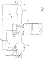
- ref. no. 1 indicates, overall, an internal combustion engine provided with four cylinders 2 (of which only one is illustrated in figure 1), each of which is connected to an inlet manifold 3 via at least one respective inlet valve 4 and to an exhaust manifold 5 via at least one respective exhaust valve 6.
- the inlet manifold 3 receives fresh air (i.e. air from the outside containing approximately 20% oxygen) via a throttle valve 7 that can be adjusted from a closed to a maximum opening position.
- the exhaust manifold 5 leads to an exhaust pipe 8 which terminates in a silencer (known and not illustrated) for emission into the atmosphere of the gases produced by combustion.
- the inlet valve 4 and the exhaust valve 6 are controlled by a cam control device 9, which is of known type and provided with mechanical cam stroke variation system 10.
- the fuel for example petrol, diesel, methane, LPG .
- the injector 11 of substantially known type; according to a different embodiment not illustrated, the fuel is injected directly into each cylinder 2 by means of a respective injector.
- the engine 1 furthermore comprises a control unit 12 which, in particular, controls at each cycle the throttle valve 7 and the injector 11 for filling the cylinders 2 with a mixture of combustion agent (fresh air) and fuel in a proportion determined according to the operating conditions of the engine 1 and according to the commands received from the driver.
- the control unit 12 is connected to a lambda probe 13 which is fitted in the exhaust pipe 8 and is designed to determine in a known way the amount of oxygen present in the gases contained in said exhaust pipe 8.
- the control unit 12 is provided with an estimation device 14 which is designed to provide said control unit 12 with an estimation, moment by moment, of the mass m a of fresh air (i.e. combustion agent) sucked in by each cylinder 2 during induction and, therefore, the respective induction efficiency ⁇ asp . defined by the ratio (summarised in equation [1]) between the mass m a of fresh air sucked in by the cylinder 2 and the mass m apot of fresh air that can be potentially sucked in by the cylinder 2 in the ambient reference conditions, i.e. atmospheric pressure 101300 Pa and temperature 298°K.
- the control unit 12 is connected to a sensor 15 of known type which is fitted inside the inlet manifold 3 and is designed to measure the pressure p a and temperature t a of the gas in the inlet manifold 3.
- the control unit 12 is furthermore connected to sensors (not illustrated) of known type, which are designed to measure the temperature t H2O of the cooling liquid of the engine 1, the atmospheric pressure p atm and the rotation speed n of the engine 1.
- the presence of the cam stroke variation system 10 affects to a fairly considerable extent the mass m a of fresh air (i.e. combustion agent) sucked in by each cylinder 2, as the variation of the moment when the inlet and exhaust valves 4 and 6 begin to open modifies both the induction capacity of cylinder 2 and the amount of residual burnt gas inside said cylinder 2.
- the dynamic effects of the filling of each cylinder 2 can be classified into two types: the dynamic effects due to the fluid dynamic pressure losses present on the different components making up the induction circuit, and the dynamic effects depending on the acoustics of the induction circuit.
- the dynamic effects depending on the acoustics of the induction circuit consist mainly of:
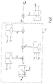
- the estimation device 14 estimates a theoretical induction efficiency ⁇ thr which each cylinder 2 would have if it operated with the optimal induction/exhaust timing value VVT, i.e. with the induction/exhaust timing value VVT that permits maximisation of the mass m a of fresh air (i.e. combustion agent) that can be sucked in by said cylinder 2.
- the estimation device 14 derates the theoretical induction efficiency ⁇ thr by multiplying it by a correction factor K VVT which is between 0 and 1 (in real applications it is between 0.6 and 1) and dependent on the induction/exhaust timing value VVT actually used by the engine 1.
- K VVT A(n)*(VVT-VVTopt(n)) 2 +B(n)*(VVT-VVTopt(n))+1 in which:
- K VVT the relation between the correction factor K VVT and the timing value VVT is represented by a series of parabolas, each of which is distinguished by a set speed value n of the engine 1.
- the estimation device 14 uses an estimation component 16 which is substantially able to estimate the induction efficiency in an internal combustion engine with constant timing (i.e. without the cam stroke variation system 10) according to the pressure p a and temperature t a of the gas in the inlet manifold 3, the temperature t H2O of the cooling liquid of the engine 1, the atmospheric pressure p atm and the rotation speed n of the engine 1.
- the engine 1 has constant timing, i.e. it is without the cam stroke variation system 10, and operates with an optimal VVT value.
- the induction efficiency ⁇ thr is defined by the ratio between the mass m a of fresh air (i.e. combustion agent) sucked in by a cylinder 2 and the mass m apot of fresh air that can be potentially sucked in by cylinder 2 in the ambient reference conditions, i.e. atmospheric pressure 101300 Pa and temperature 298°K.
- the mass m a of fresh air sucked in by a cylinder 2 is assumed that the induction cycle of cylinder 2 is an ideal cycle, that the gaseous fluid sucked in is a perfect gas, that the temperature of the gaseous fluid sucked in is constant during the entire induction cycle and that the cylinder 2 is an isolated system.
- the mass m a of fresh air sucked in by a cylinder is given by the difference between the mass m asp of gas present in the cylinder 2 at the end, of the induction phase and the mass m scar of gas present in the cylinder 2 at the beginning of the induction phase, i.e. at the end of the exhaust phase.
- equation [11] which provides the theoretical mass of gas trapped in the cylinder at the end of the induction phase:
Landscapes
- Engineering & Computer Science (AREA)
- Chemical & Material Sciences (AREA)
- Combustion & Propulsion (AREA)
- Mechanical Engineering (AREA)
- General Engineering & Computer Science (AREA)
- Output Control And Ontrol Of Special Type Engine (AREA)
- Combined Controls Of Internal Combustion Engines (AREA)
- Valve-Gear Or Valve Arrangements (AREA)
Applications Claiming Priority (2)
| Application Number | Priority Date | Filing Date | Title |
|---|---|---|---|
| IT2001BO000076A ITBO20010076A1 (it) | 2001-02-13 | 2001-02-13 | Metodo per la stima del reperimento di un cilindro in un motore a combustione interna |
| ITBO010076 | 2001-02-13 |
Publications (3)
| Publication Number | Publication Date |
|---|---|
| EP1231372A2 true EP1231372A2 (de) | 2002-08-14 |
| EP1231372A3 EP1231372A3 (de) | 2003-05-02 |
| EP1231372B1 EP1231372B1 (de) | 2016-11-02 |
Family
ID=11439089
Family Applications (1)
| Application Number | Title | Priority Date | Filing Date |
|---|---|---|---|
| EP02003065.6A Expired - Lifetime EP1231372B1 (de) | 2001-02-13 | 2002-02-12 | Verfahren zur Schätzung der Zylinderfüllung in einer Brennkraftmaschine |
Country Status (4)
| Country | Link |
|---|---|
| US (1) | US6728624B2 (de) |
| EP (1) | EP1231372B1 (de) |
| BR (1) | BR0200426B1 (de) |
| IT (1) | ITBO20010076A1 (de) |
Cited By (5)
| Publication number | Priority date | Publication date | Assignee | Title |
|---|---|---|---|---|
| EP1408220A1 (de) * | 2002-09-20 | 2004-04-14 | Caterpillar Inc. | System und Verfahren zur Steuerung einer Brennkraftmaschine |
| EP1353055A3 (de) * | 2002-04-10 | 2004-08-18 | Robert Bosch Gmbh | Verfahren zum Betreiben einer Brennkraftmaschine, Brennkraftmaschine und Steuerelement |
| WO2006000474A1 (de) * | 2004-06-24 | 2006-01-05 | Siemens Aktiengesellschaft | Verfahren zur bestimmung der luftmasse in einem zylinder |
| EP2264300A3 (de) * | 2002-12-17 | 2012-07-11 | Toyota Jidosha Kabushiki Kaisha | System zur Berechnung des Abgasrückführstroms in den Zylinder und in die Saugleitung einer Brennkraftmaschine |
| US10774757B2 (en) | 2016-03-18 | 2020-09-15 | Volkswagen Aktiengesellschaft | Method and controller for determining the quantity of filling components in a cylinder of an internal combustion engine |
Families Citing this family (5)
| Publication number | Priority date | Publication date | Assignee | Title |
|---|---|---|---|---|
| DE60320594T2 (de) * | 2003-08-29 | 2009-06-10 | Penn Elastic Gmbh | Stoffrohling, dessen herstellung sowie damit hergestelltes kleidungsstück |
| FR2959775B1 (fr) * | 2010-05-07 | 2012-05-25 | Peugeot Citroen Automobiles Sa | Procede d'estimation d'une quantite d'air frais, support d'enregistrement et estimateur pour ce procede, vehicule equipe de cet estimateur |
| RU2542771C2 (ru) * | 2013-02-21 | 2015-02-27 | Федеральное государственное бюджетное образовательное учреждение высшего профессионального образования "Государственный морской университет имени адмирала Ф.Ф. Ушакова" | Способ контроля расхода воздуха судовой дизельной установки при эксплуатации судна |
| CN106704004B (zh) * | 2015-11-13 | 2020-06-16 | 日立汽车系统(中国)有限公司 | 内燃机以及内燃机的控制方法 |
| DE102021006374A1 (de) * | 2021-12-28 | 2023-06-29 | 2G Energy AG | Verfahren zum Betrieb einer Brennkraftmaschine mit Gasgemischen hoher Flammengeschwindigkeit und niedriger Zündenergie sowie entsprechende Brennkraftmaschine |
Citations (1)
| Publication number | Priority date | Publication date | Assignee | Title |
|---|---|---|---|---|
| US5714683A (en) | 1996-12-02 | 1998-02-03 | General Motors Corporation | Internal combustion engine intake port flow determination |
Family Cites Families (7)
| Publication number | Priority date | Publication date | Assignee | Title |
|---|---|---|---|---|
| US4633403A (en) * | 1984-04-05 | 1986-12-30 | Chrysler Motors Corporation | Engine valve timing |
| DE4111153A1 (de) * | 1991-04-06 | 1992-10-08 | Fev Motorentech Gmbh & Co Kg | Einlasssteuerung fuer verbrennungskraftmaschinen |
| FR2712350B1 (fr) * | 1993-11-10 | 1996-02-09 | Siemens Automotive Sa | Procédé et dispositif d'optimisation ou remplissage en air d'un cylindre de moteur à combustion interne. |
| US5520153A (en) * | 1995-04-28 | 1996-05-28 | Saturn Corporation | Internal combustion engine control |
| DE19906707A1 (de) * | 1999-02-18 | 2000-08-24 | Bayerische Motoren Werke Ag | Verfahren zur Bestimmung der Zylinderbefüllung bei ungedrosselten Verbrennungsmotoren |
| US6393903B1 (en) * | 1999-12-10 | 2002-05-28 | Delphi Technologies, Inc. | Volumetric efficiency compensation for dual independent continuously variable cam phasing |
| US6371066B1 (en) * | 2000-12-15 | 2002-04-16 | Ford Global Technologies, Inc. | Torque based cam timing control method and system |
-
2001
- 2001-02-13 IT IT2001BO000076A patent/ITBO20010076A1/it unknown
-
2002
- 2002-02-12 EP EP02003065.6A patent/EP1231372B1/de not_active Expired - Lifetime
- 2002-02-13 US US10/073,257 patent/US6728624B2/en not_active Expired - Lifetime
- 2002-02-13 BR BRPI0200426-7A patent/BR0200426B1/pt not_active IP Right Cessation
Patent Citations (1)
| Publication number | Priority date | Publication date | Assignee | Title |
|---|---|---|---|---|
| US5714683A (en) | 1996-12-02 | 1998-02-03 | General Motors Corporation | Internal combustion engine intake port flow determination |
Cited By (7)
| Publication number | Priority date | Publication date | Assignee | Title |
|---|---|---|---|---|
| EP1353055A3 (de) * | 2002-04-10 | 2004-08-18 | Robert Bosch Gmbh | Verfahren zum Betreiben einer Brennkraftmaschine, Brennkraftmaschine und Steuerelement |
| EP1408220A1 (de) * | 2002-09-20 | 2004-04-14 | Caterpillar Inc. | System und Verfahren zur Steuerung einer Brennkraftmaschine |
| US6799552B2 (en) | 2002-09-20 | 2004-10-05 | Caterpillar Inc | System and method for controlling engine operation |
| EP2264300A3 (de) * | 2002-12-17 | 2012-07-11 | Toyota Jidosha Kabushiki Kaisha | System zur Berechnung des Abgasrückführstroms in den Zylinder und in die Saugleitung einer Brennkraftmaschine |
| WO2006000474A1 (de) * | 2004-06-24 | 2006-01-05 | Siemens Aktiengesellschaft | Verfahren zur bestimmung der luftmasse in einem zylinder |
| US7357127B2 (en) | 2004-06-24 | 2008-04-15 | Siemens Aktiengesellschaft | Method for determining the air mass in a cylinder |
| US10774757B2 (en) | 2016-03-18 | 2020-09-15 | Volkswagen Aktiengesellschaft | Method and controller for determining the quantity of filling components in a cylinder of an internal combustion engine |
Also Published As
| Publication number | Publication date |
|---|---|
| US20020148285A1 (en) | 2002-10-17 |
| US6728624B2 (en) | 2004-04-27 |
| BR0200426B1 (pt) | 2014-07-29 |
| EP1231372B1 (de) | 2016-11-02 |
| BR0200426A (pt) | 2002-10-08 |
| ITBO20010076A1 (it) | 2002-08-13 |
| ITBO20010076A0 (it) | 2001-02-13 |
| EP1231372A3 (de) | 2003-05-02 |
Similar Documents
| Publication | Publication Date | Title |
|---|---|---|
| US7367318B2 (en) | Control system and control method of internal combustion engine | |
| Moskwa et al. | Modeling and validation of automotive engines for control algorithm development | |
| JP7398246B2 (ja) | 内燃エンジンのそれぞれのシリンダーの中に捕捉される空気の質量を特定する方法 | |
| US6681729B2 (en) | Method and device for controlling a gas fill of cylinders of an internal combustion engine | |
| US20040093148A1 (en) | Method and system for estimating cylinder charge for internal combustion engines having variable valve timing | |
| US6810855B2 (en) | 4-Stroke engine control device and control method | |
| US6728624B2 (en) | Method for estimating the filling of a cylinder in an internal combustion engine | |
| US7347183B2 (en) | Control apparatus and control method for engine | |
| EP1510677A2 (de) | Steuervorrichtung für eine Brennkraftmaschine | |
| EP3707361B1 (de) | Messung, modellierung und schätzung des scavenging-luftstroms in einem verbrennungsmotor | |
| EP1662118A1 (de) | Vorrichtung und verfahren zur steuerung der saugluftmenge in einem verbrennungsmotor | |
| Khameneian et al. | Model-based dynamic in-cylinder air charge, residual gas and temperature estimation for a GDI spark ignition engine using cylinder, intake and exhaust pressures | |
| US7137381B1 (en) | Indirect variable valve actuation for an internal combustion engine | |
| RU2525862C2 (ru) | Способ и устройство для оценки массы свежего воздуха в камере сгорания, способ оценки полного заполнения, блок записи для этих способов и автомобиль, оборудованный устройством для оценки | |
| Wang et al. | Control-oriented model-based burn duration and ignition timing prediction with recursive-least-square adaptation for closed-loop combustion phasing control of a spark ignition engine | |
| JP2009524770A (ja) | エンジンガス組成物の同定方法 | |
| Colin et al. | In-cylinder mass estimation using cylinder pressure | |
| Koehler et al. | A model for a fast prediction of the in-cylinder residual gas mass | |
| Karagiorgis et al. | Dynamic modeling of combustion and gas exchange processes for controlled auto-ignition engines | |
| JP2002227684A (ja) | エンジンの燃料噴射制御装置 | |
| Meyer | Engine modeling of an internal combustion engine with twin independent cam phasing | |
| Thomasson et al. | Cylinder pressure based cylinder charge estimation in diesel engines with dual independent variable valve timing | |
| JP7124516B2 (ja) | 内燃機関の燃焼制御装置 | |
| EP1460253B1 (de) | Verfahren und Vorrichtung zur Regelung der Einlassventil-Steuerzeiten einer Brennkraftmaschine | |
| Wenig et al. | Fundamentals of pressure trace analysis for gasoline engines with Homogeneous Charge Compression Ignition |
Legal Events
| Date | Code | Title | Description |
|---|---|---|---|
| PUAI | Public reference made under article 153(3) epc to a published international application that has entered the european phase |
Free format text: ORIGINAL CODE: 0009012 |
|
| AK | Designated contracting states |
Kind code of ref document: A2 Designated state(s): AT BE CH CY DE DK ES FI FR GB GR IE IT LI LU MC NL PT SE TR |
|
| AX | Request for extension of the european patent |
Free format text: AL;LT;LV;MK;RO;SI |
|
| PUAL | Search report despatched |
Free format text: ORIGINAL CODE: 0009013 |
|
| AK | Designated contracting states |
Designated state(s): AT BE CH CY DE DK ES FI FR GB GR IE IT LI LU MC NL PT SE TR |
|
| AX | Request for extension of the european patent |
Extension state: AL LT LV MK RO SI |
|
| 17P | Request for examination filed |
Effective date: 20031031 |
|
| AKX | Designation fees paid |
Designated state(s): DE ES FR GB SE |
|
| 17Q | First examination report despatched |
Effective date: 20091110 |
|
| GRAP | Despatch of communication of intention to grant a patent |
Free format text: ORIGINAL CODE: EPIDOSNIGR1 |
|
| INTG | Intention to grant announced |
Effective date: 20160512 |
|
| RAP1 | Party data changed (applicant data changed or rights of an application transferred) |
Owner name: MAGNETI MARELLI S.P.A. |
|
| GRAS | Grant fee paid |
Free format text: ORIGINAL CODE: EPIDOSNIGR3 |
|
| GRAA | (expected) grant |
Free format text: ORIGINAL CODE: 0009210 |
|
| AK | Designated contracting states |
Kind code of ref document: B1 Designated state(s): DE ES FR GB SE |
|
| REG | Reference to a national code |
Ref country code: GB Ref legal event code: FG4D |
|
| REG | Reference to a national code |
Ref country code: DE Ref legal event code: R096 Ref document number: 60248445 Country of ref document: DE |
|
| REG | Reference to a national code |
Ref country code: FR Ref legal event code: PLFP Year of fee payment: 16 |
|
| PG25 | Lapsed in a contracting state [announced via postgrant information from national office to epo] |
Ref country code: SE Free format text: LAPSE BECAUSE OF FAILURE TO SUBMIT A TRANSLATION OF THE DESCRIPTION OR TO PAY THE FEE WITHIN THE PRESCRIBED TIME-LIMIT Effective date: 20161102 |
|
| PG25 | Lapsed in a contracting state [announced via postgrant information from national office to epo] |
Ref country code: ES Free format text: LAPSE BECAUSE OF FAILURE TO SUBMIT A TRANSLATION OF THE DESCRIPTION OR TO PAY THE FEE WITHIN THE PRESCRIBED TIME-LIMIT Effective date: 20161102 |
|
| REG | Reference to a national code |
Ref country code: DE Ref legal event code: R097 Ref document number: 60248445 Country of ref document: DE |
|
| PLBE | No opposition filed within time limit |
Free format text: ORIGINAL CODE: 0009261 |
|
| STAA | Information on the status of an ep patent application or granted ep patent |
Free format text: STATUS: NO OPPOSITION FILED WITHIN TIME LIMIT |
|
| 26N | No opposition filed |
Effective date: 20170803 |
|
| GBPC | Gb: european patent ceased through non-payment of renewal fee |
Effective date: 20170212 |
|
| REG | Reference to a national code |
Ref country code: FR Ref legal event code: PLFP Year of fee payment: 17 |
|
| PG25 | Lapsed in a contracting state [announced via postgrant information from national office to epo] |
Ref country code: GB Free format text: LAPSE BECAUSE OF NON-PAYMENT OF DUE FEES Effective date: 20170212 |
|
| PGFP | Annual fee paid to national office [announced via postgrant information from national office to epo] |
Ref country code: DE Payment date: 20200121 Year of fee payment: 19 |
|
| PGFP | Annual fee paid to national office [announced via postgrant information from national office to epo] |
Ref country code: FR Payment date: 20200122 Year of fee payment: 19 |
|
| REG | Reference to a national code |
Ref country code: DE Ref legal event code: R119 Ref document number: 60248445 Country of ref document: DE |
|
| PG25 | Lapsed in a contracting state [announced via postgrant information from national office to epo] |
Ref country code: FR Free format text: LAPSE BECAUSE OF NON-PAYMENT OF DUE FEES Effective date: 20210228 Ref country code: DE Free format text: LAPSE BECAUSE OF NON-PAYMENT OF DUE FEES Effective date: 20210901 |