EP1231385A1 - Dispositif d'alimentation en huile hydraulique, huile lubrifiante ou analogues - Google Patents
Dispositif d'alimentation en huile hydraulique, huile lubrifiante ou analogues Download PDFInfo
- Publication number
- EP1231385A1 EP1231385A1 EP02002243A EP02002243A EP1231385A1 EP 1231385 A1 EP1231385 A1 EP 1231385A1 EP 02002243 A EP02002243 A EP 02002243A EP 02002243 A EP02002243 A EP 02002243A EP 1231385 A1 EP1231385 A1 EP 1231385A1
- Authority
- EP
- European Patent Office
- Prior art keywords
- valve block
- pump
- hydraulic
- plastic
- hydraulic pump
- Prior art date
- Legal status (The legal status is an assumption and is not a legal conclusion. Google has not performed a legal analysis and makes no representation as to the accuracy of the status listed.)
- Granted
Links
- 239000010720 hydraulic oil Substances 0.000 title claims description 5
- 239000010687 lubricating oil Substances 0.000 title claims description 4
- 239000004033 plastic Substances 0.000 claims description 15
- 238000002347 injection Methods 0.000 claims description 3
- 239000007924 injection Substances 0.000 claims description 3
- 238000004873 anchoring Methods 0.000 claims description 2
- 239000000126 substance Substances 0.000 abstract 1
- XAGFODPZIPBFFR-UHFFFAOYSA-N aluminium Chemical compound [Al] XAGFODPZIPBFFR-UHFFFAOYSA-N 0.000 description 4
- 229910052782 aluminium Inorganic materials 0.000 description 4
- 239000012530 fluid Substances 0.000 description 3
- 238000004519 manufacturing process Methods 0.000 description 3
- 230000002787 reinforcement Effects 0.000 description 2
- 239000007769 metal material Substances 0.000 description 1
- 239000002991 molded plastic Substances 0.000 description 1
- 238000001556 precipitation Methods 0.000 description 1
- 230000001737 promoting effect Effects 0.000 description 1
- 238000007789 sealing Methods 0.000 description 1
- 239000000243 solution Substances 0.000 description 1
Images
Classifications
-
- F—MECHANICAL ENGINEERING; LIGHTING; HEATING; WEAPONS; BLASTING
- F04—POSITIVE - DISPLACEMENT MACHINES FOR LIQUIDS; PUMPS FOR LIQUIDS OR ELASTIC FLUIDS
- F04C—ROTARY-PISTON, OR OSCILLATING-PISTON, POSITIVE-DISPLACEMENT MACHINES FOR LIQUIDS; ROTARY-PISTON, OR OSCILLATING-PISTON, POSITIVE-DISPLACEMENT PUMPS
- F04C11/00—Combinations of two or more machines or pumps, each being of rotary-piston or oscillating-piston type; Pumping installations
-
- F—MECHANICAL ENGINEERING; LIGHTING; HEATING; WEAPONS; BLASTING
- F04—POSITIVE - DISPLACEMENT MACHINES FOR LIQUIDS; PUMPS FOR LIQUIDS OR ELASTIC FLUIDS
- F04B—POSITIVE-DISPLACEMENT MACHINES FOR LIQUIDS; PUMPS
- F04B23/00—Pumping installations or systems
- F04B23/02—Pumping installations or systems having reservoirs
- F04B23/021—Pumping installations or systems having reservoirs the pump being immersed in the reservoir
-
- F—MECHANICAL ENGINEERING; LIGHTING; HEATING; WEAPONS; BLASTING
- F15—FLUID-PRESSURE ACTUATORS; HYDRAULICS OR PNEUMATICS IN GENERAL
- F15B—SYSTEMS ACTING BY MEANS OF FLUIDS IN GENERAL; FLUID-PRESSURE ACTUATORS, e.g. SERVOMOTORS; DETAILS OF FLUID-PRESSURE SYSTEMS, NOT OTHERWISE PROVIDED FOR
- F15B1/00—Installations or systems with accumulators; Supply reservoir or sump assemblies
- F15B1/26—Supply reservoir or sump assemblies
Definitions
- the invention relates to a device for promoting Hydraulic oil, lubricating oil or the like according to that in the preamble of claim 1 defined in more detail.
- Such a device is known from practice and for example designed as a drive unit of a hydraulic system.
- the device can be used as a small hydraulic unit be carried out, which essentially from a reservoir for hydraulic oil, a pump, for example a gear pump, a so-called valve block, to which the pump is attached and which one Consumer connection for connecting a hydraulic consumer, such as a hydraulic cylinder or hydraulic motor and an electric motor to drive the pump consists.
- a hydraulic consumer such as a hydraulic cylinder or hydraulic motor and an electric motor to drive the pump consists.
- the connection of the hydraulic consumer can if necessary, take place via a controller, which is essentially consists of valves and their interconnection.
- valve block is in the known devices for Promotion of fluids of the type mentioned in the introduction usually made of die-cast aluminum or forged aluminum.
- valve blocks A disadvantage of such known valve blocks is that in manufacturing there is a need to use the same to machine it with adjacent components to be able to connect. However, this is complex and costly, which has a corresponding negative impact on the cost of Precipitation device.
- valve block for conveying hydraulic oil, Lubricating oil or the like with the features according to the preamble of claim 1, in which the Valve block at least partially a molded plastic part in which at least one further component of the device is encapsulated by plastic, in contrast the advantage that the at least one other component of the Device in a plastic injection mold in a simple way with the valve block.
- valve block can be integrated in one Area mechanically and / or hydraulically less loaded Areas have recesses.
- polluted areas can also have metallic reinforcements in the valve block be encapsulated by plastic, this for example can be provided with ribs.
- valve block and adjacent to or integrated into this Components form a structural unit, which in the device can be easily assembled.
- the pump flange is the at least one of the invention further component of the device.
- the pump flange is then overmolded with plastic and forms one with the valve block Unit.
- inserts in the valve block are overmolded. With such inserts it is, for example, mechanical or hydraulic highly stressed components.
- Components of this type can, for example, a connector for a consumer or a threaded sleeve, for example for Engagement of a fastening screw of a drive motor for the pump.
- a metallic connector for a consumer this can be done in one also metallic injected into the valve block Guide part to be arranged.
- the valve block is preferably also in the area of Anchoring of the plastic storage container.
- the in plastic present in this area creates the possibility the valve block in a cost-effective manner by means of a To connect the bayonet lock to the storage container.
- an aluminum wall in this area such as they can be found in the devices according to the prior art would be such a type of connection with a bayonet lock in common applications, such as in a small hydraulic unit, with too high manufacturing costs connected.
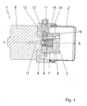
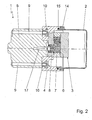
- FIGS. 1 and 2 show a small hydraulic unit 1 shown, the essential components of a pressure medium reservoir 2, one for example as a gear pump trained hydraulic pump 3, a so-called Valve block 4 and an electric motor 5 for driving the Has hydraulic pump 3.
- a pressure medium reservoir 2 one for example as a gear pump trained hydraulic pump 3, a so-called Valve block 4 and an electric motor 5 for driving the Has hydraulic pump 3.
- valve block 4 which in the present case is a plastic injection molded part is formed and, if necessary, metallic reinforcements may include controls for Control of the hydraulic small unit 1 and is used for attachment other components of the small hydraulic unit 1.
- the hydraulic pump 3 essentially comprises three housing parts 6, 7 and 8, wherein the housing part 8 is a pump flange represents for fastening the pump to the valve block 4.
- valve block 4 is in the range of one Recess 12 from a likewise designed as an insert so-called high-pressure insert 11, which one made of a metallic material, for example aluminum, manufactured connector for a not shown here hydraulic consumers, such as a hydraulic cylinder, is.
- high-pressure insert 11 one made of a metallic material, for example aluminum, manufactured connector for a not shown here hydraulic consumers, such as a hydraulic cylinder, is.
- the high-pressure insert 11 has a small hydraulic unit inside 1 lying end 18, which in the to the valve block 4 adjacent pump flange 8 of the hydraulic pump 3 protrudes. In this area is between high pressure use 11 and the pump flange 8 are designed as an O-ring Seal 13 arranged.
- the plate-like pump flange 8, the high pressure insert 11 and the threaded inserts 10 are in the Valve block 4 injected or overmolded with plastic. These components are thus firmly connected to the valve block and form a structural unit with the latter.
- the valve block 4 is also in the area of the anchorage of the Pressure fluid reservoir made of plastic 2 made of plastic.
- the anchorage of the pressure fluid reservoir 2 on the valve block 4 is a bayonet catch 14 executed.
- For sealing the storage container 2 compared to the environment is in the area of the bayonet lock 14 additionally one designed as an O-ring Seal 15 arranged.
Landscapes
- Engineering & Computer Science (AREA)
- Mechanical Engineering (AREA)
- General Engineering & Computer Science (AREA)
- Physics & Mathematics (AREA)
- Fluid Mechanics (AREA)
- Details Of Reciprocating Pumps (AREA)
Applications Claiming Priority (2)
| Application Number | Priority Date | Filing Date | Title |
|---|---|---|---|
| DE10105450 | 2001-02-07 | ||
| DE10105450A DE10105450A1 (de) | 2001-02-07 | 2001-02-07 | Vorrichtung zur Förderung von Hydrauliköl, Schmieröl oder dergleichen |
Publications (2)
| Publication Number | Publication Date |
|---|---|
| EP1231385A1 true EP1231385A1 (fr) | 2002-08-14 |
| EP1231385B1 EP1231385B1 (fr) | 2004-01-14 |
Family
ID=7673104
Family Applications (1)
| Application Number | Title | Priority Date | Filing Date |
|---|---|---|---|
| EP02002243A Expired - Lifetime EP1231385B1 (fr) | 2001-02-07 | 2002-01-30 | Dispositif d'alimentation en huile hydraulique, huile lubrifiante ou analogues |
Country Status (2)
| Country | Link |
|---|---|
| EP (1) | EP1231385B1 (fr) |
| DE (2) | DE10105450A1 (fr) |
Cited By (5)
| Publication number | Priority date | Publication date | Assignee | Title |
|---|---|---|---|---|
| DE20310257U1 (de) * | 2003-07-03 | 2003-11-06 | TRW Fahrwerksysteme GmbH & Co KG, 40547 Düsseldorf | Hydraulikaggregat |
| EP1857674A1 (fr) * | 2006-05-10 | 2007-11-21 | Jungheinrich Aktiengesellschaft | Agrégat hydrophile |
| WO2010057485A1 (fr) * | 2008-11-20 | 2010-05-27 | Wilhelm Karmann Gmbh I. I. | Groupe hydraulique |
| EP2746590A1 (fr) * | 2012-12-19 | 2014-06-25 | Bucher Hydraulics S.p.A. | Unité motrice pour déplacer au moins un actionneur hydraulique |
| WO2017005338A1 (fr) * | 2015-07-08 | 2017-01-12 | Hydac Fluidtechnik Gmbh | Groupe hydraulique |
Families Citing this family (3)
| Publication number | Priority date | Publication date | Assignee | Title |
|---|---|---|---|---|
| FR2847008B1 (fr) * | 2002-11-07 | 2006-04-21 | Ksb Sas | Systeme de robinetterie pour utilisation dans un navire |
| DE102006042619A1 (de) * | 2006-09-04 | 2008-03-20 | Voith Turbo H + L Hydraulic Gmbh & Co. Kg | Baugruppe für Hydraulikanlagen |
| CN107363792B (zh) * | 2017-07-06 | 2023-09-19 | 浙江工业大学 | 一种手持式可更换工作头的电动液压破拆器 |
Citations (2)
| Publication number | Priority date | Publication date | Assignee | Title |
|---|---|---|---|---|
| US5542823A (en) * | 1995-06-14 | 1996-08-06 | Applied Power Inc. | Reservoir body for a radial plunger pump |
| EP1008750A1 (fr) * | 1998-12-07 | 2000-06-14 | Robert Bosch Gmbh | Unité hydraulique compacte |
-
2001
- 2001-02-07 DE DE10105450A patent/DE10105450A1/de not_active Withdrawn
-
2002
- 2002-01-30 EP EP02002243A patent/EP1231385B1/fr not_active Expired - Lifetime
- 2002-01-30 DE DE50200204T patent/DE50200204D1/de not_active Expired - Fee Related
Patent Citations (2)
| Publication number | Priority date | Publication date | Assignee | Title |
|---|---|---|---|---|
| US5542823A (en) * | 1995-06-14 | 1996-08-06 | Applied Power Inc. | Reservoir body for a radial plunger pump |
| EP1008750A1 (fr) * | 1998-12-07 | 2000-06-14 | Robert Bosch Gmbh | Unité hydraulique compacte |
Cited By (5)
| Publication number | Priority date | Publication date | Assignee | Title |
|---|---|---|---|---|
| DE20310257U1 (de) * | 2003-07-03 | 2003-11-06 | TRW Fahrwerksysteme GmbH & Co KG, 40547 Düsseldorf | Hydraulikaggregat |
| EP1857674A1 (fr) * | 2006-05-10 | 2007-11-21 | Jungheinrich Aktiengesellschaft | Agrégat hydrophile |
| WO2010057485A1 (fr) * | 2008-11-20 | 2010-05-27 | Wilhelm Karmann Gmbh I. I. | Groupe hydraulique |
| EP2746590A1 (fr) * | 2012-12-19 | 2014-06-25 | Bucher Hydraulics S.p.A. | Unité motrice pour déplacer au moins un actionneur hydraulique |
| WO2017005338A1 (fr) * | 2015-07-08 | 2017-01-12 | Hydac Fluidtechnik Gmbh | Groupe hydraulique |
Also Published As
| Publication number | Publication date |
|---|---|
| EP1231385B1 (fr) | 2004-01-14 |
| DE10105450A1 (de) | 2002-08-08 |
| DE50200204D1 (de) | 2004-02-19 |
Similar Documents
| Publication | Publication Date | Title |
|---|---|---|
| EP0461212B1 (fr) | Pompe d'injection de carburant a commande electrique pour moteurs a combustion interne, en particulier pompe d'injection combinee avec l'injecteur | |
| EP2079930B1 (fr) | Pompe à piston pour système de freinage de véhicule, munie d'une tige de piston | |
| DE19752545A1 (de) | Kolbenpumpe | |
| EP0935710A1 (fr) | Piston composite avec element d'etancheite integre pour pompe a pistons radiaux installee dans un systeme de freinage de vehicule | |
| DE102009027146A1 (de) | Kraftstoff-Hochdruckpumpe | |
| EP1231385B1 (fr) | Dispositif d'alimentation en huile hydraulique, huile lubrifiante ou analogues | |
| EP2201239B1 (fr) | Pompe d'alimentation en carburant, notamment pour un système d'alimentation en carburant d'un moteur à combustion interne à pistons | |
| DE102014010718B4 (de) | Kolbenpumpe für ein Kraftstoffeinspritzsystem | |
| DE102009019721B4 (de) | Hydraulisches System | |
| DE2423383A1 (de) | Fluidumlaufpumpe | |
| EP1287264B1 (fr) | Appareil hydraulique | |
| EP0662568A1 (fr) | Vérin linéaire | |
| EP3320210B1 (fr) | Groupe hydraulique | |
| DE202014103665U1 (de) | Stator einer Exzenterschneckenpumpe zum Fördern einer fließfähigen Fördermasse, insbesondere einer Baustoffmischung wie Mörtel | |
| DE102007049911A1 (de) | Spann- und Führungsschiene für Kettentriebe | |
| EP3683441B1 (fr) | Unité de montage en tant que module pour une pompe à lubrifiant | |
| DE10118925C1 (de) | Kolbenpumpe | |
| DE10239728A1 (de) | Pumpe, insbesondere für eine Kraftstoffeinspritzeinrichtung für eine Brennkraftmaschine | |
| WO2008058799A1 (fr) | Injecteur de carburant | |
| DE10324303A1 (de) | Verschlusseinrichtung für eine hochdruckbeaufschlagte Bohrung eines Bauteils und Bauteil mit Verschlusseinrichtung | |
| EP3353431A1 (fr) | Câble hélicoïdal pourvu d'un élément d'entraînement et son procédé de fabrication | |
| DE2404077A1 (de) | Ahnstangenlenkung mit integrierter hydraulik-lenkhilfe | |
| DE10346242B4 (de) | Injektorkörper für einen Common Rail Injektor | |
| DE102008057699A1 (de) | Hochdruckpumpe | |
| DE102009057103A1 (de) | Hohlschraube |
Legal Events
| Date | Code | Title | Description |
|---|---|---|---|
| PUAI | Public reference made under article 153(3) epc to a published international application that has entered the european phase |
Free format text: ORIGINAL CODE: 0009012 |
|
| AK | Designated contracting states |
Kind code of ref document: A1 Designated state(s): AT BE CH CY DE DK ES FI FR GB GR IE IT LI LU MC NL PT SE TR |
|
| AX | Request for extension of the european patent |
Free format text: AL;LT;LV;MK;RO;SI |
|
| 17P | Request for examination filed |
Effective date: 20030214 |
|
| AKX | Designation fees paid |
Designated state(s): DE FR IT |
|
| GRAH | Despatch of communication of intention to grant a patent |
Free format text: ORIGINAL CODE: EPIDOS IGRA |
|
| GRAP | Despatch of communication of intention to grant a patent |
Free format text: ORIGINAL CODE: EPIDOSNIGR1 |
|
| GRAS | Grant fee paid |
Free format text: ORIGINAL CODE: EPIDOSNIGR3 |
|
| GRAA | (expected) grant |
Free format text: ORIGINAL CODE: 0009210 |
|
| AK | Designated contracting states |
Kind code of ref document: B1 Designated state(s): DE FR IT |
|
| REG | Reference to a national code |
Ref country code: IE Ref legal event code: FG4D Free format text: GERMAN |
|
| REF | Corresponds to: |
Ref document number: 50200204 Country of ref document: DE Date of ref document: 20040219 Kind code of ref document: P |
|
| REG | Reference to a national code |
Ref country code: IE Ref legal event code: FD4D |
|
| ET | Fr: translation filed | ||
| PLBE | No opposition filed within time limit |
Free format text: ORIGINAL CODE: 0009261 |
|
| STAA | Information on the status of an ep patent application or granted ep patent |
Free format text: STATUS: NO OPPOSITION FILED WITHIN TIME LIMIT |
|
| 26N | No opposition filed |
Effective date: 20041015 |
|
| PGFP | Annual fee paid to national office [announced via postgrant information from national office to epo] |
Ref country code: DE Payment date: 20070313 Year of fee payment: 6 |
|
| PGFP | Annual fee paid to national office [announced via postgrant information from national office to epo] |
Ref country code: IT Payment date: 20080126 Year of fee payment: 7 |
|
| PGFP | Annual fee paid to national office [announced via postgrant information from national office to epo] |
Ref country code: FR Payment date: 20080118 Year of fee payment: 7 |
|
| PG25 | Lapsed in a contracting state [announced via postgrant information from national office to epo] |
Ref country code: DE Free format text: LAPSE BECAUSE OF NON-PAYMENT OF DUE FEES Effective date: 20080801 |
|
| REG | Reference to a national code |
Ref country code: FR Ref legal event code: ST Effective date: 20091030 |
|
| PG25 | Lapsed in a contracting state [announced via postgrant information from national office to epo] |
Ref country code: FR Free format text: LAPSE BECAUSE OF NON-PAYMENT OF DUE FEES Effective date: 20090202 |
|
| PG25 | Lapsed in a contracting state [announced via postgrant information from national office to epo] |
Ref country code: IT Free format text: LAPSE BECAUSE OF NON-PAYMENT OF DUE FEES Effective date: 20090130 |