EP1231391A2 - Faserverstärktes Kunststoffrohr und dieses verwendende Antriebswelle - Google Patents
Faserverstärktes Kunststoffrohr und dieses verwendende Antriebswelle Download PDFInfo
- Publication number
- EP1231391A2 EP1231391A2 EP02002398A EP02002398A EP1231391A2 EP 1231391 A2 EP1231391 A2 EP 1231391A2 EP 02002398 A EP02002398 A EP 02002398A EP 02002398 A EP02002398 A EP 02002398A EP 1231391 A2 EP1231391 A2 EP 1231391A2
- Authority
- EP
- European Patent Office
- Prior art keywords
- pipe
- power transmission
- transmission shaft
- reinforced plastic
- fiber
- Prior art date
- Legal status (The legal status is an assumption and is not a legal conclusion. Google has not performed a legal analysis and makes no representation as to the accuracy of the status listed.)
- Withdrawn
Links
Images


Classifications
-
- F—MECHANICAL ENGINEERING; LIGHTING; HEATING; WEAPONS; BLASTING
- F16—ENGINEERING ELEMENTS AND UNITS; GENERAL MEASURES FOR PRODUCING AND MAINTAINING EFFECTIVE FUNCTIONING OF MACHINES OR INSTALLATIONS; THERMAL INSULATION IN GENERAL
- F16C—SHAFTS; FLEXIBLE SHAFTS; ELEMENTS OR CRANKSHAFT MECHANISMS; ROTARY BODIES OTHER THAN GEARING ELEMENTS; BEARINGS
- F16C3/00—Shafts; Axles; Cranks; Eccentrics
- F16C3/02—Shafts; Axles
- F16C3/026—Shafts made of fibre reinforced resin
-
- F—MECHANICAL ENGINEERING; LIGHTING; HEATING; WEAPONS; BLASTING
- F16—ENGINEERING ELEMENTS AND UNITS; GENERAL MEASURES FOR PRODUCING AND MAINTAINING EFFECTIVE FUNCTIONING OF MACHINES OR INSTALLATIONS; THERMAL INSULATION IN GENERAL
- F16C—SHAFTS; FLEXIBLE SHAFTS; ELEMENTS OR CRANKSHAFT MECHANISMS; ROTARY BODIES OTHER THAN GEARING ELEMENTS; BEARINGS
- F16C2326/00—Articles relating to transporting
- F16C2326/01—Parts of vehicles in general
- F16C2326/06—Drive shafts
Definitions
- the present invention relates to a fiber reinforced plastic pipe for use such as with a propeller shaft or a drive shaft which constitutes part of the power transmission system of a vehicle.
- the present invention also relates to a power transmission shaft incorporating the fiber reinforced plastic pipe.
- Those shafts that constitute the power transmission system of a vehicle include a propeller shaft for transmitting power from the gearbox to the reduction gear, and a drive shaft for coupling the engine and the hub joint. Any of the shafts is provided at the ends thereof with universal joints, and constructed to respond to variations in length and angle resulting from changes in relative position between the gearbox and the reduction gear or between the engine and the hub joint.
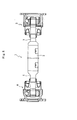
- Fig. 8 is a view illustrating an example of a power transmission shaft, showing the overall view of a propeller shaft 1.
- the propeller shaft 1 is provided with stub shafts 3 and 4, a type of metal joint elements, which are jointed to the both ends of an intermediate shaft 2.
- the stub shafts 3 and 4 mate with the joint inner ring of constant velocity joints 5 and 6 by means of splines or serrations.
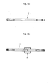
- Figs. 9a and 9b are views illustrating another example of a power transmission shaft, showing an intermediate shaft of the drive shaft.
- Fig. 9a illustrates an intermediate shaft 7 provided with no dynamic damper
- Fig. 9b illustrates an intermediate shaft 8 provided with a dynamic damper 9 for preventing vibrations.
- the FRP pipe can be reduced in thickness and increased in diameter by pultrusion process.
- pultrusion process a plurality of fiber bundles are spun and hardened continuously while being aligned in the longitudinal direction, thereby making it possible to efficiently manufacture a pipe-shaped molded product having a uniform cross-section.
- the FRP pipe is inserted into the metal pipe and then the outer circumference of the metal pipe is reduced in diameter by plastic-working in order to fix the FRP pipe to the metal pipe.
- an adhesive can be injected into the gap between the metal pipe and the FRP pipe.
- the FRP pipe and the metal pipe are formed in the shape of a simple cylinder and have a tolerance of size, respectively, it is necessary to match the dimensions with each other to control subtle press-fitting or press-fit pressures in the process, thereby making the assembly extremely complicated.
- the FRP pipe can be reduced in diameter in the circumferential direction when the FRP pipe is incorporated into the metal pipe. This allows for a plastic deformation by the width of the slit, thereby making the assembly considerably easier in comparison with a case where a cylindrical pipe having no slit is press-fitted into the metal pipe.
- the FRP pipe with a slit is formed to have an outer diameter greater than the inner diameter of the metal pipe, so that the apparent outer diameter of the FRP pipe is less than the inner diameter of the metal pipe when the FRP pipe is elastically deformed by the width of the slit in the circumferential direction.
- the FRP pipe will expand inside the metal pipe back to the original outer diameter provided upon its formation. This elastic recovery force serves to press the FRP pipe against the metal pipe, thereby making it possible to securely fix the FRP pipe to the metal pipe.
- the FRP pipe with a slit when the FRP pipe with a slit is elastically deformed by the width of the slit and thus reduced in diameter, the maximum tensile stress occurs on an outer surface of the pipe, the outer surface being opposite to the slit with respect to the center of the pipe.
- This tensile stress increases in proportion to the width of the slit of the FRP pipe, thereby increasing the possibility of occurrence of cracks.
- reinforcement fibers spun being aligned in the longitudinal direction of the pipe may easily raise the problem that longitudinal or other cracks are also caused by the stress developed due to thermal expansion in addition to the stress caused by an external force.
- the present invention has the following features.
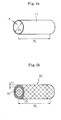
- a metal pipe 11 shown in Fig. 1a is used in combination with an FRP pipe 12 shown in Fig. 1b.
- the FRP pipe 12 which has been reduced in thickness and increased in diameter by pultrusion process, is inserted into the metal pipe 11, for use with a power transmission shaft as its intermediate shaft 2, 7, and 8 (see Figs. 8 and 9).
- the FRP pipe 12 having a high flexural rigidity is disposed inside the metal pipe 11, thereby making it possible to improve the flexural rigidity of the power transmission shaft. This allows for eliminating a support bearing at the intermediate portion or a dynamic damper for preventing vibrations, thereby reducing the shaft in weight and cost and providing an elongated shaft.
- the FRP pipe 12 is inserted into the metal pipe 11 to form the power transmission shaft.
- This makes it possible to provide the shaft with high durability sufficiently enough to withstand a large shearing force for the transmission of power because the shaft has a metallic joint portion at the end portion thereof available for jointing with a joint element. That is, it is possible to employ a joint method, perfect in reliability, such as welding or friction welding for coupling between the metal pipe 11 and the joint element. This makes it possible to perfectly prevent circumferential sliding or axial dislodging, thereby providing the joint portion with long-term reliability.
- FRP layers in combination, of the FRP pipe 12 inserted into the metal pipe 11, the FRP layers having the fibers disposed at angles of 0 degree and ⁇ 45 degrees to the axial direction of the metal pipe 11.
- the FRP pipe 12 is incorporated into the metal pipe 11. Then, for example, the metal pipe 11 is spun to be deformed plastically and reduced in diameter, thereby fixing the FRP pipe 12 to the metal pipe 11 (the portion reduced in diameter is indicated by reference numeral 13 in the figure).
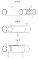
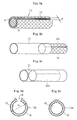
- an FRP pipe 12a having a slit 14 formed in the axial direction As shown in Figs. 3a to 3c, it is also possible to use an FRP pipe 12a having a slit 14 formed in the axial direction.
- the FRP pipe 12a having the slit 14 formed in the axial direction is incorporated into the metal pipe 11, while being reduced in diameter.
- the FRP pipe 12a having the slit 14 eliminates the aforementioned matching and permits a reduced press-fit pressure.
- the slit width W is set to the range from 0.01% to 40% of the outer circumference of the FRP pipe in its natural state.
- a slit width W less than 0.01% of the outer circumference of the FRP pipe may require matching even when the FRP pipe is elastically deformed in the circumferential direction.
- a slit width W greater than 40% of the outer circumference of the FRP pipe may increase the amount of imbalance in rotation, thereby causing a problem of runouts at high speed rotations.
- the cross-sectional shape of the slit 14 is not limited to any particular one, but will be advantageous if the shape can be continuously formed by pultrusion process.
- the FRP pipe 12 may be first formed in the shape of a cylinder and then provided with the slit 14 by cutting.
- an FRP pipe 12b with a slit 14a formed at a bias angle ⁇ with respect to the axial direction.
- the bias angle ⁇ is preferably within ⁇ 30 degrees.
- a slit 14a having a bias angle ⁇ greater than 30 degrees causes the tow to be aligned parallel to that direction. Accordingly, this would make it difficult to improve the flexural rigidity of the power transmission shaft that has incorporated an FRP pipe of fibers having a high elasticity.
- the FRP pipe 12 having the slit 14 is so formed as to have an outer diameter that is greater than the inner diameter of the metal pipe 11, so that the FRP pipe 12 has an apparent outer diameter less than the inner diameter of the metal pipe 11 when having been elastically deformed (reduced in diameter) by the slit width W in the circumferential direction.
- the value of D 1 /D 2 is greater than 1 and less than or equal to 1.3, where D 1 is the outer diameter of the FRP pipe 12 having the slit 14 (see Fig. 3d) and D 2 is the inner diameter of the metal pipe 11 (see Fig. 1a).
- the outer diameter of the FRP pipe 12 having the slit 14 is not greater than the inner diameter of the metal pipe 11, leaving a gap therebetween.
- the value of D 1 /D 2 being greater than 1.3, a deformation caused by a reduction in diameter of the FRP pipe 12 would be beyond the elastic deformation region in some cases, thereby raising a problem of cracks.
- the FRP pipe 12 After having been incorporated into the metal pipe 11, the FRP pipe 12 is to expand therein to restore its original outer diameter given upon its formation. This force acts to press the outer circumference of the FRP pipe 12 against the inner circumference of the metal pipe 11, thereby causing the FRP pipe 12 to be fixed therein. This fixing force is advantageous when the metal pipe 11 is deformed by spinning or by means of adhesive.
- the FRP pipe 12 Upon being reduced in thickness and increased in diameter by pultrusion process, the FRP pipe 12 is spun to align its fiber bundles in the longitudinal direction of the FRP pipe 12 and provided with circumferential reinforced fiber sheet 15 on the outer and inner surface layers of the FRP pipe 12 (see Fig. 1b and other figures).
- the fiber bundles are spun and aligned in the longitudinal direction of the pipe, thereby allowing for making full use of the mechanical properties of the fibers used for the FRP pipe 12 at maximum efficiency.
- the circumferential reinforced fiber sheet 15 is provided on the outer and inner surface layers of the FRP pipe 12, thereby making it possible to prevent tensile strain of the pipe from developing in the circumferential direction.
- the fibers Upon being reduced in thickness and increased in diameter by pultrusion process, the fibers are impregnated with a non-hardened matrix resin and then hardened continuously while those multiple tows are being overwound, thereby making it possible to efficiently manufacture a pipe-shaped molded product having a uniform cross-section.
- the FRP pipe 12 can be formed in advance by sheet wrapping.
- the pultrusion process may be used to significantly reduce the loss of material upon manufacturing, thus providing a better cost advantage in comparison with the sheet wrapping method.
- the FRP pipe 12 can be overwound but may be preferably provided with twenty or less layers in number. This is because a molded product having layers of more than twenty would make the preparation work considerably complicated, thereby compromising its mass productivity.
- the fibers that form the FRP pipe 12 have desirably a low density and a high elasticity in order to provide an increased first-order flexural resonance frequency for the power transmission shaft.
- Such fibers include PAN-based carbon fibers, pitch-based carbon fibers, silicon carbide fibers, alumina fibers, boron fibers, glass fibers, para-based aramid fibers (such as Kevlar made by DU PONT), and metal fibers (of steel, aluminum alloy, titanium alloy, copper, and tungsten).
- fibers in combination to reduce the cost of the FRP pipe 12.
- Such fibers as have a high specific elasticity can greatly contribute to the reduction of weight.
- the PAN-based carbon fibers are preferable in terms of specific strength while the pitch-based carbon fibers are preferable in terms of specific elasticity.
- a hybrid type of fibers such as these carbon fibers combined with each other or these carbon fibers combined with glass fibers.
- the diameter of a fiber is preferably within the range from 1 ⁇ m to 20 ⁇ m or more preferably from 5 ⁇ m to 8 ⁇ m.
- acrylic fibers employed as raw material are costly.
- fibers of diameter larger than 20 ⁇ m it is difficult to provide fibers having a high elasticity.
- mesophasepitch-based carbon fibers are preferably employed which are long fibers and has a high elasticity.
- the fibers which constitute the fiber bundles of the FRP pipe 12 that are spun and aligned in the longitudinal direction, have preferably a tensile elasticity of 196GPa or more, more preferably 245GPa or more.
- the fibers having a tensile elasticity of less than 196GPa would not sufficiently contribute to the improvement of the cross-sectional second-order moment of inertia of the FRP pipe 12 even when the FRP pipe 12 is increased in thickness because the outer diameter thereof remains unchanged. Accordingly, it is difficult to increase the first-order flexural resonance frequency of the power transmission shaft.
- the fibers that form the circumferential reinforced fiber sheet 15 provided on the outer and inner surface layers of the FRP pipe 12. It is necessary for the fibers to have a tensile elasticity sufficiently enough to prevent the circumferential tensile strain that occurs on a surface of the FRP pipe 12a having the slit 14, the surface being opposite to the slit with respect to the center of the pipe, when the FRP pipe 12a is reduced in diameter. In this context, it is desirable for the fibers that form the circumferential reinforced fiber sheet 15 to have a high tensile elasticity of at least 58.8GPa. Such fibers include the PAN-based carbon fibers, pitch-based carbon fibers, glass fibers, and aramid fibers.
- the circumferential reinforced fiber sheet 15 may take the form such as of a randomly chopped mat or a continuously strand mat.
- the circumferential reinforced fiber sheet 15 requires the basis weight (FAW) within the range from 100g/m 2 to 600 g/m 2 , or preferably from 200 g/m 2 to 400 g/m 2 .
- the circumferential reinforced fiber sheet 15 also requires a thickness within the range from 0.05mm to 1.0mm, or preferably from 0.1mm to 0.8mm.
- the fiber sheet 15 of the basis weight (FAW) less than 100g/m 2 or of thickness less than 0.05mm it may be difficult to form a piece of continuous fiber sheet 15 by pultrusion process due to a fracture caused by a tensile force.
- a piece of fiber sheet 15 of the basis weight (FAW) more than 600g/m 2 tends to become wrinkled upon its formation by pultrusion process.
- a piece of fiber sheet 15 of thickness greater than 1.0mm it is difficult to continuously accommodate the fiber sheet 15 in the outer or inner mold upon its formation by pultrusion process.
- the fiber sheet 15 needs not always to be provided on both the outer and inner surface layers. That is, the fiber sheet 15 may be disposed on either the outer surface layer or the inner surface layer, or only on the vicinity of a surface opposite to the slit with respect to the center of the pipe, as long as the fiber sheet 15 can substantially prevent the occurrence of cracks.
- the filament winding of reinforcement fibers such as glass fibers is also acceptable which is formed at a certain angle to the longitudinal direction at the same time of the formation or after the pultrusion process.
- the filament winding employed together with the pultrusion process would require a special apparatus and thus affect productivity. Accordingly, it is advantageous to use the circumferential reinforced fiber sheet 15.
- axial grooves 16 serving as an adhesive-retaining recessed portion between the metal pipe 11 and FRP pipe 12c after having been assembled.
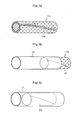
- adhesive-retaining recessed portions include other structures such as circumferential grooves 16a (see Fig. 6a) and recessed portions 16b (see Fig. 6b).
- circumferential grooves 16c as will serve as an adhesive-retaining recessed portion after assembly may be formed plastically in advance on the inner circumferential surface of a metal pipe 11a.
- the adhesive In general, no restriction is imposed on the adhesive to be used as long as the adhesive can bond metal and FRP together.
- all the metal-FRP adhesives can be used which are described in "Science and Reality of Adhesive" published by Kabushiki Kaisha Kobunshi, and "How to Select Adhesive for High Performance” published Kabushiki Kaisha Gijutsu Hyoronsha.
- More desirable adhesives include a structural adhesive which is an epoxy-based adhesive of a solution type containing aluminum powder or iron oxide powder and which enables resistance welding which is typified by spot welding. To correct the balance of the shaft later in its manufacturing process, this weldable adhesive allows balance pieces to be welded onto the shaft without any problem.
- the heat can be used which is applied to the outer circumference of the metal pipe for painting by carbonization.
- thermosetting resin to be used as a matrix for the FRP pipe 12.
- thermosetting resins such as epoxy resin, phenol resin, unsaturated polyester resin, vinyl ester resin of bisphenol A type or novolak type, urethane resin, alkyd resin, xylene resin, melamine resin, furan resin, silicon resin, and polyimide resin.
- epoxy resin or vinyl ester resin it is preferable to use the epoxy resin or vinyl ester resin.
- the resistance to heat of the epoxy resin after having been cured may be 60°C or more in terms of the glass transition temperature, preferably 80°C or more.
- the resistance to heat of the epoxy resin after having been cured may cause a serious problem, and thereby cannot be used as the matrix.
- a modified epoxy resin which contains rubber particles in an epoxy resin to form a sea-island structure and which is thereby provided with resistance to impact. It is also possible to use a modified epoxy resin having principal chains or side chains modified in chemical structure. In this case, it is possible to provide damping properties for the resulting power transmission shaft. It is also possible to use an epoxy resin which is provided with electrical conductivity by distributing fillers such as electrically conductive carbon black or metal powder in the epoxy resin.
- the glass transition temperature after it has been cured may be 60°C or more, preferably 70°C or more.
- a vinyl ester resin having a glass transition temperature of less than 60°C after it has been cured may be reduced in elasticity, resulting in a drop in flexural rigidity of the FRP pipe 12.
- an FRP pipe 12 to be used for insertion is manufactured using the vinyl ester resin as the matrix by pultrusion process.
- an inner mold release agent can be contained in the resin to improve its formidability.
- a surface of reinforcement fibers to be used may be subjected to ozone oxidation or ultraviolet radiation to activate the surface, while a silane coupling agent or titanium coupling agent may be used for wet processing to improve affinity.
- a highly reactive functional group site may be formed on the surface of the fibers and then cured together with a thermosetting matrix resin to thereby provide firm adhesion having a chemical bond.
- metal pipe 11 No particular restriction is imposed on the type of metal for use with the metal pipe 11 as long as the metal permits machining such as boring, welding, friction welding, or press-fitting.
- preferable metals include iron, aluminum, copper, titanium, tungsten, and nickel.
- an alloy of any of these metals may also be used.
- the dimensions of the power transmission shaft made up of the metal pipe 11 and the FRP pipe 12 are determined by the flexural natural frequency required of the power transmission shaft.
- the pipe is to be increased in diameter and weight.
- the thickness of the metal pipe 11 may be designed to satisfy only the necessary static torsional strength, and an FRP pipe 12 having a high elasticity may be inserted into the metal pipe 11 so as to satisfy the flexural natural frequency required for the outer circumference thereof. This makes it possible to reduce the outermost diameter and weight of the shaft.
- Such a metal pipe 11 may have a length of 100mm or more and 6000mm or less, preferably 200mm or more and 6000mm or less.
- the metal pipe 11 has already a high rigidity sufficiently enough to eliminate inserting an FRP pipe 12 into the metal pipe 11.
- a metal pipe 11 greater than 6000mm in length it is difficult to install the pipe in a vehicle even when the vehicle is a truck.
- the axial length of the FRP pipe 12 being inserted into the metal pipe 11 such that the value of FL/PL is within the range from 0.1 to 1.0, where PL is the length of the metal pipe 11 (see Fig. 1a) and FL is the length of the FRP pipe 12 (see Fig. 1b).
- FL/PL is the length of the metal pipe 11 (see Fig. 1a)
- FL is the length of the FRP pipe 12 (see Fig. 1b).
- the value of FL/PL being less than 0.1, it is difficult to achieve the necessary flexural rigidity even when an FRP pipe 12 having a high specific elasticity is incorporated into the metal pipe 11.
- the FRP pipe 12 is longer than the metal pipe 11. That is, this makes it impossible to employ a metal-to-metal joint method appropriately at least on one side of the resulting power transmission shaft.
- the metal pipe 11 is preferably within the range from 1mm to 10mm in thickness.
- a metal pipe 11 having a thickness of 1mm or less may be damaged when carried or the FRP pipe 12 is inserted therein. This also makes it difficult to design the inner diameter and thickness of the metal pipe 11 to satisfy only the static torsional strength required of the power transmission shaft for use with a vehicle. Even when the metal pipe 11 can be designed, the pipe is increased in diameter. A metal pipe 11 of thickness more than 10mm is too heavy to be employed as the shaft for use with a passenger car, thus making it impossible to achieve the object of reducing weight.
- the metal pipe 11 has preferably an outer diameter within the range from 10mm to 250mm, preferably from 15mm to 230mm, more preferably from 20mm to 200mm.
- a metal pipe 11 having an outer diameter of less than 10mm cannot satisfactorily transmit the torque required by a passenger car even with the FRP pipe 12 inserted in the metal pipe 11.
- a metal pipe 11 of outer diameter greater than 250mm would raise a space problem that the pipe interferes with other parts inside the vehicle.
- the value of t 2 /t 1 is within the range of 0.01 to 10, where t 1 is the thickness of the metal pipe 11 (see Fig. 1a) and t 2 is the thickness of the FRP pipe 12 (see Fig. 1b).
- t 1 is the thickness of the metal pipe 11 (see Fig. 1a)
- t 2 is the thickness of the FRP pipe 12 (see Fig. 1b).
- t 2 /t 1 is less than 0.01
- the value of t 2 /t 1 being greater than 10, an improvement can be expected in flexural rigidity when the FRP pipe 12 is incorporated into the metal pipe 11.
- the resulting power transmission shaft provided in this way has sufficient reliability in torsional strength and joint strength required for a vehicle, being light in weight and compact. Furthermore, since a metal surface is available on the outer circumference, it is possible to correct the balance of the shaft or paint the shaft in the existing line and process. Furthermore, the power transmission shaft provides the same performances as those of the current propeller shaft in terms of resistance to hitting stones (or resistance to chipping) during running with passengers in the vehicle and resistance to corrosion due to salt water. In particular, consider the case where the FRP pipe is formed by pultrusion process.
- the step of winding the prepreg sheet, the shrink tape and the step of winding the shrink tape, and the step of curing prepreg sheet (or heat treatment) can be eliminated. This makes it possible to considerably reduce the loss of material upon manufacturing, thereby realizing the reduction of manufacturing costs of the power transmission shaft.
- the present invention is not limited to these examples.
- the hammering method was employed to evaluate flexural rigidity.
- Example 1 the pultrusion process was used to form an FRP pipe (70mm in outer diameter and 3mm in thickness) while the tow of PAN-based carbon fibers of elasticity 255kN/mm 2 , "PYROFIL TRH50 made by Mitsubishi Rayon Co., Ltd.," and a continuous strand mat employing glass fibers of elasticity 72.3kN/mm 2 , "CSM#300 made by Asahi Fiber Glass Co.,” were being impregnated with a vinyl ester resin, "8250H made by Japan U-Pica Co., Ltd.”
- the glass fiber sheet 15 was arranged on the outer and inner surface layers of the FRP pipe 12, while carbon fibers were spun and aligned in the axial direction.
- a slit of 0.8m in length and 9mm in width was provided on the FRP pipe, which was then elastically deformed in the circumferential direction.
- the FRP pipe was inserted into a steel pipe (of STKM13B, 70mm in outer diameter, 1.4mm in thickness, and 0.9m in length) down to the middle portion. Then, the FRP pipe with the slit was allowed to expand in the circumferential direction to be fixed inside the metal pipe.
- a stub shaft was welded to both ends to prepare an intermediate shaft for the propeller shaft.
- the resulting intermediate shaft provided a first-order flexural natural frequency of 140Hz when measured by the hammering method with both ends being supported. This value tells that the propeller shaft can be satisfactorily employed for practical use.
- Example 2 the pultrusion process was used to form an FRP pipe (70mm in outer diameter and 3mm in thickness) while the tow of PAN-based carbon fibers of elasticity 255kN/mm 2 , "PYROFIL TRH50 made by Mitsubishi Rayon Co., Ltd.," and a continuous strand mat employing glass fibers of elasticity 72.3kN/mm 2 , "CSM#300 made by Asahi Fiber Glass Co.,” were being impregnated with a vinyl ester resin, "8250H made by Japan U-Pica Co., Ltd.”
- the glass fiber sheet was arranged on the outer and inner surface layers of the FRP pipe, while carbon fibers were spun and aligned in the axial direction.
- a slit of 0.8m in length and 9mm in width was provided on the FRP pipe, which was then elastically deformed in the circumferential direction.
- the FRP pipe was inserted into a steel pipe (of STKM13B, 70mm in outer diameter, 1.4mm in thickness, and 0.9m in length) down to the middle portion. Then, the FRP pipe was adhered to the metal pipe with an adhesive, "Penguin Cement #1081L made by Sunstar Engineering Inc.”
- a stub shaft was welded to both ends to prepare an intermediate shaft for the propeller shaft.
- the resulting intermediate shaft provided a first-order flexural natural frequency of 143Hz when measured by the hammering method with both ends being supported. This value tells that the propeller shaft can be satisfactorily employed for practical use.
- an FRP pipe was spun in the same way as in the aforementioned examples without using the glass fiber sheet.
- a slit of width 9mm was provided on the FRP pipe, which was then elastically deformed in the circumferential direction.
Landscapes
- Engineering & Computer Science (AREA)
- General Engineering & Computer Science (AREA)
- Ocean & Marine Engineering (AREA)
- Mechanical Engineering (AREA)
- Shafts, Cranks, Connecting Bars, And Related Bearings (AREA)
- Motor Power Transmission Devices (AREA)
- Moulding By Coating Moulds (AREA)
Applications Claiming Priority (2)
| Application Number | Priority Date | Filing Date | Title |
|---|---|---|---|
| JP2001031005A JP4846103B2 (ja) | 2001-02-07 | 2001-02-07 | 繊維強化樹脂パイプ及びこれを用いた動力伝達シャフト |
| JP2001031005 | 2001-02-07 |
Publications (2)
| Publication Number | Publication Date |
|---|---|
| EP1231391A2 true EP1231391A2 (de) | 2002-08-14 |
| EP1231391A3 EP1231391A3 (de) | 2004-11-03 |
Family
ID=18895146
Family Applications (1)
| Application Number | Title | Priority Date | Filing Date |
|---|---|---|---|
| EP02002398A Withdrawn EP1231391A3 (de) | 2001-02-07 | 2002-01-31 | Faserverstärktes Kunststoffrohr und dieses verwendende Antriebswelle |
Country Status (3)
| Country | Link |
|---|---|
| US (1) | US8118064B2 (de) |
| EP (1) | EP1231391A3 (de) |
| JP (1) | JP4846103B2 (de) |
Cited By (6)
| Publication number | Priority date | Publication date | Assignee | Title |
|---|---|---|---|---|
| GB2406154A (en) * | 2003-09-17 | 2005-03-23 | Cromton Technology Group Ltd | Composite shaft with metal sleeve |
| DE102008056018A1 (de) * | 2008-11-05 | 2010-05-06 | Rolls-Royce Deutschland Ltd & Co Kg | Triebwerkswelle für ein Gasturbinentriebwerk |
| DE102009037049A1 (de) * | 2009-08-13 | 2011-02-17 | Rolls-Royce Deutschland Ltd & Co Kg | Triebwerkswelle in hybrider Bauweise |
| EP2546432A1 (de) * | 2011-07-11 | 2013-01-16 | Trumpf Sachsen GmbH | Verfahren und Vorrichtung zum Versteifen eines Hohlprofils, insbesondere des äußeren Hohlprofils eines Führungsträgers für eine Bewegungseinheit einer Werkzeugmaschine |
| EP2444633A3 (de) * | 2010-10-19 | 2014-07-02 | Rolls-Royce Deutschland & Co. KG | Antriebswelle, insbesondere Radialwelle für ein Gasturbinentriebwerk, mit Faserverbundschichten |
| EP2496856A4 (de) * | 2009-11-03 | 2015-04-22 | Gkn Driveline North America | Dämpfer für atemmodus |
Families Citing this family (36)
| Publication number | Priority date | Publication date | Assignee | Title |
|---|---|---|---|---|
| US6863763B2 (en) * | 2002-10-23 | 2005-03-08 | Korea Advanced Institute Of Science And Technology | Hybrid propeller shaft made of metal and composite material and method of manufacturing the same |
| DE10340661B4 (de) * | 2003-09-04 | 2007-12-20 | Hilti Ag | Verlängerung für eine Durchführung |
| US7069956B1 (en) | 2003-10-23 | 2006-07-04 | Mosier James W | Marina piping |
| US20050257847A1 (en) * | 2004-05-24 | 2005-11-24 | Alenia Aeronautica S.P.A. | Multi-layer duct for air distribution in air conditioning systems for vehicles, in particular aircrafts, and an element for fixing the duct to the structure of an aircraft |
| US7271721B2 (en) * | 2004-05-28 | 2007-09-18 | Lockheed Martin Corporation | Protected distribution system |
| US7318650B2 (en) * | 2005-06-01 | 2008-01-15 | Lang-Mekra North America, Llc | Tapered tube lock connector for a vehicle mirror mounting assembly |
| KR101041448B1 (ko) | 2005-10-21 | 2011-06-16 | 세메스 주식회사 | 반송 샤프트 및 반송 샤프트의 제조방법 |
| US20070104934A1 (en) * | 2005-11-10 | 2007-05-10 | General Electric Company | Lightweight nacelle for turbines and methods for making same |
| KR100588817B1 (ko) | 2006-02-03 | 2006-06-12 | 서병옥 | 합성수지 샤프트 제조방법 |
| JP4850551B2 (ja) * | 2006-03-22 | 2012-01-11 | 京セラケミカル株式会社 | 搬送用シャフト |
| FR2917474B1 (fr) * | 2007-06-18 | 2009-08-07 | Skf Aerospace France Soc Par A | Arbre de transmission de mouvements et/ou d'efforts en rotation |
| JP2009039962A (ja) * | 2007-08-09 | 2009-02-26 | Kyocera Chemical Corp | コンポジットパイプ及びその製造方法 |
| EP2123426A1 (de) * | 2008-05-23 | 2009-11-25 | Rockwool International A/S | Rohrstück und Herstellungsverfahren dafür |
| US7910817B1 (en) * | 2009-09-22 | 2011-03-22 | Ming-Fang Huang | Drum |
| JP5732298B2 (ja) * | 2011-03-31 | 2015-06-10 | 株式会社オーク製作所 | 高密度炭素繊維充填バルク |
| TW201238651A (en) * | 2011-03-31 | 2012-10-01 | Univ Shinshu | Carbon fiber bulk |
| US10464656B2 (en) | 2011-11-03 | 2019-11-05 | The Boeing Company | Tubular composite strut having internal stiffening and method for making the same |
| US10457011B2 (en) * | 2011-11-03 | 2019-10-29 | The Boeing Company | Composite columnar structure having co-bonded reinforcement and fabrication method |
| EP2602496A1 (de) * | 2011-12-05 | 2013-06-12 | Magna Steyr Fahrzeugtechnik AG & Co KG | Verbindung zwischen zwei Bauteilen und Verfahren zur Verbindung zweier Bauteile |
| KR101591307B1 (ko) * | 2013-08-30 | 2016-02-04 | 한국철도기술연구원 | 탄소섬유로 구성된 차축을 포함한 전동차용 직결구동방식 견인전동기 |
| CN105020252A (zh) * | 2014-04-28 | 2015-11-04 | 卡尔迈尔纺织机械制造有限公司 | 纺织机的部件 |
| JP6559414B2 (ja) * | 2014-11-17 | 2019-08-14 | Ntn株式会社 | 動力伝達シャフト |
| JP2016137770A (ja) * | 2015-01-26 | 2016-08-04 | 公益財団法人鉄道総合技術研究所 | 連結装置及び動力伝達装置 |
| JP6522356B2 (ja) * | 2015-02-03 | 2019-05-29 | Ntn株式会社 | 動力伝達シャフト |
| KR101664682B1 (ko) | 2015-04-14 | 2016-10-10 | 현대자동차주식회사 | 자동차용 중공 드라이브 샤프트 및 이의 제조방법 |
| US10077857B2 (en) | 2015-06-05 | 2018-09-18 | Advanced Drainage Systems Inc. | Pipe with an outer wrap |
| US9759354B2 (en) | 2015-06-05 | 2017-09-12 | Advanced Drainage Systems, Inc. | Pipe with an outer wrap |
| US10077856B2 (en) | 2015-06-05 | 2018-09-18 | Advanced Drainage Systems Inc. | Pipe with an outer wrap |
| CN105304189A (zh) * | 2015-12-04 | 2016-02-03 | 江苏亨通电力特种导线有限公司 | 一种不锈钢包碳纤维单线及其对应的制作工艺 |
| US9950786B2 (en) * | 2015-12-21 | 2018-04-24 | Goodrich Corporation | Aircraft axle insert to mitigate vibration |
| US11131247B2 (en) | 2018-01-30 | 2021-09-28 | General Electric Company | Additively manufactured rotating shaft |
| US12179913B2 (en) * | 2018-08-24 | 2024-12-31 | Hamilton Sundstrand Corporation | Ballistic resistant drive shaft |
| US11480528B2 (en) | 2018-09-28 | 2022-10-25 | Hamilton Sundstrand Corporation | And inspection method of aircraft drive shafts |
| CN113286695B (zh) * | 2019-04-25 | 2023-03-21 | 日东纺绩株式会社 | 纤维强化树脂中空圆筒体 |
| CN111619137B (zh) * | 2020-06-20 | 2024-10-18 | 河北和风科技开发有限公司 | 一种单丝积压自缠绕拉挤玻璃钢电缆管生产线及制备工艺 |
| WO2022065179A1 (ja) * | 2020-09-24 | 2022-03-31 | 日立Astemo株式会社 | 繊維強化樹脂管体の製造方法 |
Family Cites Families (36)
| Publication number | Priority date | Publication date | Assignee | Title |
|---|---|---|---|---|
| GB669019A (en) | 1950-07-26 | 1952-03-26 | Hardy Spicer & Co Ltd | Improvements relating to tubular drive shafts |
| US3002534A (en) * | 1956-10-29 | 1961-10-03 | Reinhold Engineering & Plastic | Reinforced thermoplastics |
| US3900556A (en) * | 1968-11-20 | 1975-08-19 | Celanese Corp | Process for the continuous carbonization and graphitization of a stabilized acrylic fibrous material |
| US3775520A (en) * | 1970-03-09 | 1973-11-27 | Celanese Corp | Carbonization/graphitization of poly-acrylonitrile fibers containing residual spinning solvent |
| US3954950A (en) * | 1970-03-09 | 1976-05-04 | Celanese Corporation | Production of high tenacity graphitic fibrous materials |
| US4265951A (en) * | 1978-03-27 | 1981-05-05 | Celanese Corporation | Fiber reinforced composite shaft with metallic connector sleeves mounted by longitudinal groove interlock |
| US4171626A (en) * | 1978-03-27 | 1979-10-23 | Celanese Corporation | Carbon fiber reinforced composite drive shaft |
| US4272971A (en) * | 1979-02-26 | 1981-06-16 | Rockwell International Corporation | Reinforced tubular structure |
| US4238540A (en) * | 1979-05-29 | 1980-12-09 | Celanese Corporation | Fiber reinforced composite shaft with metallic connector sleeves mounted by connector ring interlock |
| US4248062A (en) * | 1979-10-05 | 1981-02-03 | Shakespeare Company | Drive shaft assembly and method for making same |
| US4445257A (en) | 1980-08-29 | 1984-05-01 | Rubber-En Kunststoffabriek Enbi B.V. | Conveyor shaft provided with rubber rollers, and method and apparatus for making same |
| JPS5881129A (ja) * | 1981-11-09 | 1983-05-16 | Dainippon Printing Co Ltd | 電線被覆用テープ |
| JPS5881229U (ja) | 1981-11-30 | 1983-06-01 | 凸版印刷株式会社 | 溝付ボ−ド |
| FR2546473B1 (fr) * | 1983-05-24 | 1987-12-11 | Verre Tisse Sa | Materiau tubulaire a base d'une resine renforcee par une matiere textile et cadre de bicyclette ou vehicule similaire realise a partir d'un tel materiau |
| US4888224A (en) * | 1986-04-30 | 1989-12-19 | Dana Corporation | Composite tubular elements and methods of fabrication |
| NO882936D0 (no) * | 1987-07-07 | 1988-07-01 | Nl Mini Welzijn Gesund Cultur | Flerverdig meningokokkvaksine. |
| JPS6491117A (en) * | 1987-10-02 | 1989-04-10 | Alps Electric Co Ltd | Liquid crystal display element |
| JPH01108031A (ja) * | 1987-10-21 | 1989-04-25 | Mitsubishi Electric Corp | 繊維強化プラスチック製動力推進軸の製造方法 |
| JPH0191117U (de) | 1987-12-08 | 1989-06-15 | ||
| JPH0257712A (ja) * | 1988-08-23 | 1990-02-27 | Nitto Denko Corp | プラスチック製ドライブシヤフト |
| JPH0669733B2 (ja) * | 1990-11-29 | 1994-09-07 | 株式会社袋谷製作所 | 加熱発泡性樹脂とカーボン繊維を組み合わせた軸状部材およびその製造方法 |
| US5439416A (en) * | 1990-12-24 | 1995-08-08 | Xerox Corporation | Composite shaft with integrally molded functional feature |
| EP0509480B1 (de) | 1991-04-18 | 1998-07-01 | Suehiro Kogyo Co., Ltd. | Mehrschichtige Röhre |
| JP3193082B2 (ja) * | 1991-10-17 | 2001-07-30 | 富士重工業株式会社 | 繊維強化プラスチック製荷重伝達軸 |
| JP3508941B2 (ja) * | 1993-12-13 | 2004-03-22 | 東レ株式会社 | プロペラシャフト |
| US5881775A (en) * | 1994-10-24 | 1999-03-16 | Hexcel Corporation | Heat exchanger tube and method for making |
| US5921285A (en) * | 1995-09-28 | 1999-07-13 | Fiberspar Spoolable Products, Inc. | Composite spoolable tube |
| EP0774595B1 (de) * | 1995-11-16 | 2002-05-08 | The B.F. Goodrich Company | Verschachtelte Dämpfungsvorrichtung mit relativer Bewegung |
| JP3582322B2 (ja) * | 1997-09-12 | 2004-10-27 | 三菱自動車工業株式会社 | プロペラシャフト |
| US6464591B1 (en) * | 1998-06-26 | 2002-10-15 | Ntn Corporation | Power transmission shaft |
| US6287209B1 (en) * | 1999-01-28 | 2001-09-11 | Ntn Corporation | Propeller shaft and method of producing the same |
| US6517440B2 (en) * | 1999-04-16 | 2003-02-11 | Xerox Corporation | Plastic shafts with molded core and external feature |
| JP3296328B2 (ja) * | 1999-05-11 | 2002-06-24 | 株式会社豊田自動織機 | 繊維強化プラスチック製パイプ |
| JP2001027220A (ja) * | 1999-07-12 | 2001-01-30 | Ntn Corp | 動力伝達シャフト |
| JP2001047883A (ja) * | 1999-08-05 | 2001-02-20 | Ntn Corp | 動力伝達シャフト |
| US6561229B2 (en) * | 2000-06-26 | 2003-05-13 | Raymond L. Wellman | Electrostatic charge neutralizing fume duct with continuous carbon fiber |
-
2001
- 2001-02-07 JP JP2001031005A patent/JP4846103B2/ja not_active Expired - Lifetime
-
2002
- 2002-01-29 US US10/058,064 patent/US8118064B2/en active Active
- 2002-01-31 EP EP02002398A patent/EP1231391A3/de not_active Withdrawn
Cited By (9)
| Publication number | Priority date | Publication date | Assignee | Title |
|---|---|---|---|---|
| GB2406154A (en) * | 2003-09-17 | 2005-03-23 | Cromton Technology Group Ltd | Composite shaft with metal sleeve |
| GB2406154B (en) * | 2003-09-17 | 2007-01-03 | Crompton Technology Group Ltd | Hybrid composite transmission shaft |
| DE102008056018A1 (de) * | 2008-11-05 | 2010-05-06 | Rolls-Royce Deutschland Ltd & Co Kg | Triebwerkswelle für ein Gasturbinentriebwerk |
| US8251830B2 (en) | 2008-11-05 | 2012-08-28 | Rolls-Royce Deutschland Ltd Co KG | Engine shaft for a gas-turbine engine |
| DE102009037049A1 (de) * | 2009-08-13 | 2011-02-17 | Rolls-Royce Deutschland Ltd & Co Kg | Triebwerkswelle in hybrider Bauweise |
| US8647011B2 (en) | 2009-08-13 | 2014-02-11 | Rolls-Royce Deutschland Ltd & Co Kg | Engine shaft of hybrid design |
| EP2496856A4 (de) * | 2009-11-03 | 2015-04-22 | Gkn Driveline North America | Dämpfer für atemmodus |
| EP2444633A3 (de) * | 2010-10-19 | 2014-07-02 | Rolls-Royce Deutschland & Co. KG | Antriebswelle, insbesondere Radialwelle für ein Gasturbinentriebwerk, mit Faserverbundschichten |
| EP2546432A1 (de) * | 2011-07-11 | 2013-01-16 | Trumpf Sachsen GmbH | Verfahren und Vorrichtung zum Versteifen eines Hohlprofils, insbesondere des äußeren Hohlprofils eines Führungsträgers für eine Bewegungseinheit einer Werkzeugmaschine |
Also Published As
| Publication number | Publication date |
|---|---|
| JP2002235726A (ja) | 2002-08-23 |
| US8118064B2 (en) | 2012-02-21 |
| EP1231391A3 (de) | 2004-11-03 |
| JP4846103B2 (ja) | 2011-12-28 |
| US20020117228A1 (en) | 2002-08-29 |
Similar Documents
| Publication | Publication Date | Title |
|---|---|---|
| US8118064B2 (en) | Fiber reinforced plastic pipe and power transmission shaft employing the same | |
| US6409606B1 (en) | Power transmission shaft | |
| US5601493A (en) | Drive shaft made of fiber reinforced plastics, and method for connecting pipe made of fire-reinforced plastics | |
| Kim et al. | Design and manufacture of an automotive hybrid aluminum/composite drive shaft | |
| US7874925B2 (en) | Transmission shaft joint design | |
| GB2051306A (en) | Fibre-reinforced composite shaft with metal connector sleeves | |
| US6287209B1 (en) | Propeller shaft and method of producing the same | |
| GB2058292A (en) | Fiber-reinforced composite shafts with metallic connector sleeves | |
| US6190263B1 (en) | Propeller shaft including compressive load transmitting section | |
| US6464591B1 (en) | Power transmission shaft | |
| JPH1132455A (ja) | 複合電動機シャフト | |
| JPH06200951A (ja) | 繊維強化樹脂製駆動力伝達用シャフトおよび繊維強化樹脂製パイプの接合方法 | |
| EP0683328B1 (de) | Antriebswelle | |
| JP2001032819A (ja) | 動力伝達シャフト及びプロペラシャフト | |
| GB2406154A (en) | Composite shaft with metal sleeve | |
| US7543895B2 (en) | Metal-sheathed composite vehicle axle | |
| JP2007271079A (ja) | トルク伝達軸 | |
| KR102039819B1 (ko) | 가요성 조인트 커플러 | |
| KR101999277B1 (ko) | 자동차용 cfrp 프로펠러샤프트 | |
| WO2016175536A1 (ko) | 하이브리드 드라이브 샤프트 및 그 제조방법 | |
| JP6917932B2 (ja) | 動力伝達軸 | |
| KR101588846B1 (ko) | 자동차용 프로펠러 샤프트 제조 방법 및 그 제품 | |
| JP2001027220A (ja) | 動力伝達シャフト | |
| KR20110051988A (ko) | 자동차용 프로펠러 샤프트 | |
| US7338380B2 (en) | Composite shaft end assembly and composite shaft formed therewith |
Legal Events
| Date | Code | Title | Description |
|---|---|---|---|
| PUAI | Public reference made under article 153(3) epc to a published international application that has entered the european phase |
Free format text: ORIGINAL CODE: 0009012 |
|
| AK | Designated contracting states |
Kind code of ref document: A2 Designated state(s): AT BE CH CY DE DK ES FI FR GB GR IE IT LI LU MC NL PT SE TR |
|
| AX | Request for extension of the european patent |
Free format text: AL;LT;LV;MK;RO;SI |
|
| PUAL | Search report despatched |
Free format text: ORIGINAL CODE: 0009013 |
|
| AK | Designated contracting states |
Kind code of ref document: A3 Designated state(s): AT BE CH CY DE DK ES FI FR GB GR IE IT LI LU MC NL PT SE TR |
|
| AX | Request for extension of the european patent |
Extension state: AL LT LV MK RO SI |
|
| RIC1 | Information provided on ipc code assigned before grant |
Ipc: 7F 16L 9/133 B Ipc: 7F 16C 3/02 A |
|
| AKX | Designation fees paid | ||
| REG | Reference to a national code |
Ref country code: DE Ref legal event code: 8566 |
|
| STAA | Information on the status of an ep patent application or granted ep patent |
Free format text: STATUS: THE APPLICATION IS DEEMED TO BE WITHDRAWN |
|
| 18D | Application deemed to be withdrawn |
Effective date: 20050504 |