EP1231401A2 - Selbstverstärkende Scheibenbremse - Google Patents
Selbstverstärkende Scheibenbremse Download PDFInfo
- Publication number
- EP1231401A2 EP1231401A2 EP02250837A EP02250837A EP1231401A2 EP 1231401 A2 EP1231401 A2 EP 1231401A2 EP 02250837 A EP02250837 A EP 02250837A EP 02250837 A EP02250837 A EP 02250837A EP 1231401 A2 EP1231401 A2 EP 1231401A2
- Authority
- EP
- European Patent Office
- Prior art keywords
- rotor member
- friction
- movable
- servoed
- brake
- Prior art date
- Legal status (The legal status is an assumption and is not a legal conclusion. Google has not performed a legal analysis and makes no representation as to the accuracy of the status listed.)
- Withdrawn
Links
- 230000000153 supplemental effect Effects 0.000 claims abstract description 8
- 230000000712 assembly Effects 0.000 description 4
- 238000000429 assembly Methods 0.000 description 4
- 230000007246 mechanism Effects 0.000 description 2
- 230000004048 modification Effects 0.000 description 1
- 238000012986 modification Methods 0.000 description 1
- 239000013589 supplement Substances 0.000 description 1
Images
Classifications
-
- F—MECHANICAL ENGINEERING; LIGHTING; HEATING; WEAPONS; BLASTING
- F16—ENGINEERING ELEMENTS AND UNITS; GENERAL MEASURES FOR PRODUCING AND MAINTAINING EFFECTIVE FUNCTIONING OF MACHINES OR INSTALLATIONS; THERMAL INSULATION IN GENERAL
- F16D—COUPLINGS FOR TRANSMITTING ROTATION; CLUTCHES; BRAKES
- F16D55/00—Brakes with substantially-radial braking surfaces pressed together in axial direction, e.g. disc brakes
- F16D55/02—Brakes with substantially-radial braking surfaces pressed together in axial direction, e.g. disc brakes with axially-movable discs or pads pressed against axially-located rotating members
- F16D55/22—Brakes with substantially-radial braking surfaces pressed together in axial direction, e.g. disc brakes with axially-movable discs or pads pressed against axially-located rotating members by clamping an axially-located rotating disc between movable braking members, e.g. movable brake discs or brake pads
- F16D55/224—Brakes with substantially-radial braking surfaces pressed together in axial direction, e.g. disc brakes with axially-movable discs or pads pressed against axially-located rotating members by clamping an axially-located rotating disc between movable braking members, e.g. movable brake discs or brake pads with a common actuating member for the braking members
-
- F—MECHANICAL ENGINEERING; LIGHTING; HEATING; WEAPONS; BLASTING
- F16—ENGINEERING ELEMENTS AND UNITS; GENERAL MEASURES FOR PRODUCING AND MAINTAINING EFFECTIVE FUNCTIONING OF MACHINES OR INSTALLATIONS; THERMAL INSULATION IN GENERAL
- F16D—COUPLINGS FOR TRANSMITTING ROTATION; CLUTCHES; BRAKES
- F16D65/00—Parts or details
- F16D65/02—Braking members; Mounting thereof
- F16D65/12—Discs; Drums for disc brakes
-
- F—MECHANICAL ENGINEERING; LIGHTING; HEATING; WEAPONS; BLASTING
- F16—ENGINEERING ELEMENTS AND UNITS; GENERAL MEASURES FOR PRODUCING AND MAINTAINING EFFECTIVE FUNCTIONING OF MACHINES OR INSTALLATIONS; THERMAL INSULATION IN GENERAL
- F16D—COUPLINGS FOR TRANSMITTING ROTATION; CLUTCHES; BRAKES
- F16D65/00—Parts or details
- F16D65/02—Braking members; Mounting thereof
- F16D2065/13—Parts or details of discs or drums
- F16D2065/1304—Structure
- F16D2065/1316—Structure radially segmented
-
- F—MECHANICAL ENGINEERING; LIGHTING; HEATING; WEAPONS; BLASTING
- F16—ENGINEERING ELEMENTS AND UNITS; GENERAL MEASURES FOR PRODUCING AND MAINTAINING EFFECTIVE FUNCTIONING OF MACHINES OR INSTALLATIONS; THERMAL INSULATION IN GENERAL
- F16D—COUPLINGS FOR TRANSMITTING ROTATION; CLUTCHES; BRAKES
- F16D65/00—Parts or details
- F16D65/02—Braking members; Mounting thereof
- F16D2065/13—Parts or details of discs or drums
- F16D2065/1304—Structure
- F16D2065/132—Structure layered
-
- F—MECHANICAL ENGINEERING; LIGHTING; HEATING; WEAPONS; BLASTING
- F16—ENGINEERING ELEMENTS AND UNITS; GENERAL MEASURES FOR PRODUCING AND MAINTAINING EFFECTIVE FUNCTIONING OF MACHINES OR INSTALLATIONS; THERMAL INSULATION IN GENERAL
- F16D—COUPLINGS FOR TRANSMITTING ROTATION; CLUTCHES; BRAKES
- F16D2125/00—Components of actuators
- F16D2125/18—Mechanical mechanisms
- F16D2125/20—Mechanical mechanisms converting rotation to linear movement or vice versa
- F16D2125/34—Mechanical mechanisms converting rotation to linear movement or vice versa acting in the direction of the axis of rotation
- F16D2125/36—Helical cams, Ball-rotating ramps
- F16D2125/38—Helical cams, Ball-rotating ramps with plural cam or ball-ramp mechanisms arranged concentrically with the brake rotor axis
-
- F—MECHANICAL ENGINEERING; LIGHTING; HEATING; WEAPONS; BLASTING
- F16—ENGINEERING ELEMENTS AND UNITS; GENERAL MEASURES FOR PRODUCING AND MAINTAINING EFFECTIVE FUNCTIONING OF MACHINES OR INSTALLATIONS; THERMAL INSULATION IN GENERAL
- F16D—COUPLINGS FOR TRANSMITTING ROTATION; CLUTCHES; BRAKES
- F16D2127/00—Auxiliary mechanisms
- F16D2127/08—Self-amplifying or de-amplifying mechanisms
- F16D2127/10—Self-amplifying or de-amplifying mechanisms having wedging elements
Definitions
- This invention relates to a self-servoing disc brake assembly, and more specifically, the invention relates to a servoing disc brake rotor.
- Servo-type rotor assemblies have been used for various brake applications.
- Servo rotors typically include a pair of annular members spaced apart from one another.
- the surfaces of the annular members that face one another include ramped pockets that receive a plurality of balls therebetween.
- the balls and ramps cause the members to move away from one another. That is, as the members are rotated relative to one another, the rotor assembly becomes wider.
- Such rotor assemblies have been used as brake adjusters in brake actuators. As the friction members wear in the brake assembly the servo rotor members are rotated relative to one another to take up clearance in the brake assembly due to wear. The servo rotors for these applications do not create any braking force.
- Servo rotors assemblies have also been used to apply a braking force to rotating members in a vehicle.
- An annular housing having a U-shaped cross-section is attached to a rotating member such as a vehicle wheel or clutch.
- the servo rotor is disposed within the housing.
- Outer surfaces of the annular rotor members have friction linings adjacent to the housing.
- At least one hydraulic actuator interconnects the arcuate members for moving the members rotationally relative to one another.
- the friction lining on the members engage the housing to apply a braking force and slow the rotating member.
- the servo rotors for these applications have been the only braking force and have not been used to supplement conventional braking mechanisms.
- a particular brake input force will provide a particular brake torque. It is desirable to increase the brake torque without increasing the brake input force.
- providing additional brake torque has required either additional braking mechanisms that have additional actuators or more robust brake components that can provide the higher brake input force. Therefore, what is needed is a passive brake component that is capable of providing a supplemental brake clamping force to current brake input forces and provide an increased brake torque.
- the present invention provides a self-servoing disc brake assembly that includes a driven rotor member having a first inner surface with a plurality of first pockets.
- the driven rotor member also includes a first friction surface spaced from the first inner surface.
- a movable rotor member is supported on the driven rotor member and is movable relative to the driven rotor member between non-servoed and servoed positions.
- the friction surfaces are spaced a first distance in the non-servo position, and the friction surfaces are spaced a second distance which is greater than a first distance in the servo position.
- the movable rotor member includes a second inner surface with a plurality of second pockets adjacent to the first inner surface and a friction surface spaced from the second inner surface.
- a plurality of balls are arranged between the first and second pockets with at least one of the first and second pockets being ramped.
- a friction member such as a disc brake pad, is arranged adjacent to the first friction surface and is movable between engaged and non-engaged positions. The friction member is spaced from the second friction surface in the non-engaged position and the friction member is in contact with the second friction surface in the engaged position to rotate the movable rotor member to the servoed position and produce a supplemental brake clamping force.
- a shear force is created on the second friction surface. The shear force causes the movable rotor member to rotate relative to and away from the driven rotor member. As a result, for a particular brake input force a larger braking torque is achieved.
- the above invention provides a passive brake component that is capable of providing a supplemental brake clamping force to current brake input forces to provide an increased brake torque.
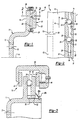
- a brake assembly 10 of the present invention is shown in Figure 1.
- the brake assembly 10 includes a driven rotor member 11 that has a hub 12 and a plurality of apertures 13 for securing the driven rotor member 11 to an axle.
- a movable rotor member 14 is supported on the driven rotor member 11 for movement relative thereto.
- Driven rotor member 11 has a first friction surface 16 and a first inner surface 18 spaced from the first friction surface 16.
- the movable rotor member 14 includes a second inner surface 20 which faces the first inner surface 18, and a second friction surface 22 spaced from the second inner surface 20.
- the friction surfaces 16, 22 are annular and are adapted to be engaged by friction linings, or brake pads, as is known in the art.
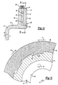
- the inner surfaces 18, 20 include first 30 and second 32 pockets, respectively.
- a plurality of balls 24 are arranged between the inner surfaces 18, 20 and received in the pockets 30, 32.
- Biasing springs 26 interconnect the driven 11 and movable 14 rotor members to seat the balls 24 in the pockets 30, 32.
- the first 30 and second 32 pockets include ramped surfaces 31, 33, respectively, which are inclined in a direction opposite one another.
- the biasing springs 26 seat the balls into the deepest parts of the pockets 30, 32 so that the movable rotor member 14 is at its closest position to the driven rotor member 11 in a non-servoed position N.
- the biasing springs 26 may be of any configuration.
- the biasing springs may include a Belleville spring 26a and a retainer 26b for retaining the Belleville spring 26a onto the driven rotor member 11, as shown in Figure 3.
- the brake assembly 10 includes a caliper 40, as is known in the art, and brake pads 42 adjacent to the friction surfaces 16, 22.
- An actuator 44 which is shown schematically in Figure 3, forces the brake pads 42 into engagement with the friction surfaces 16, 22 in response to a particular brake input force.
- the driven 11 and movable 14 rotor members are driven together about axis A in a direction of rotation R.
- a shear force F is generated on second friction surface 22.
- the shear force F causes the movable rotor member 14 to move in a direction opposite the direction of rotation R.
- the balls 24 move along the ramp surfaces 31, 33 and cause the movable member 14 to move away from the driven rotor member 11.
- the members may include interlocking recesses 50 and protrusions 52.
- One of the rotor members, such as the driven rotor member 11, may include a plurality of recesses 50 for receiving the protrusions 52 extending from the movable rotor member 14. In this manner, the rotor members 11, 14 are interlocked so that the rotor members 11, 14 rotate together in the direction of rotation R when the brake pads 42 are in the non-engaged position.
- the recesses 50 and protrusions 52 permit relative rotation between the rotor members 11, 14 when the shear force F is created on the second friction surface 22 by the brake pads 42 so that the movable rotor member 14 may rotate relative to and away from the driven rotor member 11.
- the driven rotor member is driven about an axis A.
- the brake pads are moved from a non-engaged position into engagement with the friction surfaces 16, 22 in an engaged position.
- a shear force F is created on the second friction surface 22 of the movable rotor member 14.
- the shear force F causes the movable rotor member 14 to rotate relative to and away from the driven rotor member 11.
- the balls 24 move up the ramped surfaces 31, 33.
- the friction surfaces 16, 22 are spaced from one another a first distance.
- the distance between the friction surfaces 16, 22 increases.
- the increased width of the rotor members 11, 14 generates a supplemental brake clamping force. That is, for a particular brake input force additional braking torque is provided as the shear force F causes the movable rotor member 14 to move relative to and away from the driven rotor member 11. As a result, supplemental brake torque is provided for a particular brake input force.
Landscapes
- Engineering & Computer Science (AREA)
- General Engineering & Computer Science (AREA)
- Mechanical Engineering (AREA)
- Braking Arrangements (AREA)
Applications Claiming Priority (2)
| Application Number | Priority Date | Filing Date | Title |
|---|---|---|---|
| US09/780,831 US6715589B2 (en) | 2001-02-09 | 2001-02-09 | Self-servoing disc brake rotor |
| US780831 | 2001-02-09 |
Publications (2)
| Publication Number | Publication Date |
|---|---|
| EP1231401A2 true EP1231401A2 (de) | 2002-08-14 |
| EP1231401A3 EP1231401A3 (de) | 2003-12-10 |
Family
ID=25120835
Family Applications (1)
| Application Number | Title | Priority Date | Filing Date |
|---|---|---|---|
| EP02250837A Withdrawn EP1231401A3 (de) | 2001-02-09 | 2002-02-07 | Selbstverstärkende Scheibenbremse |
Country Status (5)
| Country | Link |
|---|---|
| US (1) | US6715589B2 (de) |
| EP (1) | EP1231401A3 (de) |
| JP (1) | JP2002310206A (de) |
| KR (1) | KR20020066181A (de) |
| BR (1) | BR0200410A (de) |
Cited By (1)
| Publication number | Priority date | Publication date | Assignee | Title |
|---|---|---|---|---|
| WO2009129764A1 (de) * | 2008-04-24 | 2009-10-29 | Martin Stadlmeier | Elektrisch regelbare scheibenbremse |
Families Citing this family (5)
| Publication number | Priority date | Publication date | Assignee | Title |
|---|---|---|---|---|
| US6666307B1 (en) * | 2002-08-05 | 2003-12-23 | Honeywell International, Inc. | Thrust reverser system with a pass-through torque activated brake |
| DE10361264A1 (de) * | 2003-12-24 | 2005-07-28 | Robert Bosch Gmbh | Selbstverstärkende elektromechanische Reibungsbremse |
| FR2926859B1 (fr) * | 2008-01-25 | 2010-07-30 | Bosch Gmbh Robert | Dispositif de frein a disque pour maintenir arrete un vehicule en stationnement |
| JP5831627B2 (ja) * | 2012-04-20 | 2015-12-09 | トヨタ自動車株式会社 | 摩擦ブレーキ装置 |
| WO2021207009A1 (en) * | 2020-04-05 | 2021-10-14 | Duplicent, Llc | Expanding rotor brake |
Family Cites Families (20)
| Publication number | Priority date | Publication date | Assignee | Title |
|---|---|---|---|---|
| US2526149A (en) * | 1948-10-18 | 1950-10-17 | Lambert & Brake Corp | Vehicle brake and automatic selfadjusting means therefor |
| US2595859A (en) * | 1948-12-21 | 1952-05-06 | Lambert & Brake Corp | Double disk hydraulic brake construction |
| US2575963A (en) * | 1949-08-11 | 1951-11-20 | Lambert & Brake Corp | Hydraulic disk brake and actuator means therefor |
| US2607442A (en) * | 1949-09-19 | 1952-08-19 | Lambert & Brake Corp | Self-adjusting disk brake |
| US2633943A (en) * | 1950-01-12 | 1953-04-07 | Lambert & Brake Corp | Servo-acting disk brake |
| US2633941A (en) * | 1950-07-14 | 1953-04-07 | Lambert & Brake Corp | Combined service and auxiliary disk brake |
| US2796153A (en) * | 1950-08-18 | 1957-06-18 | Chrysler Corp | Brake mechanism |
| US2563759A (en) * | 1950-10-18 | 1951-08-07 | Lambert & Brake Corp | Disk brake and automatic adjusting means therefor |
| US2595860A (en) * | 1951-07-24 | 1952-05-06 | Lambert & Brake Corp | Disk brake construction |
| US2889894A (en) * | 1956-05-15 | 1959-06-09 | Lambert & Brake Corp | Self-adjusting disc brake and annular piston-type operating means therefor |
| GB1005382A (en) | 1961-07-04 | 1965-09-22 | Automotive Prod Co Ltd | Improvements in and relating to disc brakes |
| US3269491A (en) * | 1965-03-01 | 1966-08-30 | Dunlop Rubber Co | Wear adjusting means for a spot type disc brake |
| JPS5676728U (de) * | 1979-11-19 | 1981-06-23 | ||
| US4454933A (en) * | 1981-04-27 | 1984-06-19 | Kelsey Hayes Company | Disc brake |
| EP0197724A1 (de) * | 1985-04-02 | 1986-10-15 | LUCAS INDUSTRIES public limited company | Selbstverstärkende Scheibenbremsen |
| FR2606106B1 (fr) | 1986-10-29 | 1989-03-10 | Bendix France | Frein a disques multiples |
| GB8822764D0 (en) | 1988-09-28 | 1988-11-02 | Lucas Ind Plc | Self-energising disc brakes |
| DE9407623U1 (de) * | 1994-05-06 | 1995-09-07 | Lucas Industries P.L.C., Solihull, West Midlands | Betätigungsvorrichtung für eine Fahrzeugbremse, insbesondere Scheibenbremse |
| JP3104565B2 (ja) | 1995-03-24 | 2000-10-30 | トヨタ自動車株式会社 | クラッチ装置 |
| DE19654729A1 (de) * | 1996-12-30 | 1999-07-22 | Bosch Gmbh Robert | Elektromotorische Bremsvorrichtung |
-
2001
- 2001-02-09 US US09/780,831 patent/US6715589B2/en not_active Expired - Fee Related
-
2002
- 2002-01-31 KR KR1020020005508A patent/KR20020066181A/ko not_active Withdrawn
- 2002-02-07 EP EP02250837A patent/EP1231401A3/de not_active Withdrawn
- 2002-02-08 BR BR0200410-0A patent/BR0200410A/pt not_active Application Discontinuation
- 2002-02-12 JP JP2002034493A patent/JP2002310206A/ja active Pending
Non-Patent Citations (1)
| Title |
|---|
| None |
Cited By (1)
| Publication number | Priority date | Publication date | Assignee | Title |
|---|---|---|---|---|
| WO2009129764A1 (de) * | 2008-04-24 | 2009-10-29 | Martin Stadlmeier | Elektrisch regelbare scheibenbremse |
Also Published As
| Publication number | Publication date |
|---|---|
| US6715589B2 (en) | 2004-04-06 |
| US20020108819A1 (en) | 2002-08-15 |
| BR0200410A (pt) | 2002-10-08 |
| KR20020066181A (ko) | 2002-08-14 |
| EP1231401A3 (de) | 2003-12-10 |
| JP2002310206A (ja) | 2002-10-23 |
Similar Documents
| Publication | Publication Date | Title |
|---|---|---|
| US5441137A (en) | Clutch with a centrifugally applied ball ramp actuator | |
| KR930000569B1 (ko) | 외부 가변 제어식 체결 커플링을 갖는 차동 구동체 | |
| US6082504A (en) | Friction brake device utilizing dual ball ramp devices | |
| US6666315B2 (en) | Ball ramp clutch with indexing plates | |
| US6264009B1 (en) | Multi-stage wet disc brake | |
| US20150075921A1 (en) | Friction brake device | |
| EP1231401A2 (de) | Selbstverstärkende Scheibenbremse | |
| US11136010B2 (en) | Motor with a cone clutch motor brake | |
| JPS59151635A (ja) | デイスクブレ−キ | |
| US6527073B1 (en) | Dual wheel assembly with variable wheel engagement | |
| KR100836460B1 (ko) | 클러치용 액츄에이터와 이를 구비한 트랜스퍼 케이스 | |
| US7341134B2 (en) | Clutch and brake unit | |
| WO2022184203A1 (de) | Bremsvorrichtung für eine radnabenantriebsanordnung | |
| CN112513487B (zh) | 坡道致动器以及用于制造出坡道盘的方法 | |
| CN119604691A (zh) | 用于车辆的制动组件和用于施加驻车制动力的方法 | |
| CN114026347A (zh) | 用于可旋转元件的电动鼓式制动器 | |
| NZ328576A (en) | Transmission clutch brake having a disc brake with calliper pads | |
| US4702351A (en) | Self-energizing disc brakes | |
| JP2017116013A5 (de) | ||
| US4768625A (en) | Self-energizing disc brakes | |
| JP3223207B2 (ja) | 連結装置 | |
| US4796730A (en) | Self-energizing disc brakes | |
| EP0265173A2 (de) | Selbstverstärkende Scheibenbremsen | |
| EP0289176A2 (de) | Bremselemente für Scheibenbremsen in Fahrzeugen | |
| EP0109230A1 (de) | Scheibenbremsen für Fahrzeuge |
Legal Events
| Date | Code | Title | Description |
|---|---|---|---|
| PUAI | Public reference made under article 153(3) epc to a published international application that has entered the european phase |
Free format text: ORIGINAL CODE: 0009012 |
|
| AK | Designated contracting states |
Kind code of ref document: A2 Designated state(s): AT BE CH CY DE DK ES FI FR GB GR IE IT LI LU MC NL PT SE TR |
|
| AX | Request for extension of the european patent |
Free format text: AL;LT;LV;MK;RO;SI |
|
| PUAL | Search report despatched |
Free format text: ORIGINAL CODE: 0009013 |
|
| AK | Designated contracting states |
Kind code of ref document: A3 Designated state(s): AT BE CH CY DE DK ES FI FR GB GR IE IT LI LU MC NL PT SE TR |
|
| AX | Request for extension of the european patent |
Extension state: AL LT LV MK RO SI |
|
| 17P | Request for examination filed |
Effective date: 20040102 |
|
| 17Q | First examination report despatched |
Effective date: 20040224 |
|
| AKX | Designation fees paid |
Designated state(s): DE FR GB IT SE |
|
| STAA | Information on the status of an ep patent application or granted ep patent |
Free format text: STATUS: THE APPLICATION IS DEEMED TO BE WITHDRAWN |
|
| 18D | Application deemed to be withdrawn |
Effective date: 20040706 |