EP1231406A2 - Dispositif d'amortissement de vibration - Google Patents
Dispositif d'amortissement de vibration Download PDFInfo
- Publication number
- EP1231406A2 EP1231406A2 EP01129359A EP01129359A EP1231406A2 EP 1231406 A2 EP1231406 A2 EP 1231406A2 EP 01129359 A EP01129359 A EP 01129359A EP 01129359 A EP01129359 A EP 01129359A EP 1231406 A2 EP1231406 A2 EP 1231406A2
- Authority
- EP
- European Patent Office
- Prior art keywords
- damper element
- element arrangement
- area
- closer
- friction
- Prior art date
- Legal status (The legal status is an assumption and is not a legal conclusion. Google has not performed a legal analysis and makes no representation as to the accuracy of the status listed.)
- Granted
Links
- 238000013016 damping Methods 0.000 title claims description 34
- 230000002093 peripheral effect Effects 0.000 claims description 25
- 239000000314 lubricant Substances 0.000 claims description 22
- 239000007787 solid Substances 0.000 claims description 22
- 239000000463 material Substances 0.000 claims description 19
- 229920000049 Carbon (fiber) Polymers 0.000 claims description 11
- 239000004917 carbon fiber Substances 0.000 claims description 10
- 210000000056 organ Anatomy 0.000 claims description 10
- 230000003993 interaction Effects 0.000 claims description 9
- 229920003023 plastic Polymers 0.000 claims description 9
- 239000004033 plastic Substances 0.000 claims description 9
- 229920006231 aramid fiber Polymers 0.000 claims description 8
- VNWKTOKETHGBQD-UHFFFAOYSA-N methane Chemical compound C VNWKTOKETHGBQD-UHFFFAOYSA-N 0.000 claims description 7
- 229920001343 polytetrafluoroethylene Polymers 0.000 claims description 7
- 239000003365 glass fiber Substances 0.000 claims description 6
- 239000004810 polytetrafluoroethylene Substances 0.000 claims description 6
- -1 polytetrafluoroethylene Polymers 0.000 claims description 5
- 230000005540 biological transmission Effects 0.000 claims description 4
- 230000009471 action Effects 0.000 claims description 3
- 230000000694 effects Effects 0.000 abstract description 15
- 239000011152 fibreglass Substances 0.000 description 9
- 239000011248 coating agent Substances 0.000 description 7
- 238000000576 coating method Methods 0.000 description 7
- 230000005284 excitation Effects 0.000 description 7
- 230000006835 compression Effects 0.000 description 5
- 238000007906 compression Methods 0.000 description 5
- 230000003068 static effect Effects 0.000 description 5
- 239000004952 Polyamide Substances 0.000 description 4
- 239000004760 aramid Substances 0.000 description 4
- 239000004918 carbon fiber reinforced polymer Substances 0.000 description 4
- 229920002647 polyamide Polymers 0.000 description 4
- 230000007704 transition Effects 0.000 description 3
- 230000000712 assembly Effects 0.000 description 2
- 238000000429 assembly Methods 0.000 description 2
- 230000008859 change Effects 0.000 description 2
- 239000011151 fibre-reinforced plastic Substances 0.000 description 2
- 239000002184 metal Substances 0.000 description 2
- 230000009467 reduction Effects 0.000 description 2
- 229920002430 Fibre-reinforced plastic Polymers 0.000 description 1
- 239000004809 Teflon Substances 0.000 description 1
- 229920006362 Teflon® Polymers 0.000 description 1
- 229920003235 aromatic polyamide Polymers 0.000 description 1
- 230000009286 beneficial effect Effects 0.000 description 1
- 230000008901 benefit Effects 0.000 description 1
- 238000002485 combustion reaction Methods 0.000 description 1
- 230000008878 coupling Effects 0.000 description 1
- 238000010168 coupling process Methods 0.000 description 1
- 238000005859 coupling reaction Methods 0.000 description 1
- 230000002349 favourable effect Effects 0.000 description 1
- 239000000835 fiber Substances 0.000 description 1
- 239000002657 fibrous material Substances 0.000 description 1
- 230000000977 initiatory effect Effects 0.000 description 1
- 239000002990 reinforced plastic Substances 0.000 description 1
- 229920001169 thermoplastic Polymers 0.000 description 1
- 239000004416 thermosoftening plastic Substances 0.000 description 1
Images

Classifications
-
- F—MECHANICAL ENGINEERING; LIGHTING; HEATING; WEAPONS; BLASTING
- F16—ENGINEERING ELEMENTS AND UNITS; GENERAL MEASURES FOR PRODUCING AND MAINTAINING EFFECTIVE FUNCTIONING OF MACHINES OR INSTALLATIONS; THERMAL INSULATION IN GENERAL
- F16F—SPRINGS; SHOCK-ABSORBERS; MEANS FOR DAMPING VIBRATION
- F16F15/00—Suppression of vibrations in systems; Means or arrangements for avoiding or reducing out-of-balance forces, e.g. due to motion
- F16F15/10—Suppression of vibrations in rotating systems by making use of members moving with the system
- F16F15/12—Suppression of vibrations in rotating systems by making use of members moving with the system using elastic members or friction-damping members, e.g. between a rotating shaft and a gyratory mass mounted thereon
- F16F15/131—Suppression of vibrations in rotating systems by making use of members moving with the system using elastic members or friction-damping members, e.g. between a rotating shaft and a gyratory mass mounted thereon the rotating system comprising two or more gyratory masses
- F16F15/139—Suppression of vibrations in rotating systems by making use of members moving with the system using elastic members or friction-damping members, e.g. between a rotating shaft and a gyratory mass mounted thereon the rotating system comprising two or more gyratory masses characterised by friction-damping means
- F16F15/1395—Suppression of vibrations in rotating systems by making use of members moving with the system using elastic members or friction-damping members, e.g. between a rotating shaft and a gyratory mass mounted thereon the rotating system comprising two or more gyratory masses characterised by friction-damping means characterised by main friction means acting radially outside the circumferential lines of action of the elastic members
-
- F—MECHANICAL ENGINEERING; LIGHTING; HEATING; WEAPONS; BLASTING
- F16—ENGINEERING ELEMENTS AND UNITS; GENERAL MEASURES FOR PRODUCING AND MAINTAINING EFFECTIVE FUNCTIONING OF MACHINES OR INSTALLATIONS; THERMAL INSULATION IN GENERAL
- F16F—SPRINGS; SHOCK-ABSORBERS; MEANS FOR DAMPING VIBRATION
- F16F15/00—Suppression of vibrations in systems; Means or arrangements for avoiding or reducing out-of-balance forces, e.g. due to motion
- F16F15/10—Suppression of vibrations in rotating systems by making use of members moving with the system
- F16F15/12—Suppression of vibrations in rotating systems by making use of members moving with the system using elastic members or friction-damping members, e.g. between a rotating shaft and a gyratory mass mounted thereon
- F16F15/131—Suppression of vibrations in rotating systems by making use of members moving with the system using elastic members or friction-damping members, e.g. between a rotating shaft and a gyratory mass mounted thereon the rotating system comprising two or more gyratory masses
- F16F15/133—Suppression of vibrations in rotating systems by making use of members moving with the system using elastic members or friction-damping members, e.g. between a rotating shaft and a gyratory mass mounted thereon the rotating system comprising two or more gyratory masses using springs as elastic members, e.g. metallic springs
- F16F15/134—Wound springs
- F16F15/1343—Wound springs characterised by the spring mounting
Definitions
- the present invention relates to a vibration damping device, comprising a primary side, one with respect to the primary side against the Effect of at least one damper element arrangement about an axis of rotation rotatable secondary side, the at least one damper element arrangement in or near their peripheral ends for power transmission through the primary side or the secondary side can be acted upon, as well as on the Primary side and / or the secondary side a support area for support the at least one damper element arrangement radially Outside.
- vibration damping devices are in particular two operating states with regard to the dynamic friction behavior of the respective damper element arrangements or the sliding elements thereof, critical. If only slight torque fluctuations occur, one has too much friction between the friction elements and the support surface Consequence that the spring element arrangements over the existing static friction or the damper springs of the same, are bridged and ultimately compression of the same does not occur. It would be in that state then no vibration damping via the compressible Damper springs possible. Occur relatively strong torque fluctuations on, as is the case with load changes, for example, would be one comparatively high friction between the different sliding elements and the friction surface advantageous because of the friction work to be performed Vibration energy is dissipated in thermal energy. So while that Provision of only weakly rubbing materials, i.e.
- Vibration damping device to develop in such a way that various critical vibration excitation conditions Vibration reduction can contribute.
- a vibration damping device comprising a primary side, one related to the Primary side against the effect of at least one damper element arrangement secondary side rotatable about an axis of rotation, the at least a damper element assembly in or near their peripheral ends Power transmission through the primary side or the secondary side can be acted upon is a support area on the primary side and / or the secondary side to support the at least one damper element arrangement radially outwards.
- the friction between the at least a damper element arrangement and the support area in one at least one peripheral end closer region of the damper element arrangement is smaller than in a region closer to a circumferential center at least one damper element arrangement.
- the present invention makes use of the principle that Vibration damping the at least one damper element arrangement acted upon by the primary side or the secondary side at their peripheral ends becomes. Because in the peripheral ends or at least one peripheral end there is little friction in closer areas, can use these areas even with comparatively weak vibration excitation contribute to vibration damping without the danger the aforementioned frictional bridging of one Damper element arrangement exists. With comparatively strong ones Vibration excitation is then through in or near the circumference center existing stronger friction effect while maintaining the damping property the damper element arrangement itself for an increased friction effect taken care of. Especially with stronger vibrations, such as. B. with load alternating vibrations, so increased vibration energy dissipated in thermal energy through friction work.
- the damper element arrangement in their area closer to the at least one peripheral end with respect to the Supporting area has a smaller coefficient of friction than in their Nearer circumference center.
- the at least one damper element arrangement at least one damper element has that in its area closer to the peripheral end with formed, preferably coated, with respect to of the support area has a smaller coefficient of friction than one Material with which the at least one damper element in its Circumferential center closer area is formed, preferably coated.
- the at least one damper element arrangement a plurality of in the circumferential direction includes successively arranged damper elements, that the damper elements in their end areas on sliding elements the support area are supported or supportable, and that a at least one peripheral end of the at least one damper element arrangement a sliding element closer to the support area has a lower coefficient of friction than at least one of the circumferential centers a damper element arrangement closer sliding member.
- At least one a circumferential end of the at least one damper element arrangement closer sliding organ at least in its sliding surface area has plastic material reinforced with carbon fiber or aramid fiber and that one of the circumferential center of the at least one damper element arrangement closer sliding organ at least in his Sliding surface area has a plastic material reinforced with glass fiber.
- This aspect of the present invention takes advantage of the Realization that plastic reinforced with carbon fibers or aramid fibers with respect to that generally made of metal in its friction surface Support area a lower static or sliding friction coefficient than is the case with plastic material reinforced with glass fibers is.
- a at least one peripheral end of the at least one damper element arrangement closer sliding organ at least in its sliding surface area has a higher proportion of solid lubricant than one of the circumferential center the closer to the at least one damper element arrangement Sliding element and / or that in one of the at least one peripheral end of the at least one damper element arrangement closer sliding member at least in its sliding surface area with a solid lubricant the support area with a lower coefficient of friction is provided, than at one of the circumferential center of the at least one damper element arrangement closer sliding organ.
- Solid lubricants can be used to achieve various friction characteristics contribute.
- the support area in its essentially about frictional interaction with the the area of the at least one closer to the at least one peripheral end Damper element arrangement provided area with respect to the at least a damper element arrangement a smaller coefficient of friction has as its essentially to the frictional interaction with the the region of the at least one damper element arrangement closer to the circumferential center designated area.
- a smaller coefficient of friction has as its essentially to the frictional interaction with the the region of the at least one damper element arrangement closer to the circumferential center designated area.
- the at least one damper element arrangement in at least one of its peripheral end regions does not interact with one another with the support area is or can be brought.
- the at least one damper element arrangement is thus in or near their circumferential end region in a smooth interaction with the Support area hindered, so that there is ultimately a completely unhindered Compression is present when the vibration excitation is initiated.
- the damper element arrangement lays towards the circumferential center region then to the support area with the result that from the beginning of the Investment area a reinforced, preferably towards the circumferential center area towards increasing frictional interaction between the at least one damper element arrangement and the support area is provided.
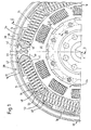
- FIG. 1 and 2 show the basic structure of an inventive Vibration damping device 10.
- This includes a Coupling to a drive shaft 12, for example a crankshaft Internal combustion engine, provided primary side 14.
- the Vibration damping device 10 one against the action of several Damper element arrangements 16 with respect to the primary side 14 by one Rotation axis A rotatable secondary side within a limited range of rotation angle 18 on.
- the secondary side 18 has a disk-like flywheel part 20, with which a schematically illustrated printing plate assembly 22 can be connected to form a friction clutch.
- the primary side 14 comprises two cover plate elements 24, 26.
- the cover plate element 24 is in its radially inner area with the drive shaft 12 can be coupled and is connected via a connecting element 28 in its radially outer area with the radially outer area of the cover plate element 26 firmly coupled. Between the cover plate elements 24, 26 is a radially outwardly limited by the connecting element 28 Space area 30 is formed, in which ultimately the damper element arrangement 16 and the damper element arrangements 16 are.
- a secondary disk-like assembly 32 is assigned to the secondary side 18 in its radially outer region with the damper element arrangements 16 cooperates and in its radially inner region with the mass part 20 connected is.
- this assembly is a generally designated 34 Idle damper arrangement integrated.
- the or each of the damper element units ultimately forming the load damper stage 16 comprises in the illustrated embodiment example a plurality of successively arranged in the circumferential direction damper springs 36 designed as helical compression springs Circumferential ends 38 of the damper element arrangements 16 arranged Damper springs 36 are supported with their ends 40 close to the circumference So-called spring plate 42 for torque or power transmission on the Primary side 14 or the secondary side 18. This is done on the secondary side Support via radially outwardly projecting arm sections 44 of the disk-like Assembly 32. This support is provided on the primary side, for example via support elements attached to the cover disk elements 24, 26 46.
- each damper element unit 16 In their ends 48 positioned facing each other, they are supported Damper springs 36 of each damper element unit 16 via so-called Slide shoes 50 from each other. Each of these slide shoes 50 has a radially outwardly facing sliding surface area 52, which on a radially inwardly positioned sliding surface 54 of the Connecting element 28 abuts. In a corresponding manner, the Spring plate 42 radially outside respective sliding surface areas 56 with which they are also supported or supported on the sliding surface 54 can be.
- the present invention now proposes measures by which Defined setting of the friction relationships between the different Sliding elements 42, 50 on the one hand and the sliding surface 54 on the other hand Vibration damping characteristic of an inventive Vibration damping device for a plurality of operating states can be optimized.
- the Vibration damping device 10 As already explained at the beginning, it is necessary on the one hand that the Vibration damping device 10 according to the invention then vibration reducing is effective when comparatively weak vibrations, however, the damping capacity of the idle damper stage 34 exceed, occur. But still a good one Vibration damping behavior is present if, for example, by Load change vibrations induced relative rotations between the Primary side 14 and the secondary side 18 occur. In the former case it is required to provide a vibration damping function even with comparatively weak vibrations Damper element assemblies 16 by compressing at least one Part of their damper springs 36 a relative rotation between the primary side 14 and the secondary side 18. That means that then rubbing sliding members 42 or 50 moving along the sliding surface 54 may only be a comparatively small one with respect to this sliding surface 54 Experience friction. It is to reduce major vibrations however advantageous, a comparatively strong frictional interaction between the sliding members 42 and 50 and the sliding surface 54 on the connecting element 28 to provide.
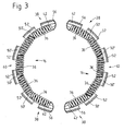
- the sliding shoes 50 ' which then immediately follow in the circumferential direction can with such at least in the area of their sliding surfaces 52 Carbon fibers or aramid fibers reinforced plastic.
- the sliding shoes 50 ′′ positioned closer to the circumferential center 60 can then again with glass fibers at least in the area of their sliding surfaces 52 reinforced base plastic, for example polyamide, be trained.
- the connector providing the sliding surface 54 28 is generally constructed of metal and also has in the the surface area providing the sliding surface 54 is a metallic one Surface on. Regarding such a metallic surface the sliding elements reinforced with carbon fiber or aramid fiber are less Coefficients of friction as the friction elements reinforced with glass fiber.
- Vibrations are then stimulated by compressing the circumferential center Damper springs 36 shift the sliding shoes 50 ", due to the significantly higher static or sliding friction coefficient with respect to the sliding surface 54, a significantly larger proportion here the vibrational energy introduced into friction work and then as Heat is dissipated.
- Damper element arrangement 16 are only those at the circumferential ends 38 positioned spring plate 42 at least in the area of their sliding surfaces 56 carbon fiber or glass fiber reinforced plastic.
- the different Sliding shoes 50 'and 50 ", which are closer to the circumferential center 60, than the spring plate 42 are then, for example, made of glass fiber reinforced Plastic and thus have with respect to the sliding surface 54th a higher coefficient of friction than that arranged in the circumferential ends 38 Spring plate 42.
- the sliding member closest to the peripheral end 38 for example the spring plate 42 is made of carbon fiber or aramid reinforced base plastic, for example polyamide, with the addition of a solid lubricant, for example, polytetrafluoroethylene (PTFE).
- PTFE polytetrafluoroethylene
- This in Circumferential direction in the direction of the circumferential center area following Sliding element, for example the next spring plate 50, is made of carbon fiber reinforced or glass fiber reinforced plastic without addition of such a solid lubricant.
- the next one then The following sliding body is then made of glass fiber reinforced Plastic with the addition of a solid lubricant, for example Plytetraflourethylene again, trained, the next then to the center
- the following sliding element is then with glass fiber reinforced plastic without the addition of an additional solid lubricant, for example Polytetrafluoroethylene, trained.
- Vibration damping device in the above Grading of various admixtures or basic body materials
- the two circumferential sliding elements that is, the spring plate 42 carbon fiber or aramid fiber reinforced plastic with the addition of a Solid lubricant build up, which then follow to the center of the circumference Sliding elements, for example in FIG. 3 the sliding shoes 50 'with carbon fiber or aramid fiber reinforced material without solid lubricant or with to train less solid lubricant admixture, and by the two the circumferential center closest to the sliding elements, i.e. the sliding shoes 50 ", one made of glass fiber reinforced plastic with or without less solid lubricant admixture and one made of glass fiber reinforced Plastic with solid lubricant admixture or with higher solid lubricant admixture build.
- the gradation of the friction characteristic from the area close to the circumference to get to the area close to the circumference it is fundamentally also possible, 54 different surface areas on the sliding surface to provide, for example by locally coating the same or by coating different areas with different materials, which then relate to the organs of the damper element arrangement which become frictionally effective 16 different static or sliding friction coefficients have as a consequence.
- the sliding surface 54 has a lower coefficient of friction on, than in the essentially with the circumferential middle Areas of the damper element arrangement 16 interacting surface areas.
- the principle of increasing the friction strength described in detail above between the area close to the circumference and the area close to the circumference is particularly beneficial when additionally in the sliding elements provided at the circumferential ends, i.e. the Spring washers 42, each provided a groove providing an angle of rotation is. So this can be a groove in which the arm-like section 44 of the Secondary side 18 comes into contact with the respective spring plate 42, so that basically a minimal free rotation angle between the primary side 14 and the secondary side 18 is possible.
- load changes i.e.
Landscapes
- Engineering & Computer Science (AREA)
- General Engineering & Computer Science (AREA)
- Physics & Mathematics (AREA)
- Acoustics & Sound (AREA)
- Aviation & Aerospace Engineering (AREA)
- Mechanical Engineering (AREA)
- Vibration Prevention Devices (AREA)
- Vibration Dampers (AREA)
- Fluid-Damping Devices (AREA)
- Motor Power Transmission Devices (AREA)
Applications Claiming Priority (2)
| Application Number | Priority Date | Filing Date | Title |
|---|---|---|---|
| DE10105688A DE10105688A1 (de) | 2001-02-08 | 2001-02-08 | Schwingungsdämpfungseinrichtung |
| DE10105688 | 2001-02-08 |
Publications (3)
| Publication Number | Publication Date |
|---|---|
| EP1231406A2 true EP1231406A2 (fr) | 2002-08-14 |
| EP1231406A3 EP1231406A3 (fr) | 2003-08-13 |
| EP1231406B1 EP1231406B1 (fr) | 2005-02-09 |
Family
ID=7673260
Family Applications (1)
| Application Number | Title | Priority Date | Filing Date |
|---|---|---|---|
| EP01129359A Expired - Lifetime EP1231406B1 (fr) | 2001-02-08 | 2001-12-17 | Dispositif d'amortissement de vibration |
Country Status (3)
| Country | Link |
|---|---|
| EP (1) | EP1231406B1 (fr) |
| AT (1) | ATE289023T1 (fr) |
| DE (2) | DE10105688A1 (fr) |
Cited By (4)
| Publication number | Priority date | Publication date | Assignee | Title |
|---|---|---|---|---|
| EP1460304A1 (fr) * | 2003-03-20 | 2004-09-22 | Hyundai Motor Company | Amortisseur d'oscillations de torsion |
| EP1626197A1 (fr) * | 2004-08-11 | 2006-02-15 | Hyundai Motor Company | Amortisseur de vibrations torsionelles |
| EP1686285A1 (fr) * | 2003-03-20 | 2006-08-02 | Hyundai Motor Company | Amortisseur d'oscillations de torsion |
| EP1826432A3 (fr) * | 2006-02-28 | 2008-04-23 | LuK Lamellen und Kupplungsbau Beteiligungs KG | Dispositif d'embrayage avec amortisseur |
Families Citing this family (2)
| Publication number | Priority date | Publication date | Assignee | Title |
|---|---|---|---|---|
| DE102007016744A1 (de) | 2007-04-07 | 2008-10-09 | Zf Friedrichshafen Ag | Torsionsschwingungsdämpfer |
| DE102017216409B4 (de) * | 2017-09-15 | 2022-01-05 | Weberit Werke Dräbing Gmbh | Kunststoffbauteil, druckfederführungselement und zweimassenschwungrad |
Citations (1)
| Publication number | Priority date | Publication date | Assignee | Title |
|---|---|---|---|---|
| DE4128868A1 (de) | 1991-08-30 | 1993-03-04 | Fichtel & Sachs Ag | Zweimassenschwungrad mit gleitschuh |
Family Cites Families (3)
| Publication number | Priority date | Publication date | Assignee | Title |
|---|---|---|---|---|
| FR2652399B1 (fr) * | 1989-09-26 | 1994-06-24 | Valeo | Dispositif amortisseur de torsion a patins de frottement, notamment pour vehicule automobile. |
| FR2663386B1 (fr) * | 1990-06-15 | 1992-09-11 | Valeo | Double volant amortisseur, notamment pour vehicule automobile. |
| DE19924213A1 (de) * | 1999-05-27 | 2000-11-30 | Mannesmann Sachs Ag | Abstützelement und dieses enthaltender Torsionsschwingungsdämpfer |
-
2001
- 2001-02-08 DE DE10105688A patent/DE10105688A1/de not_active Ceased
- 2001-12-17 EP EP01129359A patent/EP1231406B1/fr not_active Expired - Lifetime
- 2001-12-17 DE DE50105302T patent/DE50105302D1/de not_active Expired - Lifetime
- 2001-12-17 AT AT01129359T patent/ATE289023T1/de not_active IP Right Cessation
Patent Citations (1)
| Publication number | Priority date | Publication date | Assignee | Title |
|---|---|---|---|---|
| DE4128868A1 (de) | 1991-08-30 | 1993-03-04 | Fichtel & Sachs Ag | Zweimassenschwungrad mit gleitschuh |
Cited By (7)
| Publication number | Priority date | Publication date | Assignee | Title |
|---|---|---|---|---|
| EP1460304A1 (fr) * | 2003-03-20 | 2004-09-22 | Hyundai Motor Company | Amortisseur d'oscillations de torsion |
| EP1686285A1 (fr) * | 2003-03-20 | 2006-08-02 | Hyundai Motor Company | Amortisseur d'oscillations de torsion |
| US7140966B2 (en) | 2003-03-20 | 2006-11-28 | Hyundai Motor Company | Torsional vibration damper |
| US7204761B2 (en) | 2003-03-20 | 2007-04-17 | Hyundai Motor Company | Torsional vibration damper |
| EP1626197A1 (fr) * | 2004-08-11 | 2006-02-15 | Hyundai Motor Company | Amortisseur de vibrations torsionelles |
| US7426984B2 (en) | 2004-08-11 | 2008-09-23 | Hyundai Motor Company | Torsional vibration damper |
| EP1826432A3 (fr) * | 2006-02-28 | 2008-04-23 | LuK Lamellen und Kupplungsbau Beteiligungs KG | Dispositif d'embrayage avec amortisseur |
Also Published As
| Publication number | Publication date |
|---|---|
| ATE289023T1 (de) | 2005-02-15 |
| EP1231406A3 (fr) | 2003-08-13 |
| DE50105302D1 (de) | 2005-03-17 |
| DE10105688A1 (de) | 2002-08-14 |
| EP1231406B1 (fr) | 2005-02-09 |
Similar Documents
| Publication | Publication Date | Title |
|---|---|---|
| DE69221505T2 (de) | Dämpfer mit oberflächenwirkung | |
| DE69405215T2 (de) | Dämpfungseinrichtung zum ausgleichen von drehstössen und reibungskupplung mit einer derartigen vorrichtung | |
| EP1106853B1 (fr) | Embrayage avec amortisseur de torsion | |
| EP0916874B1 (fr) | Poulie découplée | |
| DE69521982T2 (de) | Zweimassenschwungrad | |
| DE10241879A1 (de) | Drehschwingungsdämpfer | |
| DE3800566A1 (de) | Daempfungseinrichtung | |
| EP0621413B1 (fr) | Accouplement élastique en rotation | |
| DE4225226A1 (de) | Riemenspannvorrichtung | |
| WO2001071219A1 (fr) | Poulie decouplee des vibrations avec amortisseur viscostatique integre | |
| DE69703930T2 (de) | Ein gerät zur isolation von drehmomentschwingungen | |
| DE4229613C2 (de) | Stützlager | |
| DE102007033164A1 (de) | Torsionsschwingungsdämpferanordnung | |
| DE2153411A1 (de) | Elastische klauenkupplung | |
| EP1462675A2 (fr) | Amortisseur de vibrations de torsion | |
| EP1231406B1 (fr) | Dispositif d'amortissement de vibration | |
| EP0472950B1 (fr) | Accouplement élastique | |
| DE102008013577B4 (de) | Torsionsschwingungsdämpfer | |
| EP0698747B1 (fr) | Accouplement élastique en rotation avec amortisseur de torsion intégré | |
| DE19531639A1 (de) | Drehschwingungsdämpfer | |
| DE102010013632A1 (de) | Kupplungsscheibe | |
| DE19924213A1 (de) | Abstützelement und dieses enthaltender Torsionsschwingungsdämpfer | |
| EP1235989A1 (fr) | Palier pour levier pivotant | |
| EP1598574B1 (fr) | Eléments d'appui | |
| DE3218955A1 (de) | Daempfungsscheibe |
Legal Events
| Date | Code | Title | Description |
|---|---|---|---|
| PUAI | Public reference made under article 153(3) epc to a published international application that has entered the european phase |
Free format text: ORIGINAL CODE: 0009012 |
|
| AK | Designated contracting states |
Kind code of ref document: A2 Designated state(s): AT BE CH CY DE DK ES FI FR GB GR IE IT LI LU MC NL PT SE TR |
|
| AX | Request for extension of the european patent |
Free format text: AL;LT;LV;MK;RO;SI |
|
| PUAL | Search report despatched |
Free format text: ORIGINAL CODE: 0009013 |
|
| AK | Designated contracting states |
Designated state(s): AT BE CH CY DE DK ES FI FR GB GR IE IT LI LU MC NL PT SE TR |
|
| AX | Request for extension of the european patent |
Extension state: AL LT LV MK RO SI |
|
| 17P | Request for examination filed |
Effective date: 20030711 |
|
| 17Q | First examination report despatched |
Effective date: 20030916 |
|
| AKX | Designation fees paid |
Designated state(s): AT BE CH CY DE DK ES FI FR GB GR IE IT LI LU MC NL PT SE TR |
|
| GRAP | Despatch of communication of intention to grant a patent |
Free format text: ORIGINAL CODE: EPIDOSNIGR1 |
|
| GRAS | Grant fee paid |
Free format text: ORIGINAL CODE: EPIDOSNIGR3 |
|
| GRAA | (expected) grant |
Free format text: ORIGINAL CODE: 0009210 |
|
| AK | Designated contracting states |
Kind code of ref document: B1 Designated state(s): AT BE CH CY DE DK ES FI FR GB GR IE IT LI LU MC NL PT SE TR |
|
| PG25 | Lapsed in a contracting state [announced via postgrant information from national office to epo] |
Ref country code: IT Free format text: LAPSE BECAUSE OF FAILURE TO SUBMIT A TRANSLATION OF THE DESCRIPTION OR TO PAY THE FEE WITHIN THE PRESCRIBED TIME-LIMIT;WARNING: LAPSES OF ITALIAN PATENTS WITH EFFECTIVE DATE BEFORE 2007 MAY HAVE OCCURRED AT ANY TIME BEFORE 2007. THE CORRECT EFFECTIVE DATE MAY BE DIFFERENT FROM THE ONE RECORDED. Effective date: 20050209 Ref country code: TR Free format text: LAPSE BECAUSE OF FAILURE TO SUBMIT A TRANSLATION OF THE DESCRIPTION OR TO PAY THE FEE WITHIN THE PRESCRIBED TIME-LIMIT Effective date: 20050209 Ref country code: NL Free format text: LAPSE BECAUSE OF FAILURE TO SUBMIT A TRANSLATION OF THE DESCRIPTION OR TO PAY THE FEE WITHIN THE PRESCRIBED TIME-LIMIT Effective date: 20050209 Ref country code: FI Free format text: LAPSE BECAUSE OF FAILURE TO SUBMIT A TRANSLATION OF THE DESCRIPTION OR TO PAY THE FEE WITHIN THE PRESCRIBED TIME-LIMIT Effective date: 20050209 Ref country code: IE Free format text: LAPSE BECAUSE OF FAILURE TO SUBMIT A TRANSLATION OF THE DESCRIPTION OR TO PAY THE FEE WITHIN THE PRESCRIBED TIME-LIMIT Effective date: 20050209 |
|
| REG | Reference to a national code |
Ref country code: GB Ref legal event code: FG4D Free format text: NOT ENGLISH |
|
| REG | Reference to a national code |
Ref country code: CH Ref legal event code: EP |
|
| REG | Reference to a national code |
Ref country code: IE Ref legal event code: FG4D Free format text: GERMAN |
|
| REF | Corresponds to: |
Ref document number: 50105302 Country of ref document: DE Date of ref document: 20050317 Kind code of ref document: P |
|
| PG25 | Lapsed in a contracting state [announced via postgrant information from national office to epo] |
Ref country code: DK Free format text: LAPSE BECAUSE OF FAILURE TO SUBMIT A TRANSLATION OF THE DESCRIPTION OR TO PAY THE FEE WITHIN THE PRESCRIBED TIME-LIMIT Effective date: 20050509 Ref country code: SE Free format text: LAPSE BECAUSE OF FAILURE TO SUBMIT A TRANSLATION OF THE DESCRIPTION OR TO PAY THE FEE WITHIN THE PRESCRIBED TIME-LIMIT Effective date: 20050509 Ref country code: GR Free format text: LAPSE BECAUSE OF FAILURE TO SUBMIT A TRANSLATION OF THE DESCRIPTION OR TO PAY THE FEE WITHIN THE PRESCRIBED TIME-LIMIT Effective date: 20050509 |
|
| GBT | Gb: translation of ep patent filed (gb section 77(6)(a)/1977) |
Effective date: 20050421 |
|
| PG25 | Lapsed in a contracting state [announced via postgrant information from national office to epo] |
Ref country code: ES Free format text: LAPSE BECAUSE OF FAILURE TO SUBMIT A TRANSLATION OF THE DESCRIPTION OR TO PAY THE FEE WITHIN THE PRESCRIBED TIME-LIMIT Effective date: 20050520 |
|
| NLV1 | Nl: lapsed or annulled due to failure to fulfill the requirements of art. 29p and 29m of the patents act | ||
| REG | Reference to a national code |
Ref country code: IE Ref legal event code: FD4D |
|
| PLBE | No opposition filed within time limit |
Free format text: ORIGINAL CODE: 0009261 |
|
| STAA | Information on the status of an ep patent application or granted ep patent |
Free format text: STATUS: NO OPPOSITION FILED WITHIN TIME LIMIT |
|
| PG25 | Lapsed in a contracting state [announced via postgrant information from national office to epo] |
Ref country code: AT Free format text: LAPSE BECAUSE OF NON-PAYMENT OF DUE FEES Effective date: 20051217 Ref country code: CY Free format text: LAPSE BECAUSE OF FAILURE TO SUBMIT A TRANSLATION OF THE DESCRIPTION OR TO PAY THE FEE WITHIN THE PRESCRIBED TIME-LIMIT Effective date: 20051217 |
|
| ET | Fr: translation filed | ||
| PG25 | Lapsed in a contracting state [announced via postgrant information from national office to epo] |
Ref country code: LU Free format text: LAPSE BECAUSE OF NON-PAYMENT OF DUE FEES Effective date: 20051231 Ref country code: MC Free format text: LAPSE BECAUSE OF NON-PAYMENT OF DUE FEES Effective date: 20051231 Ref country code: BE Free format text: LAPSE BECAUSE OF NON-PAYMENT OF DUE FEES Effective date: 20051231 Ref country code: CH Free format text: LAPSE BECAUSE OF NON-PAYMENT OF DUE FEES Effective date: 20051231 Ref country code: LI Free format text: LAPSE BECAUSE OF NON-PAYMENT OF DUE FEES Effective date: 20051231 |
|
| 26N | No opposition filed |
Effective date: 20051110 |
|
| REG | Reference to a national code |
Ref country code: CH Ref legal event code: PL |
|
| BERE | Be: lapsed |
Owner name: ZF SACHS A.G. Effective date: 20051231 |
|
| PG25 | Lapsed in a contracting state [announced via postgrant information from national office to epo] |
Ref country code: PT Free format text: LAPSE BECAUSE OF NON-PAYMENT OF DUE FEES Effective date: 20050709 |
|
| PGFP | Annual fee paid to national office [announced via postgrant information from national office to epo] |
Ref country code: GB Payment date: 20081217 Year of fee payment: 8 |
|
| GBPC | Gb: european patent ceased through non-payment of renewal fee |
Effective date: 20091217 |
|
| PG25 | Lapsed in a contracting state [announced via postgrant information from national office to epo] |
Ref country code: GB Free format text: LAPSE BECAUSE OF NON-PAYMENT OF DUE FEES Effective date: 20091217 |
|
| PGFP | Annual fee paid to national office [announced via postgrant information from national office to epo] |
Ref country code: DE Payment date: 20121213 Year of fee payment: 12 |
|
| PGFP | Annual fee paid to national office [announced via postgrant information from national office to epo] |
Ref country code: FR Payment date: 20130107 Year of fee payment: 12 |
|
| REG | Reference to a national code |
Ref country code: DE Ref legal event code: R081 Ref document number: 50105302 Country of ref document: DE Owner name: ZF FRIEDRICHSHAFEN AG, DE Free format text: FORMER OWNER: ZF SACHS AG, 97424 SCHWEINFURT, DE Effective date: 20130326 |
|
| REG | Reference to a national code |
Ref country code: DE Ref legal event code: R119 Ref document number: 50105302 Country of ref document: DE |
|
| REG | Reference to a national code |
Ref country code: FR Ref legal event code: ST Effective date: 20140829 |
|
| REG | Reference to a national code |
Ref country code: DE Ref legal event code: R119 Ref document number: 50105302 Country of ref document: DE Effective date: 20140701 |
|
| PG25 | Lapsed in a contracting state [announced via postgrant information from national office to epo] |
Ref country code: DE Free format text: LAPSE BECAUSE OF NON-PAYMENT OF DUE FEES Effective date: 20140701 |
|
| PG25 | Lapsed in a contracting state [announced via postgrant information from national office to epo] |
Ref country code: FR Free format text: LAPSE BECAUSE OF NON-PAYMENT OF DUE FEES Effective date: 20131231 |