EP1231434A2 - Verfahren zum Verbrennen von schwer verbrennbaren Materialen - Google Patents
Verfahren zum Verbrennen von schwer verbrennbaren Materialen Download PDFInfo
- Publication number
- EP1231434A2 EP1231434A2 EP02001639A EP02001639A EP1231434A2 EP 1231434 A2 EP1231434 A2 EP 1231434A2 EP 02001639 A EP02001639 A EP 02001639A EP 02001639 A EP02001639 A EP 02001639A EP 1231434 A2 EP1231434 A2 EP 1231434A2
- Authority
- EP
- European Patent Office
- Prior art keywords
- air
- combustion chamber
- ionized
- combustion
- control device
- Prior art date
- Legal status (The legal status is an assumption and is not a legal conclusion. Google has not performed a legal analysis and makes no representation as to the accuracy of the status listed.)
- Granted
Links
Images

Classifications
-
- F—MECHANICAL ENGINEERING; LIGHTING; HEATING; WEAPONS; BLASTING
- F27—FURNACES; KILNS; OVENS; RETORTS
- F27B—FURNACES, KILNS, OVENS OR RETORTS IN GENERAL; OPEN SINTERING OR LIKE APPARATUS
- F27B17/00—Furnaces of a kind not covered by any of groups F27B1/00 - F27B15/00
-
- B—PERFORMING OPERATIONS; TRANSPORTING
- B22—CASTING; POWDER METALLURGY
- B22C—FOUNDRY MOULDING
- B22C9/00—Moulds or cores; Moulding processes
- B22C9/02—Sand moulds or like moulds for shaped castings
- B22C9/04—Use of lost patterns
- B22C9/043—Removing the consumable pattern
Definitions
- the invention relates to a method for burning of flame-retardant material, the material in a combustion chamber of a burnout furnace with feed is burned by air.
- the invention also relates a device for burning combustible Material according to the preamble of claim 9.
- Models in wax or sintered are used in the furnace Parts embedded in plaster, sand or ceramic melted out at a high temperature and the remaining Rest with an even higher temperature (above 600 ° C burned. This happens through the combustion with air in a chemical reaction.
- Such burnout furnace are, for example, in the Used in the jewelry industry or in foundry needs, where wax and cast resin bound materials, which in Sand, ceramics or plaster are embedded, burned out become.
- the present invention is based on the object a method and an apparatus for burning difficult to burn material by means of a burn-out furnace to create an almost smoke - free and residue-free combustion of the material, if possible at low temperatures, preferably in short Firing cycles should be achieved.
- this object is achieved in that the air supplied to the combustion chamber of the burnout furnace is ionized.
- Ionization converts oxygen molecules (O 2 ) into an ion, which creates ozone (O 3 ).
- the ozone formed is an unstable ion and is very quickly split into the molecule (O 2 ) and the atom (O).
- the ozone is an aggressive gas that is very quickly disassembled.
- the released O-atom connects with other O atoms to form an oxygen molecule.
- the O atoms prefer a chemical reaction with foreign material, especially carbon (C) and carbon monoxide (CO). This creates a compulsion for complete combustion.
- the difficultly combustible lead in an advantageous manner Materials are forced to a chemical Reaction.
- the result is clean combustion without smoke in the form and in the Combustion chamber.
- the firing results are residue-free and only need a low energy consumption.
- carbon precipitation or Deposits in the combustion chamber avoided. thats why no closed heating coil necessary and it can an open heating coil can be used.
- the Method according to the invention all known 3D models made of polystyrene, polystyrene (SLS), STL materials, Thermopolymers and even those infiltrated with wax or resin Starch / cellulose for metal investment casting directly embedded in plaster, ceramic or sand and at Temperatures around 600 ° C are burned out without residue.
- each difficult to burn material at low temperatures can be burned out smoke-free from a maximum of 650 ° C.
- inventive method and the inventive Prototype can be made of metal inexpensively and in a particularly simple manner of excellent quality.
- the inventive method and the inventive Device can be particularly advantageous can be used for the well-known 3D inkjet process.
- the models created by the 3D inkjet process can be used for model investment casting directly in plaster molds be embedded. Pass through these procedures the models made of flame retardant, with wax or Resin infiltrated starch / cellulose. After extensive and lengthy trials at different temperatures the models were completely successful in the mold at low temperatures of maximum 650 ° C to burn smoke-free.
- the possibility of the models Made of starch material, smoke-free and without residues burnout reduces lead times and improves the quality of the parts considerably.
- the air flow control device By the air flow control device, the conditioned air is controlled in the combustion chamber of the Bring the burnout furnace.
- the Air before being fed into the combustion chamber by means of a Air ionization device is ionized.
- Air ionization device The ionization of the air by a known principle Air ionization device has been in trials turned out to be particularly suitable and inexpensive.
- the inventive method and the inventive Device are based on the in the first and 2 illustrated principle explained in principle, however, are not limited to this.
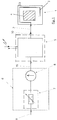
- the one in Fig. 1 Burnout furnace 1 shown is particularly suitable for the production of prototypes from metal.
- the stake such a burnout furnace 1 or the burnout However, difficult to burn material various other, obvious to the expert Reasons.
- Burnout furnaces can be of different designs, for example as a chamber, slide-in car or hood oven be trained.
- the burnout furnace 1 as shown in FIG. 1, ionized air supplied through an air inlet 2, those in the combustion chamber of the burnout furnace 1 for one complete and smoke-free combustion of the heavy combustible material leads.
- the ionized Air through a heat exchanger 3 below Tool 4 blown in.
- the tool 4 is the expert common and therefore not shown in detail.
- an air ionization device 5 Through the air ionization device 5 the air ionization device 5 is supplied Air is converted from the molecular to the ionic state. Then the ionized air enters the air 2 of the burnout furnace 1 supplied.
- Fig. 1 is an air flow control device 6 for the metered supply of Air provided. It can thus be done in a simple manner the amount of fuel fed into the combustion chamber Air ionization device 5 Check ionized air. The combustion in the burnout furnace 1 or the combustion chamber can be controlled by the air flow control device 6 or the supplied ionized air Taxes.
- the air flow control device 6 in the direction of flow Air arranged so that the air flow control device 6 in front of the air ionization device 5 happens.
- the air flow control device 6 can also between the air ionization device 5 and the Burnout furnace 1 may be arranged.
- the Air flow control device 6 with an air pressure regulator 7 and a flow indicator 8 is formed.
- the compressed air is controlled by the air pressure regulator 7, which can also be called a maintenance unit, controlled or regulated.
- the air pressure regulator 7 will through an air pressure regulator input 9 with compressed air provided.
- the air ionizer 5 for conversion of oxygen from the air in ozone a component of the burnout furnace 1.
- the air flow control device 6, the combustion chamber, and the air ionization device 5 components of the burn-out furnace 1.
- the use of the air ionization device is particularly advantageous 5 with the air flow control device 6, which the air flow into the burnout furnace 1 controlled and thus a smoke-free and residue-free Burn the material in a particularly suitable way Way.
- the air ionization device 5 for ionizing the Air and the air flow control device 6 can as separate from the burnout furnace 1 or the combustion chamber and thus connectable unit are formed. This ensures that this unit to everyone Burnout furnace 1 can be connected or retrofitted can. By burning residual gases and vapors this system also serves as a catalyst.
- the combustion chamber also be designed as a gas furnace. The combustion process in the combustion chamber is complete Combustion carried out.
- Fig. 2 shows an air ionization device known in principle 5.
- the air ionization device 5 consists of a safety switch 10, one Current control unit 11, a high voltage transformer 12, an air pressure vessel 13, ionizing plates 14 and an air inlet 15 and an air outlet 16. Since such air ionization devices 5 in principle are known, this will not be discussed in more detail.
Landscapes
- Engineering & Computer Science (AREA)
- Mechanical Engineering (AREA)
- General Engineering & Computer Science (AREA)
- Incineration Of Waste (AREA)
- Air Supply (AREA)
- Glass Compositions (AREA)
- Processing Of Solid Wastes (AREA)
- Solid-Fuel Combustion (AREA)
Abstract
Description
- Fig. 1
- eine schematische Darstellung eines Ausbrennofens, einer Luftionisierungseinrichtung und einer Luftdurchflußregeleinrichtung; und
- Fig. 2
- eine Luftdurchflußregeleinrichtung gemäß Fig. 1 im Detail.
Claims (16)
- Verfahren zum Verbrennen von schwer verbrennbarem Material, wobei das Material in einer Brennkammer eines Ausbrennofens unter Zufuhr von Luft verbrannt wird,
dadurch gekennzeichnet, daß
die der Brennkammer des Ausbrennofens (1) zugeführte Luft ionisiert wird. - Verfahren nach Anspruch 1,
dadurch gekennzeichnet, daß
die Luft vor der Zufuhr in die Brennkammer mittels einer Luftionisierungseinrichtung (5) ionisiert wird. - Verfahren nach Anspruch 1 oder 2,
dadurch gekennzeichnet, daß
die Menge der der Brennkammer zugeführten, ionisierten Luft mittels einer Luftzufuhrregeleinrichtung (6) kontrolliert wird. - Verfahren nach Anspruch 1, 2 oder 3
dadurch gekennzeichnet, daß
die ionisierte Luft von außen in die vorzugsweise als elektrische Brennkammer ausgebildete Brennkammer geführt wird. - Verfahren nach Anspruch 2, 3 oder 4,
dadurch gekennzeichnet, daß
durch die Luftionisierungseinrichtung (5) Sauerstoff aus der Luft in Ozon umgewandelt wird. - Verfahren nach einem der Ansprüche 1 bis 5,
dadurch gekennzeichnet, daß
die Verbrennnung in der Brennkammer durch die zugeführte Menge an ionisierter Luft gesteuert wird. - Verfahren nach einem der Ansprüche 1 bis 6,
dadurch gekennzeichnet, daß
die Verbrennung in der Brennkammer bis zur vollständigen Verbrennung des zu verbrennenden Materiales durchgeführt wird. - Verfahren nach einem der Ansprüche 1 bis 7,
dadurch gekennzeichnet, daß
die Verbrennung mit einer niedrigen Temperatur von maximal annähernd 650 °C, vorzugsweise 600 °C, erfolgt. - Vorrichtung zur Verbrennung von schwer verbrennbarem Material, insbesondere zur Herstellung von Prototypen aus Metall, mit einem Ausbrennofen, der eine Brennkammer mit einem Lufteingang aufweist, durch die Luft in die Brennkammer einbringbar ist,
dadurch gekennzeichnet, daß
die in die Brennkammer des Ausbrennofens (1) einbringbare Luft ionisiert ist. - Vorrichtung nach Anspruch 9,
dadurch gekennzeichnet, daß
vor dem Lufteingang (2) der Brennkammer eine Luftionisierungseinrichtung (5) angeordnet ist. - Vorrichtung nach Anspruch 9 oder 10,
dadurch gekennzeichnet, daß
eine Luftdurchflußregeleinrichtung (6) zur dosierten Zufuhr von Luft vorgesehen ist. - Vorrichtung nach Anspruch 10 und 11,
dadurch gekennzeichnet, daß
die Luftdurchflußregeleinrichtung (6) in Strömungsrichtung der Luft bzw. der ionisierten Luft vor oder hinter der Luftionisierungseinrichtung (5) angeordnet ist. - Vorrichtung nach Anspruch 11 oder 12,
dadurch gekennzeichnet, daß
die Luftdurchflußregeleinrichtung (6) einen Luftdruckregler (7) und einen Durchflußanzeiger (8) aufweist. - Vorrichtung nach einem der Ansprüche 9 bis 13,
dadurch gekennzeichnet, daß
die von der Luftionisierungseinrichtung (5) ionisierte Luft durch einen Wärmetauscher (3) in den Ausbrennofen (1) bzw. die Brennkammer einblasbar ist. - Vorrichtung nach einem der Ansprüche 9 bis 14,
dadurch gekennzeichnet, daß
die Luftionisierungseinrichtung (5) zur Ionisierung der Luft und die Luftdurchflußregeleinrichtung (6) als von dem Ausbrennofen (1) bzw. der Brennkammer separate und damit verbindbare Einheit ausgebildet ist. - Vorrichtung nach einem der Ansprüche 9 bis 14,
dadurch gekennzeichnet, daß
die Luftionisierungseinrichtung (5) zur Ionisierung der Luft, die elektrische Brennkammer sowie die Luftdurchflußregeleinrichtung (6) als Bestandteile des Ausbrennofens (1) ausgebildet sind
Applications Claiming Priority (2)
| Application Number | Priority Date | Filing Date | Title |
|---|---|---|---|
| DE20102129U | 2001-02-07 | ||
| DE20102129U DE20102129U1 (de) | 2001-02-07 | 2001-02-07 | Ausbrennofen für schwer verbrennbare Materialien |
Publications (3)
| Publication Number | Publication Date |
|---|---|
| EP1231434A2 true EP1231434A2 (de) | 2002-08-14 |
| EP1231434A3 EP1231434A3 (de) | 2002-12-04 |
| EP1231434B1 EP1231434B1 (de) | 2007-10-31 |
Family
ID=7952652
Family Applications (1)
| Application Number | Title | Priority Date | Filing Date |
|---|---|---|---|
| EP02001639A Expired - Lifetime EP1231434B1 (de) | 2001-02-07 | 2002-01-24 | Verfahren zum Verbrennen von schwer verbrennbaren Materialen |
Country Status (3)
| Country | Link |
|---|---|
| EP (1) | EP1231434B1 (de) |
| AT (1) | ATE377173T1 (de) |
| DE (2) | DE20102129U1 (de) |
Cited By (1)
| Publication number | Priority date | Publication date | Assignee | Title |
|---|---|---|---|---|
| DE102006045946A1 (de) * | 2006-09-28 | 2008-04-03 | Wjatscheslaw Boguslajew | Verbrennungskammer, die ein äußeres Gehäuse, ein Flammrohr, Kraftstoffdüsen, eine Zündkerze und Ionisierungskammer mit darin aufgestellten Elektroden enthält und sich dadurch kennzeichnet, daß ihre Ionisierungskammer mit Drehbarkeit ausgeführt ist |
Families Citing this family (1)
| Publication number | Priority date | Publication date | Assignee | Title |
|---|---|---|---|---|
| DE102019005630B3 (de) * | 2019-08-12 | 2021-02-18 | Günter Vogel | Ionisierungsvorrichtung und Verfahren zur Ionisierung eines Gases |
Family Cites Families (5)
| Publication number | Priority date | Publication date | Assignee | Title |
|---|---|---|---|---|
| US3495555A (en) * | 1968-02-23 | 1970-02-17 | Washington Incinerator Sales & | Plastics incinerator |
| US3768424A (en) * | 1972-01-07 | 1973-10-30 | Mechtron Int Corp | Apparatus and method for the pyrolysis of solid waste material |
| DE2908912A1 (de) * | 1979-03-07 | 1980-09-18 | Mueller Otto Gmbh | Vorrichtung zum entfernen von organischen gasen oder daempfen aus rohgasen, insbesondere abluft |
| JPS57192721A (en) * | 1981-05-24 | 1982-11-26 | Yukiya Sato | Ionizing device of air for combustion furnace |
| US5924502A (en) * | 1996-11-12 | 1999-07-20 | Dresser Industries, Inc. | Steel-bodied bit |
-
2001
- 2001-02-07 DE DE20102129U patent/DE20102129U1/de not_active Expired - Lifetime
-
2002
- 2002-01-24 AT AT02001639T patent/ATE377173T1/de not_active IP Right Cessation
- 2002-01-24 DE DE50211124T patent/DE50211124D1/de not_active Expired - Fee Related
- 2002-01-24 EP EP02001639A patent/EP1231434B1/de not_active Expired - Lifetime
Cited By (2)
| Publication number | Priority date | Publication date | Assignee | Title |
|---|---|---|---|---|
| DE102006045946A1 (de) * | 2006-09-28 | 2008-04-03 | Wjatscheslaw Boguslajew | Verbrennungskammer, die ein äußeres Gehäuse, ein Flammrohr, Kraftstoffdüsen, eine Zündkerze und Ionisierungskammer mit darin aufgestellten Elektroden enthält und sich dadurch kennzeichnet, daß ihre Ionisierungskammer mit Drehbarkeit ausgeführt ist |
| DE102006045946B4 (de) * | 2006-09-28 | 2008-11-06 | Wjatscheslaw Boguslajew | Verbrennungskammer, die ein äußeres Gehäuse, ein Flammrohr, Kraftstoffdüsen, eine Zündkerze und Ionisierungskammer mit darin aufgestellten Elektroden enthält und sich dadurch kennzeichnet, daß ihre Ionisierungskammer mit Drehbarkeit ausgeführt ist |
Also Published As
| Publication number | Publication date |
|---|---|
| DE20102129U1 (de) | 2001-06-13 |
| ATE377173T1 (de) | 2007-11-15 |
| DE50211124D1 (de) | 2007-12-13 |
| EP1231434B1 (de) | 2007-10-31 |
| EP1231434A3 (de) | 2002-12-04 |
Similar Documents
| Publication | Publication Date | Title |
|---|---|---|
| DE3121860C2 (de) | Verfahren zum Vorwärmen von Stahlschrott mittels des Abgases aus einem Stahlerzeugungs-Elektroofen | |
| DE69903365T2 (de) | Verfahren und Vorrichtung zum Aufheizen einer Vorrichtung für das Läutern von geschmolzenem Glas unter vermindertem Druck | |
| EP1231434B1 (de) | Verfahren zum Verbrennen von schwer verbrennbaren Materialen | |
| DE3027753A1 (de) | Verbrennungsvorrichtung, insbesondere zur durchfuehrung des thermischen regenerativverfahrens | |
| DE1906209B2 (de) | Verfahren zur Herstellung keramischer Erzeugnisse und Vorrichtung zur Durchführung des Verfahrens | |
| DE2134749C3 (de) | Brenner | |
| WO2023173152A1 (de) | Verbrennungsofenanlage | |
| DE2400700B1 (de) | Verfahren und Einrichtung zur Beseitigung von Abgasen von mit kunstharzgebundenen Sanden hergestellten Gießformen | |
| EP1566256A1 (de) | Verfahren und Vorrichtung zur Reinigung eines Blaskopfes für Kunststofffolien | |
| DE1458174C3 (de) | Verfahren zur Herstellung von Metallpulver oder -granulat durch Verdüsen | |
| EP0393554A2 (de) | Verfahren zum Berussen von Flächen von Gegenständen mit einem Brenner | |
| DE102011050264B4 (de) | Vorrichtung zum Begasen von Gusskernen | |
| WO1999026019A1 (de) | Brennkammerherstellungsverfahren sowie hiernach gefertigte brennkammer eines fahrzeug-heizgeräts | |
| EP1512472A2 (de) | Verfahren und Vorrichtung zur Herstellung von Formen oder Kernen | |
| DE1758530C (de) | Vorrichtung zur Herstellung von Sand formen oder Kernen fur Gießereizwecke | |
| DE1646496C3 (de) | Verfahren und Vorrichtung zur Herstellung von Blähton und Blähschiefer | |
| DE3012338C2 (de) | Abfackeleinrichtung für einen Industrieofen zum Aufkohlen von metallischen Gegenständen | |
| DE3725587A1 (de) | Vorrichtung zur reinigung von teilchenfiltern, insbesondere russfiltern von dieselmotoren | |
| DE3941371A1 (de) | Verfahren zum zuenden eines brenners fuer die materialbearbeitung | |
| DE2616776C2 (de) | Verfahren zum Beheizen von Ziegeleiofen, insbesondere Tunnelofen | |
| DE3516058C2 (de) | Tunnelofen zum Brennen von keramischen Rohlingen und Verfahren zum Betrieb eines solchen Tunnelofens | |
| DE2522739B2 (de) | Anlage zum Verbrennen von nicht mehr erneuerbaren Fahrzeugreifen aus Gummi u.dgl | |
| DE331577C (de) | Verfahren und Vorrichtung zur Erzeugung heisser Luft mittels Feuergase fuer Trockenanlagen | |
| DE192397C (de) | ||
| DE333676C (de) | Wassergaserzeuger mit unmittelbarer Anwendung des Gases zur Beheizung |
Legal Events
| Date | Code | Title | Description |
|---|---|---|---|
| PUAI | Public reference made under article 153(3) epc to a published international application that has entered the european phase |
Free format text: ORIGINAL CODE: 0009012 |
|
| AK | Designated contracting states |
Kind code of ref document: A2 Designated state(s): AT BE CH CY DE DK ES FI FR GB GR IE IT LI LU MC NL PT SE TR |
|
| AX | Request for extension of the european patent |
Free format text: AL;LT;LV;MK;RO;SI |
|
| PUAL | Search report despatched |
Free format text: ORIGINAL CODE: 0009013 |
|
| AK | Designated contracting states |
Kind code of ref document: A3 Designated state(s): AT BE CH CY DE DK ES FI FR GB GR IE IT LI LU MC NL PT SE TR |
|
| AX | Request for extension of the european patent |
Free format text: AL;LT;LV;MK;RO;SI |
|
| 17P | Request for examination filed |
Effective date: 20030531 |
|
| AKX | Designation fees paid |
Designated state(s): AT BE CH CY DE DK ES FI FR GB GR IE IT LI LU MC NL PT SE TR |
|
| 17Q | First examination report despatched |
Effective date: 20060316 |
|
| GRAP | Despatch of communication of intention to grant a patent |
Free format text: ORIGINAL CODE: EPIDOSNIGR1 |
|
| GRAS | Grant fee paid |
Free format text: ORIGINAL CODE: EPIDOSNIGR3 |
|
| GRAA | (expected) grant |
Free format text: ORIGINAL CODE: 0009210 |
|
| AK | Designated contracting states |
Kind code of ref document: B1 Designated state(s): AT BE CH CY DE DK ES FI FR GB GR IE IT LI LU MC NL PT SE TR |
|
| REG | Reference to a national code |
Ref country code: GB Ref legal event code: FG4D Free format text: NOT ENGLISH |
|
| REG | Reference to a national code |
Ref country code: IE Ref legal event code: FG4D Free format text: LANGUAGE OF EP DOCUMENT: GERMAN |
|
| REG | Reference to a national code |
Ref country code: CH Ref legal event code: EP |
|
| REF | Corresponds to: |
Ref document number: 50211124 Country of ref document: DE Date of ref document: 20071213 Kind code of ref document: P |
|
| NLV1 | Nl: lapsed or annulled due to failure to fulfill the requirements of art. 29p and 29m of the patents act | ||
| PG25 | Lapsed in a contracting state [announced via postgrant information from national office to epo] |
Ref country code: SE Free format text: LAPSE BECAUSE OF FAILURE TO SUBMIT A TRANSLATION OF THE DESCRIPTION OR TO PAY THE FEE WITHIN THE PRESCRIBED TIME-LIMIT Effective date: 20080131 Ref country code: ES Free format text: LAPSE BECAUSE OF FAILURE TO SUBMIT A TRANSLATION OF THE DESCRIPTION OR TO PAY THE FEE WITHIN THE PRESCRIBED TIME-LIMIT Effective date: 20080211 Ref country code: NL Free format text: LAPSE BECAUSE OF FAILURE TO SUBMIT A TRANSLATION OF THE DESCRIPTION OR TO PAY THE FEE WITHIN THE PRESCRIBED TIME-LIMIT Effective date: 20071031 |
|
| GBV | Gb: ep patent (uk) treated as always having been void in accordance with gb section 77(7)/1977 [no translation filed] | ||
| PG25 | Lapsed in a contracting state [announced via postgrant information from national office to epo] |
Ref country code: PT Free format text: LAPSE BECAUSE OF FAILURE TO SUBMIT A TRANSLATION OF THE DESCRIPTION OR TO PAY THE FEE WITHIN THE PRESCRIBED TIME-LIMIT Effective date: 20080331 |
|
| REG | Reference to a national code |
Ref country code: IE Ref legal event code: FD4D |
|
| BERE | Be: lapsed |
Owner name: AHMAD, MAZOURI, DIPL.-ING. (FH) Effective date: 20080131 |
|
| PG25 | Lapsed in a contracting state [announced via postgrant information from national office to epo] |
Ref country code: DK Free format text: LAPSE BECAUSE OF FAILURE TO SUBMIT A TRANSLATION OF THE DESCRIPTION OR TO PAY THE FEE WITHIN THE PRESCRIBED TIME-LIMIT Effective date: 20071031 |
|
| EN | Fr: translation not filed | ||
| PG25 | Lapsed in a contracting state [announced via postgrant information from national office to epo] |
Ref country code: MC Free format text: LAPSE BECAUSE OF NON-PAYMENT OF DUE FEES Effective date: 20080131 |
|
| REG | Reference to a national code |
Ref country code: CH Ref legal event code: PL |
|
| PLBE | No opposition filed within time limit |
Free format text: ORIGINAL CODE: 0009261 |
|
| STAA | Information on the status of an ep patent application or granted ep patent |
Free format text: STATUS: NO OPPOSITION FILED WITHIN TIME LIMIT |
|
| 26N | No opposition filed |
Effective date: 20080801 |
|
| PG25 | Lapsed in a contracting state [announced via postgrant information from national office to epo] |
Ref country code: DE Free format text: LAPSE BECAUSE OF NON-PAYMENT OF DUE FEES Effective date: 20080801 Ref country code: CH Free format text: LAPSE BECAUSE OF NON-PAYMENT OF DUE FEES Effective date: 20080131 Ref country code: LI Free format text: LAPSE BECAUSE OF NON-PAYMENT OF DUE FEES Effective date: 20080131 Ref country code: IE Free format text: LAPSE BECAUSE OF FAILURE TO SUBMIT A TRANSLATION OF THE DESCRIPTION OR TO PAY THE FEE WITHIN THE PRESCRIBED TIME-LIMIT Effective date: 20071031 Ref country code: FR Free format text: LAPSE BECAUSE OF FAILURE TO SUBMIT A TRANSLATION OF THE DESCRIPTION OR TO PAY THE FEE WITHIN THE PRESCRIBED TIME-LIMIT Effective date: 20080704 |
|
| PG25 | Lapsed in a contracting state [announced via postgrant information from national office to epo] |
Ref country code: GB Free format text: LAPSE BECAUSE OF FAILURE TO SUBMIT A TRANSLATION OF THE DESCRIPTION OR TO PAY THE FEE WITHIN THE PRESCRIBED TIME-LIMIT Effective date: 20071031 |
|
| PG25 | Lapsed in a contracting state [announced via postgrant information from national office to epo] |
Ref country code: GR Free format text: LAPSE BECAUSE OF FAILURE TO SUBMIT A TRANSLATION OF THE DESCRIPTION OR TO PAY THE FEE WITHIN THE PRESCRIBED TIME-LIMIT Effective date: 20080201 |
|
| PG25 | Lapsed in a contracting state [announced via postgrant information from national office to epo] |
Ref country code: FI Free format text: LAPSE BECAUSE OF FAILURE TO SUBMIT A TRANSLATION OF THE DESCRIPTION OR TO PAY THE FEE WITHIN THE PRESCRIBED TIME-LIMIT Effective date: 20071031 Ref country code: BE Free format text: LAPSE BECAUSE OF NON-PAYMENT OF DUE FEES Effective date: 20080131 |
|
| PG25 | Lapsed in a contracting state [announced via postgrant information from national office to epo] |
Ref country code: AT Free format text: LAPSE BECAUSE OF NON-PAYMENT OF DUE FEES Effective date: 20080124 |
|
| PG25 | Lapsed in a contracting state [announced via postgrant information from national office to epo] |
Ref country code: CY Free format text: LAPSE BECAUSE OF FAILURE TO SUBMIT A TRANSLATION OF THE DESCRIPTION OR TO PAY THE FEE WITHIN THE PRESCRIBED TIME-LIMIT Effective date: 20071031 |
|
| PG25 | Lapsed in a contracting state [announced via postgrant information from national office to epo] |
Ref country code: LU Free format text: LAPSE BECAUSE OF NON-PAYMENT OF DUE FEES Effective date: 20080124 |
|
| PG25 | Lapsed in a contracting state [announced via postgrant information from national office to epo] |
Ref country code: TR Free format text: LAPSE BECAUSE OF FAILURE TO SUBMIT A TRANSLATION OF THE DESCRIPTION OR TO PAY THE FEE WITHIN THE PRESCRIBED TIME-LIMIT Effective date: 20071031 |
|
| PG25 | Lapsed in a contracting state [announced via postgrant information from national office to epo] |
Ref country code: IT Free format text: LAPSE BECAUSE OF NON-PAYMENT OF DUE FEES Effective date: 20080131 |