EP1231661A2 - Reformatkontrolle in einer Hilfskrafteinheit von Festoxidbrennstoffzellen - Google Patents
Reformatkontrolle in einer Hilfskrafteinheit von Festoxidbrennstoffzellen Download PDFInfo
- Publication number
- EP1231661A2 EP1231661A2 EP02075101A EP02075101A EP1231661A2 EP 1231661 A2 EP1231661 A2 EP 1231661A2 EP 02075101 A EP02075101 A EP 02075101A EP 02075101 A EP02075101 A EP 02075101A EP 1231661 A2 EP1231661 A2 EP 1231661A2
- Authority
- EP
- European Patent Office
- Prior art keywords
- signal
- controllable valve
- reformate
- pressure
- responsive
- Prior art date
- Legal status (The legal status is an assumption and is not a legal conclusion. Google has not performed a legal analysis and makes no representation as to the accuracy of the status listed.)
- Withdrawn
Links
- 239000000446 fuel Substances 0.000 title description 45
- 239000007787 solid Substances 0.000 title description 3
- 238000000034 method Methods 0.000 claims abstract description 53
- 230000004044 response Effects 0.000 claims description 12
- 230000002829 reductive effect Effects 0.000 claims description 11
- 238000004590 computer program Methods 0.000 claims description 6
- VNWKTOKETHGBQD-UHFFFAOYSA-N methane Chemical compound C VNWKTOKETHGBQD-UHFFFAOYSA-N 0.000 description 10
- CURLTUGMZLYLDI-UHFFFAOYSA-N Carbon dioxide Chemical compound O=C=O CURLTUGMZLYLDI-UHFFFAOYSA-N 0.000 description 9
- 239000001257 hydrogen Substances 0.000 description 9
- 229910052739 hydrogen Inorganic materials 0.000 description 9
- 238000010586 diagram Methods 0.000 description 7
- 230000008569 process Effects 0.000 description 7
- UFHFLCQGNIYNRP-UHFFFAOYSA-N Hydrogen Chemical compound [H][H] UFHFLCQGNIYNRP-UHFFFAOYSA-N 0.000 description 6
- OKKJLVBELUTLKV-UHFFFAOYSA-N Methanol Chemical compound OC OKKJLVBELUTLKV-UHFFFAOYSA-N 0.000 description 6
- 229910002092 carbon dioxide Inorganic materials 0.000 description 6
- 239000001569 carbon dioxide Substances 0.000 description 6
- 238000006243 chemical reaction Methods 0.000 description 6
- 238000002485 combustion reaction Methods 0.000 description 5
- 230000007613 environmental effect Effects 0.000 description 5
- 230000006870 function Effects 0.000 description 5
- 239000003502 gasoline Substances 0.000 description 5
- UGFAIRIUMAVXCW-UHFFFAOYSA-N Carbon monoxide Chemical compound [O+]#[C-] UGFAIRIUMAVXCW-UHFFFAOYSA-N 0.000 description 4
- ATUOYWHBWRKTHZ-UHFFFAOYSA-N Propane Chemical compound CCC ATUOYWHBWRKTHZ-UHFFFAOYSA-N 0.000 description 4
- 229910002091 carbon monoxide Inorganic materials 0.000 description 4
- 230000003247 decreasing effect Effects 0.000 description 4
- 238000012545 processing Methods 0.000 description 4
- 239000004215 Carbon black (E152) Substances 0.000 description 3
- LCGLNKUTAGEVQW-UHFFFAOYSA-N Dimethyl ether Chemical compound COC LCGLNKUTAGEVQW-UHFFFAOYSA-N 0.000 description 3
- -1 air or oxygen Chemical class 0.000 description 3
- 230000008901 benefit Effects 0.000 description 3
- 230000001276 controlling effect Effects 0.000 description 3
- 238000005516 engineering process Methods 0.000 description 3
- 229930195733 hydrocarbon Natural products 0.000 description 3
- 150000002430 hydrocarbons Chemical class 0.000 description 3
- 150000002431 hydrogen Chemical class 0.000 description 3
- 230000000670 limiting effect Effects 0.000 description 3
- 230000007257 malfunction Effects 0.000 description 3
- 239000003345 natural gas Substances 0.000 description 3
- 230000003647 oxidation Effects 0.000 description 3
- 238000007254 oxidation reaction Methods 0.000 description 3
- 230000036961 partial effect Effects 0.000 description 3
- 231100000331 toxic Toxicity 0.000 description 3
- 230000002588 toxic effect Effects 0.000 description 3
- LFQSCWFLJHTTHZ-UHFFFAOYSA-N Ethanol Chemical compound CCO LFQSCWFLJHTTHZ-UHFFFAOYSA-N 0.000 description 2
- QVGXLLKOCUKJST-UHFFFAOYSA-N atomic oxygen Chemical compound [O] QVGXLLKOCUKJST-UHFFFAOYSA-N 0.000 description 2
- 230000015556 catabolic process Effects 0.000 description 2
- 239000003054 catalyst Substances 0.000 description 2
- 230000008859 change Effects 0.000 description 2
- 238000004891 communication Methods 0.000 description 2
- 238000007906 compression Methods 0.000 description 2
- 230000006835 compression Effects 0.000 description 2
- 238000006731 degradation reaction Methods 0.000 description 2
- 238000012774 diagnostic algorithm Methods 0.000 description 2
- 230000005611 electricity Effects 0.000 description 2
- 238000011156 evaluation Methods 0.000 description 2
- 230000004048 modification Effects 0.000 description 2
- 238000012986 modification Methods 0.000 description 2
- 239000001301 oxygen Substances 0.000 description 2
- 229910052760 oxygen Inorganic materials 0.000 description 2
- 239000001294 propane Substances 0.000 description 2
- OKTJSMMVPCPJKN-UHFFFAOYSA-N Carbon Chemical group [C] OKTJSMMVPCPJKN-UHFFFAOYSA-N 0.000 description 1
- 230000002411 adverse Effects 0.000 description 1
- 238000004378 air conditioning Methods 0.000 description 1
- 150000001298 alcohols Chemical class 0.000 description 1
- 238000013459 approach Methods 0.000 description 1
- 239000002551 biofuel Substances 0.000 description 1
- 230000033228 biological regulation Effects 0.000 description 1
- 230000005540 biological transmission Effects 0.000 description 1
- 239000001273 butane Substances 0.000 description 1
- 239000006227 byproduct Substances 0.000 description 1
- 239000003990 capacitor Substances 0.000 description 1
- 229910052799 carbon Inorganic materials 0.000 description 1
- 230000003197 catalytic effect Effects 0.000 description 1
- 230000008021 deposition Effects 0.000 description 1
- 238000009429 electrical wiring Methods 0.000 description 1
- 239000003792 electrolyte Substances 0.000 description 1
- 230000005670 electromagnetic radiation Effects 0.000 description 1
- 238000013213 extrapolation Methods 0.000 description 1
- 239000000835 fiber Substances 0.000 description 1
- 238000001914 filtration Methods 0.000 description 1
- 238000009472 formulation Methods 0.000 description 1
- 239000007789 gas Substances 0.000 description 1
- 239000003350 kerosene Substances 0.000 description 1
- 239000007788 liquid Substances 0.000 description 1
- 238000004519 manufacturing process Methods 0.000 description 1
- 239000000203 mixture Substances 0.000 description 1
- IJDNQMDRQITEOD-UHFFFAOYSA-N n-butane Chemical compound CCCC IJDNQMDRQITEOD-UHFFFAOYSA-N 0.000 description 1
- OFBQJSOFQDEBGM-UHFFFAOYSA-N n-pentane Natural products CCCCC OFBQJSOFQDEBGM-UHFFFAOYSA-N 0.000 description 1
- 239000007800 oxidant agent Substances 0.000 description 1
- 230000001590 oxidative effect Effects 0.000 description 1
- 230000001105 regulatory effect Effects 0.000 description 1
- 238000005070 sampling Methods 0.000 description 1
- 239000004071 soot Substances 0.000 description 1
- 238000001228 spectrum Methods 0.000 description 1
- 239000007858 starting material Substances 0.000 description 1
- 239000000126 substance Substances 0.000 description 1
- 238000006467 substitution reaction Methods 0.000 description 1
- 238000010998 test method Methods 0.000 description 1
- XLYOFNOQVPJJNP-UHFFFAOYSA-N water Substances O XLYOFNOQVPJJNP-UHFFFAOYSA-N 0.000 description 1
- 229910001868 water Inorganic materials 0.000 description 1
Images


Classifications
-
- H—ELECTRICITY
- H01—ELECTRIC ELEMENTS
- H01M—PROCESSES OR MEANS, e.g. BATTERIES, FOR THE DIRECT CONVERSION OF CHEMICAL ENERGY INTO ELECTRICAL ENERGY
- H01M8/00—Fuel cells; Manufacture thereof
- H01M8/10—Fuel cells with solid electrolytes
- H01M8/12—Fuel cells with solid electrolytes operating at high temperature, e.g. with stabilised ZrO2 electrolyte
-
- H—ELECTRICITY
- H01—ELECTRIC ELEMENTS
- H01M—PROCESSES OR MEANS, e.g. BATTERIES, FOR THE DIRECT CONVERSION OF CHEMICAL ENERGY INTO ELECTRICAL ENERGY
- H01M8/00—Fuel cells; Manufacture thereof
- H01M8/04—Auxiliary arrangements, e.g. for control of pressure or for circulation of fluids
- H01M8/04082—Arrangements for control of reactant parameters, e.g. pressure or concentration
- H01M8/04089—Arrangements for control of reactant parameters, e.g. pressure or concentration of gaseous reactants
-
- H—ELECTRICITY
- H01—ELECTRIC ELEMENTS
- H01M—PROCESSES OR MEANS, e.g. BATTERIES, FOR THE DIRECT CONVERSION OF CHEMICAL ENERGY INTO ELECTRICAL ENERGY
- H01M8/00—Fuel cells; Manufacture thereof
- H01M8/04—Auxiliary arrangements, e.g. for control of pressure or for circulation of fluids
- H01M8/04298—Processes for controlling fuel cells or fuel cell systems
- H01M8/04313—Processes for controlling fuel cells or fuel cell systems characterised by the detection or assessment of variables; characterised by the detection or assessment of failure or abnormal function
- H01M8/0438—Pressure; Ambient pressure; Flow
- H01M8/04388—Pressure; Ambient pressure; Flow of anode reactants at the inlet or inside the fuel cell
-
- H—ELECTRICITY
- H01—ELECTRIC ELEMENTS
- H01M—PROCESSES OR MEANS, e.g. BATTERIES, FOR THE DIRECT CONVERSION OF CHEMICAL ENERGY INTO ELECTRICAL ENERGY
- H01M8/00—Fuel cells; Manufacture thereof
- H01M8/04—Auxiliary arrangements, e.g. for control of pressure or for circulation of fluids
- H01M8/04298—Processes for controlling fuel cells or fuel cell systems
- H01M8/04313—Processes for controlling fuel cells or fuel cell systems characterised by the detection or assessment of variables; characterised by the detection or assessment of failure or abnormal function
- H01M8/0438—Pressure; Ambient pressure; Flow
- H01M8/04425—Pressure; Ambient pressure; Flow at auxiliary devices, e.g. reformers, compressors, burners
-
- H—ELECTRICITY
- H01—ELECTRIC ELEMENTS
- H01M—PROCESSES OR MEANS, e.g. BATTERIES, FOR THE DIRECT CONVERSION OF CHEMICAL ENERGY INTO ELECTRICAL ENERGY
- H01M8/00—Fuel cells; Manufacture thereof
- H01M8/04—Auxiliary arrangements, e.g. for control of pressure or for circulation of fluids
- H01M8/04298—Processes for controlling fuel cells or fuel cell systems
- H01M8/04694—Processes for controlling fuel cells or fuel cell systems characterised by variables to be controlled
- H01M8/04746—Pressure; Flow
- H01M8/04753—Pressure; Flow of fuel cell reactants
-
- H—ELECTRICITY
- H01—ELECTRIC ELEMENTS
- H01M—PROCESSES OR MEANS, e.g. BATTERIES, FOR THE DIRECT CONVERSION OF CHEMICAL ENERGY INTO ELECTRICAL ENERGY
- H01M8/00—Fuel cells; Manufacture thereof
- H01M8/06—Combination of fuel cells with means for production of reactants or for treatment of residues
- H01M8/0606—Combination of fuel cells with means for production of reactants or for treatment of residues with means for production of gaseous reactants
- H01M8/0612—Combination of fuel cells with means for production of reactants or for treatment of residues with means for production of gaseous reactants from carbon-containing material
-
- H—ELECTRICITY
- H01—ELECTRIC ELEMENTS
- H01M—PROCESSES OR MEANS, e.g. BATTERIES, FOR THE DIRECT CONVERSION OF CHEMICAL ENERGY INTO ELECTRICAL ENERGY
- H01M8/00—Fuel cells; Manufacture thereof
- H01M8/10—Fuel cells with solid electrolytes
- H01M8/12—Fuel cells with solid electrolytes operating at high temperature, e.g. with stabilised ZrO2 electrolyte
- H01M2008/1293—Fuel cells with solid oxide electrolytes
-
- H—ELECTRICITY
- H01—ELECTRIC ELEMENTS
- H01M—PROCESSES OR MEANS, e.g. BATTERIES, FOR THE DIRECT CONVERSION OF CHEMICAL ENERGY INTO ELECTRICAL ENERGY
- H01M2250/00—Fuel cells for particular applications; Specific features of fuel cell system
- H01M2250/20—Fuel cells in motive systems, e.g. vehicle, ship, plane
-
- Y—GENERAL TAGGING OF NEW TECHNOLOGICAL DEVELOPMENTS; GENERAL TAGGING OF CROSS-SECTIONAL TECHNOLOGIES SPANNING OVER SEVERAL SECTIONS OF THE IPC; TECHNICAL SUBJECTS COVERED BY FORMER USPC CROSS-REFERENCE ART COLLECTIONS [XRACs] AND DIGESTS
- Y02—TECHNOLOGIES OR APPLICATIONS FOR MITIGATION OR ADAPTATION AGAINST CLIMATE CHANGE
- Y02E—REDUCTION OF GREENHOUSE GAS [GHG] EMISSIONS, RELATED TO ENERGY GENERATION, TRANSMISSION OR DISTRIBUTION
- Y02E60/00—Enabling technologies; Technologies with a potential or indirect contribution to GHG emissions mitigation
- Y02E60/30—Hydrogen technology
- Y02E60/50—Fuel cells
-
- Y—GENERAL TAGGING OF NEW TECHNOLOGICAL DEVELOPMENTS; GENERAL TAGGING OF CROSS-SECTIONAL TECHNOLOGIES SPANNING OVER SEVERAL SECTIONS OF THE IPC; TECHNICAL SUBJECTS COVERED BY FORMER USPC CROSS-REFERENCE ART COLLECTIONS [XRACs] AND DIGESTS
- Y02—TECHNOLOGIES OR APPLICATIONS FOR MITIGATION OR ADAPTATION AGAINST CLIMATE CHANGE
- Y02T—CLIMATE CHANGE MITIGATION TECHNOLOGIES RELATED TO TRANSPORTATION
- Y02T90/00—Enabling technologies or technologies with a potential or indirect contribution to GHG emissions mitigation
- Y02T90/40—Application of hydrogen technology to transportation, e.g. using fuel cells
Definitions
- the present disclosure relates to mass flow control of a reformate for a solid oxide fuel cell.
- a fuel cell is an energy conversion device that generates electricity and heat by electrochemically combining a gaseous fuel, such as hydrogen, carbon monoxide, or a hydrocarbon, and an oxidant, such as air or oxygen, across an ion-conducting electrolyte.
- the fuel cell converts chemical energy into electrical energy.
- a SOFC may be used in conjunction with a reformer that converts a fuel to hydrogen and carbon monoxide (the reformate) usable by the fuel cell.
- a reformer that converts a fuel to hydrogen and carbon monoxide (the reformate) usable by the fuel cell.
- Three types of reformer technologies are typically employed (steam reformers, dry reformers, and partial oxidation reformers) to convert hydrocarbon fuel (methane, propane, natural gas, gasoline, etc.) to hydrogen using water, carbon dioxide, and oxygen, respectfully, with byproducts including carbon dioxide and carbon monoxide, accordingly.
- These reformers typically operate at high temperatures. At lower temperatures, e.g., during start-up, deposition of carbon (or soot) upon the catalyst can adversely affect the reformer efficiency and reduce reformer life.
- Major requirements for the reformers are rapid start, dynamic response time, fuel conversion efficiency, size, and weight.
- a method and system for controlling reformate delivered to an electrochemical cell in an electric power system comprises: a reformate pressure sensor disposed in the reformate and configured to measure reformate pressure; a controllable valve configured to control the flow of reformate to the electrochemical cell; and a controller coupled to the reformate pressure sensor and the controllable valve.
- the controller receives a reformate pressure signal from the reformate pressure sensor, a controllable valve position signal from the controllable valve, and transmits a controllable valve command to the controllable valve.
- Figure 1 is a block diagram depicting a typical reformer and SOFC system of an auxiliary power unit.
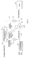
- Figure 2 is a block diagram depicting an embodiment with a reformer and SOFC system employing dynamic pressure controls.
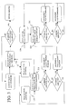
- Figure 3 is a flow diagram depicting a dynamic pressure control algorithm.
- Figure 4 is a block diagram depicting an alternative embodiment with a reformer and SOFC system employing dynamic flow controls.
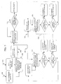
- Figure 5 is a flow diagram depicting a dynamic flow control algorithm.
- SOFC systems including tubular or planar systems. These various systems employ a variety of different cell configurations. Therefore, reference to a particular cell configuration and components for use within a particular cell configuration are intended to also represent similar components in other cell configurations where applicable.
- FIG. 1 depicts a portion of a typical power system 10 employing a SOFC 50 and a reformer 20. Fuel is supplied to the reformer 20, and processed resulting in a reformate 102, which is supplied to the SOFC 50. The reformate 102 is typically metered and controlled via a fixed orifice or valve 40, which restricts the flow of the reformate 102 to the SOFC 50.
- power systems 10 may comprise at least one SOFC 50, an engine, and one or more heat exchangers.
- a power system 10 may include one or more compressors, an exhaust turbine, a catalytic converter, preheating device, an electrical source (e.g., battery, capacitor, motor/generator, or turbine), and conventional connections, wiring, control valves, and a multiplicity of electrical loads, including, but not limited to, lights, resistive heaters, blowers, air conditioning compressors, starter motors, traction motors, computer systems, radio/stereo systems, and a multiplicity of sensors and actuators, and the like, as well as conventional components.
- the SOFC 50 may also be electrically connected with other electrochemical cells or SOFCs.
- a direct supply of simple fuel e.g., hydrogen, carbon monoxide, and/or methane is preferred.
- simple fuel e.g., hydrogen, carbon monoxide, and/or methane
- concentrated supplies of these fuels are generally expensive and difficult to store and supply. Therefore, the fuel utilized may be obtained by processing of a more complex fuel.
- the actual fuel utilized in the system is typically chosen based upon the application, expense, availability, and environmental issues relating to a particular fuel.
- Possible fuels may include conventional fuels such as hydrocarbon fuels, including, but not limited to, conventional liquid fuels, such as gasoline, diesel, ethanol, methanol, kerosene, and others; conventional gaseous fuels, such as natural gas, propane, butane, and others; and alternative or "new" fuels, such as hydrogen, biofuels, dimethyl ether, and others; as well as combinations comprising at least one of the foregoing fuels.
- the preferred fuel is typically based upon the type of engine employed, with lighter fuels, i.e., those which can be more readily vaporized and/or conventional fuels which are readily available to consumers, generally being preferred.
- a reformer 20 generally converts one type of fuel to another, more compatible with the SOFC 50 (e.g., hydrogen).
- a reformer 20 generally converts one type of fuel to another, more compatible with the SOFC 50 (e.g., hydrogen).
- two types of reformer technologies are employed; steam reformers, which employ exothermic reaction, and partial oxidation reformers, which employ an endothermic reaction.
- Steam reformer technology is generally employed for converting methanol to hydrogen.
- Partial oxidation reformers are generally employed for converting gasoline to hydrogen. Typical considerations for the reformers include rapid start, dynamic response time, fuel conversion efficiency, size, and weight.
- the SOFC 50 may be used in conjunction with an engine, for example, to produce tractive power for a vehicle.
- an engine for example, to produce tractive power for a vehicle.
- SOFC effluent, air, and/or fuel are burned to produce energy, while the remainder of unburned fuel and reformed fuel is used as fuel in the SOFC 50.
- the engine can be any conventional combustion engine including, but not limited to, internal combustion engines such as spark ignited and compression ignited engines, including, but not limited to, variable compression engines.
- FIG. 2 depicts a block diagram of an embodiment of the invention as interposed in a power system 10.
- a reformer 20 processes fuel generating a reformate 102.
- a reformate pressure sensor 22 measures the reformate pressure and generates a reformate pressure signal 104, which is transmitted to a controller 30.
- the reformate 102 flows to the SOFC 50 via a controllable valve 60.
- the controllable valve 60 is configured to receive a controllable valve command 108 from the controller 30.
- the controllable valve 60 also includes a position sensor (not shown), which detects the position of the valve and transmits the measured controllable valve position signal 106 representative of that position to the controller 30.
- controller 30 may include, but not be limited to, a processor(s), computer(s), memory, storage, register(s), timing, interrupt(s), communication interfaces, and input/output signal interfaces, as well as combinations comprising at least one of the foregoing.
- controller 30 may include signal input signal filtering to enable accurate sampling and conversion or acquisitions of such signals from communications interfaces. Additional features of controller 30 and certain processes therein are thoroughly discussed at a later point herein.
- Controller 30 receives various input signals including, but not limited to, those identified above, to facilitate such processing and may provide one or more output signals in response.
- the controller 30 receives as input signals: a desired reformate pressure signal 110 representative of the desired reformate pressure, the reformate pressure signal 104, the measured controllable valve position signal 106, and transmits as an output a controllable valve command 108.
- the reformate pressure signal 104 is compared with the desired reformate pressure signal 110 at pressure comparator 210 to formulate a reformate pressure error signal.
- a desired position for the controllable valve 60 is determined in response to the reformate pressure error signal. In an embodiment, if the reformate pressure error is greater than a first pressure error threshold, a desired controllable valve position value 220 is decreased. Likewise, if the reformate pressure error is less than a second pressure error threshold, the desired controllable valve position value 220 is increased. Thereby, a new desired controllable valve position value 220 is generated.
- the pressure error thresholds for both comparisons are set at zero.
- the increase or decrease in the desired controllable valve position value 220 may include, but not be limited to, such functions as a look-up table, scaling, counters, and/or other implementation methodologies for adjusting the set point for the desired controllable valve position value 220.
- the new desired controllable valve position value 220 of the controllable valve 60 may be compared to the measured controllable valve position signal 106.
- the comparison at valve position comparator 230 yields a difference between the desired and measured positions, which is a valve position error.
- the valve position error is then compared to a first position error threshold and a second position error threshold to ascertain if an adjustment in the controllable valve command 108 is warranted.
- valve position error is greater than the first position error threshold
- the controllable valve command 108 is decreased, thereby reducing the controllable valve position and causing the controllable valve 60 to close a predetermined increment.
- the controllable valve command 108 is increased, thereby increasing the controllable valve position and causing the controllable valve to open a predetermined increment. In such a manner, a closed loop control of the pressure to the SOFC 50 is achieved.
- the subtraction at pressure comparator 210 generates a reformate pressure error signal, which if it is less than the second pressure error threshold, increases the desired controllable valve position value 220.
- the increased desired controllable valve position in turn, causes an increase on the controllable valve command 108, thereby resulting in an increase in the controllable valve position, opening the controllable valve 60, causing a decrease in the pressure of the reformate supplied to the SOFC 50.
- controllable valve command 108 may include, but not be limited to, such functions as a look-up table, scaling, counters, and/or other implementation methodologies for adjusting the set point for the desired controllable valve position.
- the measured reformate pressure signal 104 may further be employed in a diagnostic algorithm to facilitate evaluation of proper operation of the reformer 20 and controller 30. For example, the measured reformate pressure signal 104 is compared with a predictive pressure for the operating conditions of the reformer 20. If the comparison should yield an error beyond a predetermined tolerance, corrective measures may be implemented and/or a diagnostic flag may be set to signal the presence of a malfunction.
- FIG. 4 depicts a block diagram of an alternative embodiment on as interposed in a power system 10.
- a mass flow control system similar to the abovementioned pressure control system is disclosed.
- the reformer 20 processes fuel generating a reformate 102.
- the reformate pressure sensor 22 measures the reformate pressure and generates a reformate pressure signal 104, which is transmitted to controller 30.
- the controllable valve 60 meters the reformate 102 as it flows to the SOFC 50.
- the controllable valve 60 is configured to receive the controllable valve command 108 from the controller 30.
- the controllable valve 60 also includes the position sensor (not shown), which detects the position of the valve and transmits a measured controllable valve position signal 106 representative of that position to the controller 30.
- An SOFC pressure sensor 24 measures the pressure of the metered reformate 112 and generates a metered reformate pressure signal 114, which is transmitted to controller 30.
- FIG. 5 a mass flow control algorithm is depicted.
- the mass flow control algorithm again, is similar to the pressure control algorithm of FIG. 3, with the exception of including processing for the metered reformate pressure signal 114.
- the reformate pressure signal 104 is compared with the metered reformate pressure signal 114 at difference 402 to formulate a pressure differential signal.
- the pressure differential signal is converted to an actual mass flow signal 406 utilizing a look up table 404, which is indexed by the pressure differential signal.
- the actual mass flow signal 406 evaluated versus a theoretical mass flow signal at mass flow comparator 410 to determine a mass flow error signal.
- a desired controllable valve position value 220 for the controllable valve 60 is determined, responsive to the mass flow error signal.
- the desired controllable valve position value 220 if the mass flow error is greater than a first mass flow error threshold, the desired controllable valve position value 220 is decreased. Likewise, if the mass flow error is less than a second mass flow error threshold, the desired controllable valve position value 220 is increased. Thereby, a new desired controllable valve position value 220 is generated. Similar to the previously disclosed embodiment, the predetermined thresholds for both comparisons are set at zero. Again, it will be appreciated that a variety of thresholds are possible. Also of note, once again, the method of determining the desired controllable valve position 200 may include the same variations as disclosed earlier.
- the new desired controllable valve position value 220 of the controllable valve 60 may be compared to the measured controllable valve position signal 106.
- the comparison at valve position comparator 230 yields a difference between the desired and measured positions, which is a valve position error.
- the valve position error is then compared to a set of predetermined thresholds to ascertain if an adjustment in the controllable valve command 108 is warranted.
- valve position error if the valve position error is greater than a third position error threshold, the controllable valve command 108 is decreased causing the controllable valve 60 to close a predetermined increment. Likewise, if the valve position error is less than a fourth position error threshold, the controllable valve command 108 is increased causing the controllable valve to open a predetermined increment. Thereby, control of the mass flow to the SOFC 50 is achieved. For example, if the actual mass flow signal 406 of the reformate is too high, the subtraction at mass flow comparator 410 generates a mass flow error signal, which if it is less than the fourth position error threshold, increases the desired controllable valve position value 220.
- the increased desired controllable valve position in turn, causes an decrease on the controllable valve command 108, thereby resulting in a decrease in the position and closing of the controllable valve 60 resulting in a decrease in the mass flow of the reformate supplied to the SOFC 50.
- the method of determining the controllable valve command 108 may include may include the same variety of characteristics as disclosed earlier.
- the actual mass flow signal 406 may further be employed in a diagnostic algorithm to facilitate proper operation of the reformer 20 and controller 30. For example, the actual mass flow signal 406 is compared with a predictive mass flow for the operating conditions of the reformer 20. If the comparison should yield an error in beyond a predetermined tolerance, corrective measures may be implemented and/or a diagnostic flag may be set to signal the malfunction.
- the disclosed method may be embodied in the form of computer-implemented processes and apparatuses for practicing those processes.
- the method can also be embodied in the form of computer program code containing instructions embodied in tangible media, such as floppy diskettes, CD-ROMs, hard drives, or any other computer-readable storage medium, wherein, when the computer program code is loaded into and executed by a computer, the computer becomes an apparatus capable of executing the method.
- the method can also be embodied in the form of computer program code, for example, whether stored in a storage medium, loaded into and/or executed by a computer, or as data signal transmitted whether a modulated carrier wave or not, over some transmission medium, such as over electrical wiring or cabling, through fiber optics, or via electromagnetic radiation, such that, when the computer program code is loaded into and executed by a computer, the computer becomes an apparatus capable of executing the method.
- computer program code segments configure the microprocessor to create specific logic circuits.
- the foregoing disclosure provides in multiple embodiments, methodologies and systems for controlling the reformate applied to an electrochemical cell. Moreover, the same methodologies could be applied to the control of hot gases delivered to an engine, for example an internal combustion engine. Finally, diagnostic methodologies are disclosed that allow for evaluation of operational characteristics and provide a means for detecting malfunctions and leaks in the system.
Landscapes
- Life Sciences & Earth Sciences (AREA)
- Engineering & Computer Science (AREA)
- Manufacturing & Machinery (AREA)
- Sustainable Development (AREA)
- Sustainable Energy (AREA)
- Chemical & Material Sciences (AREA)
- Chemical Kinetics & Catalysis (AREA)
- Electrochemistry (AREA)
- General Chemical & Material Sciences (AREA)
- Fuel Cell (AREA)
Applications Claiming Priority (2)
| Application Number | Priority Date | Filing Date | Title |
|---|---|---|---|
| US09/778,537 US7294421B2 (en) | 2001-02-07 | 2001-02-07 | Solid oxide auxiliary power unit reformate control |
| US778537 | 2001-02-07 |
Publications (2)
| Publication Number | Publication Date |
|---|---|
| EP1231661A2 true EP1231661A2 (de) | 2002-08-14 |
| EP1231661A3 EP1231661A3 (de) | 2005-12-28 |
Family
ID=25113694
Family Applications (1)
| Application Number | Title | Priority Date | Filing Date |
|---|---|---|---|
| EP02075101A Withdrawn EP1231661A3 (de) | 2001-02-07 | 2002-01-14 | Reformatkontrolle in einer Hilfskrafteinheit von Festoxidbrennstoffzellen |
Country Status (2)
| Country | Link |
|---|---|
| US (1) | US7294421B2 (de) |
| EP (1) | EP1231661A3 (de) |
Cited By (1)
| Publication number | Priority date | Publication date | Assignee | Title |
|---|---|---|---|---|
| EP1858100A4 (de) * | 2005-01-11 | 2009-08-12 | Toyota Motor Co Ltd | Brennstoffbatteriesystem |
Families Citing this family (67)
| Publication number | Priority date | Publication date | Assignee | Title |
|---|---|---|---|---|
| US6989208B2 (en) * | 2002-01-28 | 2006-01-24 | Utc Fuel Cells, Llc | Fuel cell power plant used as reformate generator |
| US7067208B2 (en) * | 2002-02-20 | 2006-06-27 | Ion America Corporation | Load matched power generation system including a solid oxide fuel cell and a heat pump and an optional turbine |
| US6924053B2 (en) * | 2003-03-24 | 2005-08-02 | Ion America Corporation | Solid oxide regenerative fuel cell with selective anode tail gas circulation |
| US7575822B2 (en) | 2003-04-09 | 2009-08-18 | Bloom Energy Corporation | Method of optimizing operating efficiency of fuel cells |
| US7364810B2 (en) | 2003-09-03 | 2008-04-29 | Bloom Energy Corporation | Combined energy storage and fuel generation with reversible fuel cells |
| US7482078B2 (en) * | 2003-04-09 | 2009-01-27 | Bloom Energy Corporation | Co-production of hydrogen and electricity in a high temperature electrochemical system |
| US7878280B2 (en) * | 2003-04-09 | 2011-02-01 | Bloom Energy Corporation | Low pressure hydrogen fueled vehicle and method of operating same |
| US7422810B2 (en) * | 2004-01-22 | 2008-09-09 | Bloom Energy Corporation | High temperature fuel cell system and method of operating same |
| US20060147771A1 (en) * | 2005-01-04 | 2006-07-06 | Ion America Corporation | Fuel cell system with independent reformer temperature control |
| US7524572B2 (en) * | 2005-04-07 | 2009-04-28 | Bloom Energy Corporation | Fuel cell system with thermally integrated combustor and corrugated foil reformer |
| US20060251934A1 (en) * | 2005-05-09 | 2006-11-09 | Ion America Corporation | High temperature fuel cell system with integrated heat exchanger network |
| US7858256B2 (en) * | 2005-05-09 | 2010-12-28 | Bloom Energy Corporation | High temperature fuel cell system with integrated heat exchanger network |
| US8691462B2 (en) * | 2005-05-09 | 2014-04-08 | Modine Manufacturing Company | High temperature fuel cell system with integrated heat exchanger network |
| US7700210B2 (en) * | 2005-05-10 | 2010-04-20 | Bloom Energy Corporation | Increasing thermal dissipation of fuel cell stacks under partial electrical load |
| US7520916B2 (en) * | 2005-07-25 | 2009-04-21 | Bloom Energy Corporation | Partial pressure swing adsorption system for providing hydrogen to a vehicle fuel cell |
| US7591880B2 (en) * | 2005-07-25 | 2009-09-22 | Bloom Energy Corporation | Fuel cell anode exhaust fuel recovery by adsorption |
| US20070017368A1 (en) * | 2005-07-25 | 2007-01-25 | Ion America Corporation | Gas separation method and apparatus using partial pressure swing adsorption |
| JP5542333B2 (ja) * | 2005-07-25 | 2014-07-09 | ブルーム エナジー コーポレーション | 電気化学アノードの排気のリサイクルを行う燃料電池システム |
| US9911989B2 (en) * | 2005-07-25 | 2018-03-06 | Bloom Energy Corporation | Fuel cell system with partial recycling of anode exhaust |
| US9190693B2 (en) | 2006-01-23 | 2015-11-17 | Bloom Energy Corporation | Modular fuel cell system |
| US7659022B2 (en) | 2006-08-14 | 2010-02-09 | Modine Manufacturing Company | Integrated solid oxide fuel cell and fuel processor |
| WO2007117406A2 (en) * | 2006-04-03 | 2007-10-18 | Bloom Energy Corporation | Fuel cell system and balance of plant configuration |
| US8822094B2 (en) * | 2006-04-03 | 2014-09-02 | Bloom Energy Corporation | Fuel cell system operated on liquid fuels |
| US8241801B2 (en) | 2006-08-14 | 2012-08-14 | Modine Manufacturing Company | Integrated solid oxide fuel cell and fuel processor |
| EP2064766A4 (de) * | 2006-09-06 | 2010-09-29 | Bloom Energy Corp | Flexible brennstoffzellensystemkonfiguration zur handhabung von mehreren brennstoffen |
| US7968245B2 (en) * | 2006-09-25 | 2011-06-28 | Bloom Energy Corporation | High utilization stack |
| US8748056B2 (en) | 2006-10-18 | 2014-06-10 | Bloom Energy Corporation | Anode with remarkable stability under conditions of extreme fuel starvation |
| US10615444B2 (en) | 2006-10-18 | 2020-04-07 | Bloom Energy Corporation | Anode with high redox stability |
| WO2008051368A2 (en) * | 2006-10-23 | 2008-05-02 | Bloom Energy Corporation | Dual function heat exchanger for start-up humidification and facility heating in sofc system |
| JP5157126B2 (ja) * | 2006-10-31 | 2013-03-06 | トヨタ自動車株式会社 | 燃料電池システム |
| JP5076472B2 (ja) * | 2006-12-05 | 2012-11-21 | トヨタ自動車株式会社 | 燃料電池システム |
| US7393603B1 (en) * | 2006-12-20 | 2008-07-01 | Bloom Energy Corporation | Methods for fuel cell system optimization |
| US7883803B2 (en) * | 2007-03-30 | 2011-02-08 | Bloom Energy Corporation | SOFC system producing reduced atmospheric carbon dioxide using a molten carbonated carbon dioxide pump |
| US7833668B2 (en) * | 2007-03-30 | 2010-11-16 | Bloom Energy Corporation | Fuel cell system with greater than 95% fuel utilization |
| US20080254336A1 (en) * | 2007-04-13 | 2008-10-16 | Bloom Energy Corporation | Composite anode showing low performance loss with time |
| US20080261099A1 (en) * | 2007-04-13 | 2008-10-23 | Bloom Energy Corporation | Heterogeneous ceramic composite SOFC electrolyte |
| WO2008150524A2 (en) | 2007-06-04 | 2008-12-11 | Bloom Energy Corporation | Structure for high temperature fuel cell system start up and shutdown |
| US8920997B2 (en) | 2007-07-26 | 2014-12-30 | Bloom Energy Corporation | Hybrid fuel heat exchanger—pre-reformer in SOFC systems |
| US8852820B2 (en) | 2007-08-15 | 2014-10-07 | Bloom Energy Corporation | Fuel cell stack module shell with integrated heat exchanger |
| US9246184B1 (en) | 2007-11-13 | 2016-01-26 | Bloom Energy Corporation | Electrolyte supported cell designed for longer life and higher power |
| CN105206847B (zh) | 2007-11-13 | 2018-02-09 | 博隆能源股份有限公司 | 针对较长寿命和较高电力设计的电解质支撑型电池 |
| WO2009105191A2 (en) | 2008-02-19 | 2009-08-27 | Bloom Energy Corporation | Fuel cell system containing anode tail gas oxidizer and hybrid heat exchanger/reformer |
| US8968958B2 (en) | 2008-07-08 | 2015-03-03 | Bloom Energy Corporation | Voltage lead jumper connected fuel cell columns |
| US9287571B2 (en) | 2008-07-23 | 2016-03-15 | Bloom Energy Corporation | Operation of fuel cell systems with reduced carbon formation and anode leading edge damage |
| WO2010082913A1 (en) * | 2009-01-15 | 2010-07-22 | Utc Power Corporation | System and method for reducing fuel cell power plant emissions |
| US20100256888A1 (en) * | 2009-04-07 | 2010-10-07 | General Electric Company | Method and system for actively tuning a valve |
| US8617763B2 (en) | 2009-08-12 | 2013-12-31 | Bloom Energy Corporation | Internal reforming anode for solid oxide fuel cells |
| EP2474063B1 (de) * | 2009-09-02 | 2017-04-12 | Bloom Energy Corporation | Mehrstrom-wärmetauscher für ein brennstoffzellensystem |
| AU2011209829C1 (en) | 2010-01-26 | 2016-09-01 | Bloom Energy Corporation | Phase stable doped zirconia electrolyte compositions with low degradation |
| US8440362B2 (en) | 2010-09-24 | 2013-05-14 | Bloom Energy Corporation | Fuel cell mechanical components |
| EP2661782B1 (de) | 2011-01-06 | 2018-10-03 | Bloom Energy Corporation | Sofc-heizbehälter-komponenten |
| CN104798237B (zh) | 2012-11-20 | 2018-12-14 | 博隆能源股份有限公司 | 经掺杂氧化钪稳定的氧化锆电解质组合物 |
| US9755263B2 (en) | 2013-03-15 | 2017-09-05 | Bloom Energy Corporation | Fuel cell mechanical components |
| TWI638483B (zh) | 2013-10-23 | 2018-10-11 | 美商博隆能源股份有限公司 | 用於燃料電池系統之陽極復熱器及其操作方法 |
| CN105705226B (zh) | 2013-11-06 | 2018-03-27 | 瓦特燃料电池公司 | 液体燃料催化部分氧化重整器和催化部分氧化重整方法 |
| JP6549601B2 (ja) | 2013-11-06 | 2019-07-24 | ワット・フューエル・セル・コーポレイションWatt Fuel Cell Corp. | ガス状燃料cpox改質器と燃料セルの統合システム、及び電気を生成する方法 |
| JP6253795B2 (ja) | 2013-11-06 | 2017-12-27 | ワット・フューエル・セル・コーポレイションWatt Fuel Cell Corp. | ガス状燃料cpox改質器及びcpox改質の方法 |
| EP3065854A2 (de) | 2013-11-06 | 2016-09-14 | Watt Fuel Cell Corp. | Reformer mit perowskit als struktureller komponente |
| EP3065861A2 (de) | 2013-11-06 | 2016-09-14 | Watt Fuel Cell Corp. | Chemischer reaktor mit verteiler zur verwaltung eines zustroms eines gasförmigen reaktionsmediums |
| EP3065855B1 (de) | 2013-11-06 | 2022-06-29 | Watt Fuel Cell Corp. | Flüssigbrennstoff-cpox-reformer und brennstoffzellensysteme sowie stromerzeugungsverfahren |
| TWI663771B (zh) | 2014-02-12 | 2019-06-21 | 美商博隆能源股份有限公司 | 多個燃料電池和電力電子供給負載並聯以允許整合電化學阻抗頻譜(eis)之燃料電池系統之結構及方法 |
| US10651496B2 (en) | 2015-03-06 | 2020-05-12 | Bloom Energy Corporation | Modular pad for a fuel cell system |
| US10347930B2 (en) | 2015-03-24 | 2019-07-09 | Bloom Energy Corporation | Perimeter electrolyte reinforcement layer composition for solid oxide fuel cell electrolytes |
| US12266835B2 (en) | 2017-08-28 | 2025-04-01 | Bloom Energy Corporation | SOFC including redox-tolerant anode electrode and method of making the same |
| US10680251B2 (en) | 2017-08-28 | 2020-06-09 | Bloom Energy Corporation | SOFC including redox-tolerant anode electrode and system including the same |
| US11398634B2 (en) | 2018-03-27 | 2022-07-26 | Bloom Energy Corporation | Solid oxide fuel cell system and method of operating the same using peak shaving gas |
| KR20230000972A (ko) | 2021-06-25 | 2023-01-03 | 블룸 에너지 코퍼레이션 | 연료 전지 시스템의 건전성 및 성능을 최대화하기 위한 가변적이고 예측할 수 없는 가스 조성 변화의 처리 |
Citations (2)
| Publication number | Priority date | Publication date | Assignee | Title |
|---|---|---|---|---|
| US4146051A (en) * | 1976-01-10 | 1979-03-27 | Lucas Industries Limited | Fluid flow control system |
| JP2000163134A (ja) * | 1998-09-24 | 2000-06-16 | Aisin Seiki Co Ltd | 流量制御バルブ及び燃料電池システム |
Family Cites Families (14)
| Publication number | Priority date | Publication date | Assignee | Title |
|---|---|---|---|---|
| US5059494A (en) * | 1990-05-10 | 1991-10-22 | International Fuel Cells | Fuel cell power plant |
| US5366821A (en) | 1992-03-13 | 1994-11-22 | Ballard Power Systems Inc. | Constant voltage fuel cell with improved reactant supply and control system |
| JP2888717B2 (ja) | 1992-04-06 | 1999-05-10 | 公生 石丸 | エネルギー供給システム |
| JPH0729589A (ja) * | 1993-07-09 | 1995-01-31 | Ishikawajima Harima Heavy Ind Co Ltd | 燃料電池発電装置におけるプレート型改質器の差圧制御方法 |
| JPH0869808A (ja) * | 1994-08-30 | 1996-03-12 | Toyota Motor Corp | 改質装置と燃料電池システム |
| US5678647A (en) * | 1994-09-07 | 1997-10-21 | Westinghouse Electric Corporation | Fuel cell powered propulsion system |
| US5441821A (en) | 1994-12-23 | 1995-08-15 | Ballard Power Systems Inc. | Electrochemical fuel cell system with a regulated vacuum ejector for recirculation of the fluid fuel stream |
| JP3915139B2 (ja) * | 1996-05-30 | 2007-05-16 | トヨタ自動車株式会社 | 燃料電池発電装置 |
| EP0813264A3 (de) | 1996-06-14 | 2004-02-25 | Matsushita Electric Industrial Co., Ltd. | Brennstoffzellensystem, Brennstoffversorgungssystem für Brennstoffzelle und tragbares elektrisches Gerät |
| JP4000607B2 (ja) | 1996-09-06 | 2007-10-31 | トヨタ自動車株式会社 | 燃料電池の発電装置およびその方法 |
| US5968680A (en) * | 1997-09-10 | 1999-10-19 | Alliedsignal, Inc. | Hybrid electrical power system |
| CA2271498C (en) * | 1998-05-11 | 2007-01-09 | Honda Giken Kogyo Kabushiki Kaisha | Legged mobile robot |
| AT407314B (de) | 1998-11-23 | 2001-02-26 | Vaillant Gmbh | Brennstoffzellenanordnung |
| US6306531B1 (en) * | 1999-07-06 | 2001-10-23 | General Motors Corporation | Combustor air flow control method for fuel cell apparatus |
-
2001
- 2001-02-07 US US09/778,537 patent/US7294421B2/en not_active Expired - Fee Related
-
2002
- 2002-01-14 EP EP02075101A patent/EP1231661A3/de not_active Withdrawn
Patent Citations (2)
| Publication number | Priority date | Publication date | Assignee | Title |
|---|---|---|---|---|
| US4146051A (en) * | 1976-01-10 | 1979-03-27 | Lucas Industries Limited | Fluid flow control system |
| JP2000163134A (ja) * | 1998-09-24 | 2000-06-16 | Aisin Seiki Co Ltd | 流量制御バルブ及び燃料電池システム |
Cited By (2)
| Publication number | Priority date | Publication date | Assignee | Title |
|---|---|---|---|---|
| EP1858100A4 (de) * | 2005-01-11 | 2009-08-12 | Toyota Motor Co Ltd | Brennstoffbatteriesystem |
| US8057948B2 (en) | 2005-01-11 | 2011-11-15 | Toyota Jidosha Kabushiki Kaisha | Fuel cell system that continues operation in the event of a sensor abnormality |
Also Published As
| Publication number | Publication date |
|---|---|
| EP1231661A3 (de) | 2005-12-28 |
| US7294421B2 (en) | 2007-11-13 |
| US20020106544A1 (en) | 2002-08-08 |
Similar Documents
| Publication | Publication Date | Title |
|---|---|---|
| US7294421B2 (en) | Solid oxide auxiliary power unit reformate control | |
| US6230494B1 (en) | Power generation system and method | |
| EP1030395B1 (de) | Energiegewinnungssystem unter Verwendung einer Festoxidbrennstoffzelle auf der Abgasseite einer Brennkraftmaschine | |
| EP1069636B1 (de) | Brennstoffzellenstapel-Überwachungs- und Steuerungssystem | |
| US20070269694A1 (en) | Temperature zones in a solid oxide fuel cell auxiliary power unit | |
| EP2710657B1 (de) | Brennstoffzellensystem | |
| US20030175565A1 (en) | Solid oxide fuel cell system and a method for controlling the same | |
| US6602628B2 (en) | Control system for fuel cell | |
| Dolanc et al. | Control of autothermal reforming reactor of diesel fuel | |
| US20110076579A1 (en) | Fuel cell system and method of controlling a fuel cell system | |
| JP3693291B2 (ja) | 原燃料蒸発装置、原燃料蒸発方法及び原燃料蒸発装置を備えた燃料電池システム | |
| JP2001243968A (ja) | 燃料電池システム内の燃料プロセッサを効率的に加熱するための制御装置及び方法 | |
| US20020107651A1 (en) | Estimate of reformate composition | |
| WO2009119187A1 (ja) | 燃料電池システムとその負荷追従運転方法 | |
| EP2057706B1 (de) | Brennstoffzellensystem | |
| KR102102969B1 (ko) | 엔진 발전량을 시스템 구동에 사용하는 연료전지-엔진 하이브리드 발전 시스템 | |
| Gechev | Progress in fuel cell usage as an auxiliary power unit in heavy-duty vehicles | |
| KR102190941B1 (ko) | 선박 | |
| KR102190938B1 (ko) | 선박 | |
| KR102175736B1 (ko) | 선박 | |
| KR102012365B1 (ko) | 한 쌍의 엔진 흡기온도 제어용 개폐 밸브를 구비한 연료전지-엔진 하이브리드 발전 시스템 | |
| Botti | The revolution through evolution: Delphi solid oxide fuel cell for apu and hydrogen reformation | |
| Desantes et al. | Impact of the Powertrain Sizing on Cradle-to-Grave Emissions and Fuel Cell Degradation in a FCV with a Range-Extender Architecture | |
| KR101993914B1 (ko) | 연료 전지를 포함하는 발전 장치 및 발전 방법 | |
| CN118684192B (zh) | 用于sofc的特种油自热重整反应控制方法及相关设备 |
Legal Events
| Date | Code | Title | Description |
|---|---|---|---|
| PUAI | Public reference made under article 153(3) epc to a published international application that has entered the european phase |
Free format text: ORIGINAL CODE: 0009012 |
|
| AK | Designated contracting states |
Kind code of ref document: A2 Designated state(s): AT BE CH CY DE DK ES FI FR GB GR IE IT LI LU MC NL PT SE TR |
|
| AX | Request for extension of the european patent |
Free format text: AL;LT;LV;MK;RO;SI |
|
| PUAL | Search report despatched |
Free format text: ORIGINAL CODE: 0009013 |
|
| AK | Designated contracting states |
Kind code of ref document: A3 Designated state(s): AT BE CH CY DE DK ES FI FR GB GR IE IT LI LU MC NL PT SE TR |
|
| AX | Request for extension of the european patent |
Extension state: AL LT LV MK RO SI |
|
| RIC1 | Information provided on ipc code assigned before grant |
Ipc: 7H 01M 8/12 B Ipc: 7H 01M 8/06 B Ipc: 7H 01M 8/04 A |
|
| 17P | Request for examination filed |
Effective date: 20060628 |
|
| AKX | Designation fees paid |
Designated state(s): DE FR GB |
|
| 17Q | First examination report despatched |
Effective date: 20071107 |
|
| STAA | Information on the status of an ep patent application or granted ep patent |
Free format text: STATUS: THE APPLICATION IS DEEMED TO BE WITHDRAWN |
|
| 18D | Application deemed to be withdrawn |
Effective date: 20120801 |