EP1231694A1 - Console pour un rail de montage - Google Patents
Console pour un rail de montage Download PDFInfo
- Publication number
- EP1231694A1 EP1231694A1 EP01128001A EP01128001A EP1231694A1 EP 1231694 A1 EP1231694 A1 EP 1231694A1 EP 01128001 A EP01128001 A EP 01128001A EP 01128001 A EP01128001 A EP 01128001A EP 1231694 A1 EP1231694 A1 EP 1231694A1
- Authority
- EP
- European Patent Office
- Prior art keywords
- mounting rail
- telescopic element
- console
- cross
- telescopic
- Prior art date
- Legal status (The legal status is an assumption and is not a legal conclusion. Google has not performed a legal analysis and makes no representation as to the accuracy of the status listed.)
- Withdrawn
Links
Images
Classifications
-
- H—ELECTRICITY
- H02—GENERATION; CONVERSION OR DISTRIBUTION OF ELECTRIC POWER
- H02G—INSTALLATION OF ELECTRIC CABLES OR LINES, OR OF COMBINED OPTICAL AND ELECTRIC CABLES OR LINES
- H02G3/00—Installations of electric cables or lines or protective tubing therefor in or on buildings, equivalent structures or vehicles
- H02G3/26—Installations of cables, lines, or separate protective tubing therefor directly on or in walls, ceilings, or floors
- H02G3/263—Installation, e.g. suspension, of conduit channels or other supports
-
- H—ELECTRICITY
- H02—GENERATION; CONVERSION OR DISTRIBUTION OF ELECTRIC POWER
- H02G—INSTALLATION OF ELECTRIC CABLES OR LINES, OR OF COMBINED OPTICAL AND ELECTRIC CABLES OR LINES
- H02G3/00—Installations of electric cables or lines or protective tubing therefor in or on buildings, equivalent structures or vehicles
- H02G3/30—Installations of cables or lines on walls, floors or ceilings
Definitions
- the invention relates to a console for a mounting rail with the features of The preamble of claim 1.
- the console is for fastening the mounting rail for example, a wall or a post.
- Mounting rails of the type in question are known. They are usually called Rectangular tube profiles with a continuous longitudinal slot on one side and one Row of holes formed on an opposite side.
- the mounting rails will be at a distance parallel to each other, for example on a ceiling or suspended fastened under a ceiling and used for the assembly of, for example, pipes, Cables or also walking and step gratings.
- the assembly can be standing, i.e. on or over the (suspended) mounting rail or hanging under the mounting rail.
- hammer head elements are often inserted in the longitudinal slot of the mounting rail used and by a quarter turn in rear grip with walls of the Mounting rail brought to the side of the longitudinal slot. With one screwed from the outside Nut the hammer head elements are clamped and it can Components such as the pipelines, cables, step and walking grates mentioned on the Hammer head elements are attached.
- a mounting rail in an intermediate space for example between two Walls, a wall and a post or two posts, it must either attached to the ceiling or for attachment to the walls and / or Posts are cut to length exactly to the size of the space.
- the invention is therefore based on the object of a console for fastening a Propose mounting rail in an intermediate space, which is an exact cut to length Makes mounting rail unnecessary.
- the Console according to the invention with the features of claim 1 has a telescopic element on, which can be inserted into one end of the mounting rail in the manner of a telescopic pull-out is.
- the telescopic element of the console according to the invention has one the mounting rail matching or at least substantially matching Cross-sectional shape. Is the mounting rail as a square tube profile with a continuous Longitudinal slit, the telescopic element also has this cross-sectional shape on.
- the telescopic element is around a wall thickness of the mounting rail smaller than this, so outer dimensions of the telescopic element the console internal dimensions correspond to the mounting rail and the telescopic element Can be inserted into one end of the mounting rail in the manner of a telescopic pull-out is.
- the mounting rail is aligned and can be moved in the longitudinal direction held the telescopic element. Due to the displaceability is a length compensation to adapt to the size of the space in which the mounting rail is attached should be possible.
- the mounting rail is cut to length between walls and / or posts that it is shorter than the space.
- the mounting rail is, for example, by means of a Hammer head element clamped to at least one of the two brackets to the Fix the mounting rail so that it cannot move. This can be used for clamping Hammer head element also at the same time for attaching one to the mounting rail serve fastening object.
- the invention has the advantage, first of all, that the mounting rail is cut to length the size of the space in which the mounting rail is to be fastened, is not necessary.
- the mounting rail can have an undersize, for example a few centimeters. This simplifies the effort for cutting to length.
- Another advantage of the invention is that the console the mounting rail without clamping or screwing the mounting rail to the console stably and securely against lifting and in line with the telescopic element of the console. A sticking the mounting rail on the telescopic element of the console to secure against Moving is possible, for example, with a hammer head element for fastening an object to be fastened to the mounting rail anyway is, so that in this case no separate clamping element is necessary.
- Another advantage the invention is that a fastening of an object to be fastened also in the area of the telescopic element and up to a border that delimits the intermediate space Wall or a post delimiting the space is possible.
- the independent claim 2 is directed to the fact that the internal dimensions of the Telescopic element of the console according to the invention outer dimensions of the mounting rail correspond.
- the telescopic element is one Wall thickness of the mounting rail larger than the mounting rail
- the telescopic element the mounting rail on the outer circumference is like a telescopic extension comprehensively attached to the end instead of inserted into the end of the mounting rail.
- a cross-sectional shape of the telescopic element corresponds to the console according to the invention a cross-sectional shape of the mounting rail to be attached to the console.
- the telescopic element of the console according to the invention preferably has a tubular profile with a continuous longitudinal slit.
- the tube profile of the Telescopic element a polygonal tube profile, preferably a square tube profile.
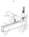
- the console 10 has a base plate 12 on, with two through holes (elongated holes) 14 for screwing the console 10 on, for example, a wall (not shown) or one not shown Serve posts.
- the base plate 12 with the through holes 14 forms a fastening device the console 10.
- From the base plate 12 is a square tube at right angles 16, which has a continuous longitudinal slot 18.
- the square tube 16 is welded to the base plate 12.
- the square tube 16 forms a telescopic element 16 of the console 10 and is referred to below as such.
- a mounting rail 20 is pushed, which according to Art a telescopic guide on the telescopic element 16 of the console 10 is displaceable.
- the mounting rail 20 is like the telescopic element 16 as a square tubular profile a continuous longitudinal slot 22 is formed.
- a cross-sectional shape of the mounting rail 20 corresponds to a cross-sectional shape of the telescopic element 16, however is a cross section of the mounting rail 20 around a wall thickness of the mounting rail 20 larger than the telescopic element 16 of the console 10, so that the mounting rail 20 slidable in the longitudinal direction on the telescopic element 16 is.
- the telescopic element 16 of the console 10 guides the mounting rail 20 in alignment and slidable in the longitudinal direction.
- the mounting rail 20 For fastening the mounting rail 20 in a space between, for example two walls, one wall and one post or two posts (not shown) the mounting rail 20 is a few centimeters shorter than the space cut to length and there are two consoles 10 with their telescopic elements 16 in the Ends of the mounting rail 20 inserted.
- the brackets 10 are on the walls and / or screwed posts, with a length adjustment to the size of the space automatically by moving the telescopic elements 16 of the two brackets 10 takes place in the ends of the mounting rails 20.
- the mounting rail 20 is like this pushed onto the telescopic element 16 that the longitudinal slots 22, 18 of the Mounting rail 20 and the telescopic element 16 are on the same side and are therefore congruent.
- Objects can now be fastened to the mounting rail in a manner known per se 20 are attached.
- the attachment can also be made in the end area of the mounting rail 20 take place in which the telescopic element 16 is inserted. Can too the attachment outside the end of the mounting rail 20 in one out of the mounting rail 20 projecting area of the telescopic element 16, if that Telescopic element 16 protrudes far enough from the mounting rail 20.
- Console 10 it is therefore possible to attach items to everyone anywhere on the mounting rail 20 and also beyond its end on the telescopic element 16 to attach the console 10.
- the attachment is in the longitudinal direction the mounting rail 20 possible at any point in the space, in which the mounting rail 20 is attached to the brackets 10.
- Objects are attached to the mounting rail 20 as in the drawing exemplified in particular with known, so-called hammer head elements.
- These hammer head elements are aligned in the longitudinal direction introduced the longitudinal slot 22, 16 and by a quarter turn transversely to the mounting rail 20 aligned. In the transverse position, the hammer head elements reach behind Wall sections of the mounting rail 20 and the telescopic element 16 laterally Longitudinal slot 22, 18. Since the hammer head elements in the mounting rail or in Telescopic element 16 are located, they are not visible in the drawing. Is visible in the drawing only a threaded shaft 24 of the hammer head elements, either screwed into the hammer head element or in one piece with the hammer head element is.
- a clamping nut 26 is screwed onto the threaded shaft 24 and from the outside clamped against the mounting rail 20 or the telescopic element 16.
- FIG 1 it is easily possible to an object such as a Fasten tube 28 in the end region of the mounting rail 20 into which the telescopic element 16 of the console 10 is inserted.
- the hammer head element used for this clamps at the same time the mounting rail 20 on the telescopic element 16 and fixed thereby the mounting rail 20 on the bracket 10 against displacement.
- the mounting rail is at least on a bracket 10 20 in particular with a hammer head element and a counter-tensioned from the outside Clamping nut or a clamping screw cannot be moved on the telescopic element 16 clamped.
- Figure 1 on the right is the attachment of an object outside the mounting rail 20 in a section of the telescopic element protruding from the mounting rail 20 16 indicated. It can be attached directly to a wall or a post to which the bracket 10 is screwed.
Landscapes
- Engineering & Computer Science (AREA)
- Architecture (AREA)
- Civil Engineering (AREA)
- Structural Engineering (AREA)
- Connection Of Plates (AREA)
- Vehicle Step Arrangements And Article Storage (AREA)
- Clamps And Clips (AREA)
Applications Claiming Priority (2)
| Application Number | Priority Date | Filing Date | Title |
|---|---|---|---|
| DE20102391U DE20102391U1 (de) | 2001-02-10 | 2001-02-10 | Konsole für eine Montageschiene |
| DE20102391U | 2001-02-10 |
Publications (1)
| Publication Number | Publication Date |
|---|---|
| EP1231694A1 true EP1231694A1 (fr) | 2002-08-14 |
Family
ID=7952839
Family Applications (1)
| Application Number | Title | Priority Date | Filing Date |
|---|---|---|---|
| EP01128001A Withdrawn EP1231694A1 (fr) | 2001-02-10 | 2001-11-24 | Console pour un rail de montage |
Country Status (3)
| Country | Link |
|---|---|
| EP (1) | EP1231694A1 (fr) |
| CZ (1) | CZ2002477A3 (fr) |
| DE (1) | DE20102391U1 (fr) |
Families Citing this family (1)
| Publication number | Priority date | Publication date | Assignee | Title |
|---|---|---|---|---|
| CZ303564B6 (cs) * | 2007-07-09 | 2012-12-12 | Katchem Spol. S R. O. | Zpusob výroby polyamidového sorbentu pro stabilizaci nápoju a polyamidový sorbent |
Citations (3)
| Publication number | Priority date | Publication date | Assignee | Title |
|---|---|---|---|---|
| DE3930161C1 (fr) * | 1989-09-09 | 1990-09-13 | Rittal-Werk Rudolf Loh Gmbh & Co Kg, 6348 Herborn, De | |
| WO2001001033A1 (fr) * | 1999-06-30 | 2001-01-04 | Reiker Enterprises, Inc. | Support coulissant pour accessoires, et variantes de ce support |
| EP1114935A2 (fr) * | 2000-01-04 | 2001-07-11 | Fischerwerke Arthur Fischer GmbH & Co. KG | Noeud d'assemblage pour perpendiculairement connecter un rail de mountage à un autre support |
Family Cites Families (4)
| Publication number | Priority date | Publication date | Assignee | Title |
|---|---|---|---|---|
| GB2100115A (en) * | 1981-05-01 | 1982-12-22 | Ainsworth Raymond Peter | Brackets |
| AT398161B (de) * | 1991-08-29 | 1994-10-25 | Valenta Rudolf | Schwenkhalterung |
| US5284313A (en) * | 1992-01-08 | 1994-02-08 | Ablenet, Inc. | Mounting system |
| SE9203106L (sv) * | 1992-10-22 | 1994-02-21 | Lars Hansare | Stativ samt tillbehör för ett stativ |
-
2001
- 2001-02-10 DE DE20102391U patent/DE20102391U1/de not_active Expired - Lifetime
- 2001-11-24 EP EP01128001A patent/EP1231694A1/fr not_active Withdrawn
-
2002
- 2002-02-07 CZ CZ2002477A patent/CZ2002477A3/cs unknown
Patent Citations (3)
| Publication number | Priority date | Publication date | Assignee | Title |
|---|---|---|---|---|
| DE3930161C1 (fr) * | 1989-09-09 | 1990-09-13 | Rittal-Werk Rudolf Loh Gmbh & Co Kg, 6348 Herborn, De | |
| WO2001001033A1 (fr) * | 1999-06-30 | 2001-01-04 | Reiker Enterprises, Inc. | Support coulissant pour accessoires, et variantes de ce support |
| EP1114935A2 (fr) * | 2000-01-04 | 2001-07-11 | Fischerwerke Arthur Fischer GmbH & Co. KG | Noeud d'assemblage pour perpendiculairement connecter un rail de mountage à un autre support |
Also Published As
| Publication number | Publication date |
|---|---|
| DE20102391U1 (de) | 2002-06-20 |
| CZ2002477A3 (cs) | 2002-09-11 |
Similar Documents
| Publication | Publication Date | Title |
|---|---|---|
| EP1380807A1 (fr) | Dispositif de montage d'une lunette de visée pour arme à feu | |
| EP3241974B1 (fr) | Système pour un joint d'étanchéité, en particulier pour un joint de seuil ou pour un joint de sol s'abaissant automatiquement | |
| DE102013008597A1 (de) | Montagesystem zur Befestigung von Führungsschienen | |
| DE29508286U1 (de) | Montageplattenpaar zur Befestigung von Scharnierarmen von Möbelscharnieren o.dgl. | |
| EP2760090A1 (fr) | Système de fixation et kit d'intégration pour le montage d'une passerelle de montage dans une armoire de commande | |
| DE29811962U1 (de) | Leuchtender Konstruktionsboden, insbesondere für in wangenbauweise aufgebaute Möbel | |
| EP2220961B1 (fr) | Dispositif de fixation pour un parasol et une table | |
| DE19923814C1 (de) | Montagezwinge für den Einbau von Fenstern und Türen | |
| EP1541776B1 (fr) | Profilé de fixation | |
| EP1655424B1 (fr) | Régles de dressage et de lissage ajustables | |
| DE20102391U1 (de) | Konsole für eine Montageschiene | |
| EP3168405B1 (fr) | Structure de châssis pour porte coulissante | |
| DE3819512C1 (en) | Shelving system | |
| DE9406364U1 (de) | Tragschiene mit verstellbarer Halterung | |
| EP1323933B1 (fr) | Fixation pour un rail allongé ayant un profil en C avec l'ouverture dirigée vers le bas | |
| EP4417765A1 (fr) | Système de raccordement pour raccorder des parties de garde-corps de garde-corps | |
| DE102014105647B3 (de) | Torantriebsbefestigungsvorrichtung und damit versehene Torantriebsvorrichtung | |
| DE202017107484U1 (de) | Tragvorrichtung mit einem Tragarm zum Tragen eines Gegenstandes | |
| EP0348731B1 (fr) | Mât d'acier tubulaire avec rail de montage rapporté pour bloc de connexion | |
| DE202021105975U1 (de) | Türfutterstrebe | |
| EP2896861B1 (fr) | Console de montage réglable destinée à la fixation d'un canal de guidage de conduite sur un mur | |
| DE102021128461A1 (de) | Türfutterstrebe | |
| DE20111212U1 (de) | Vorrichtung zur Befestigung einer Fülltafel | |
| EP2480736B1 (fr) | Profilé protecteur pour encadrements de fenêtre ou de porte | |
| DE20109680U1 (de) | Vorrichtung zur Befestigung einer Metallsäule |
Legal Events
| Date | Code | Title | Description |
|---|---|---|---|
| PUAI | Public reference made under article 153(3) epc to a published international application that has entered the european phase |
Free format text: ORIGINAL CODE: 0009012 |
|
| AK | Designated contracting states |
Kind code of ref document: A1 Designated state(s): AT BE CH CY DE DK ES FI FR GB GR IE IT LI LU MC NL PT SE TR |
|
| AX | Request for extension of the european patent |
Free format text: AL;LT;LV;MK;RO;SI |
|
| 17P | Request for examination filed |
Effective date: 20021221 |
|
| AKX | Designation fees paid |
Designated state(s): AT BE CH CY DE DK ES FI FR GB GR IE IT LI LU MC NL PT SE TR |
|
| 17Q | First examination report despatched |
Effective date: 20040716 |
|
| STAA | Information on the status of an ep patent application or granted ep patent |
Free format text: STATUS: THE APPLICATION IS DEEMED TO BE WITHDRAWN |
|
| 18D | Application deemed to be withdrawn |
Effective date: 20041127 |