EP1231730A2 - Sous-système laser à emission continue - Google Patents
Sous-système laser à emission continue Download PDFInfo
- Publication number
- EP1231730A2 EP1231730A2 EP01303184A EP01303184A EP1231730A2 EP 1231730 A2 EP1231730 A2 EP 1231730A2 EP 01303184 A EP01303184 A EP 01303184A EP 01303184 A EP01303184 A EP 01303184A EP 1231730 A2 EP1231730 A2 EP 1231730A2
- Authority
- EP
- European Patent Office
- Prior art keywords
- optical
- wavelength
- series
- array
- laser
- Prior art date
- Legal status (The legal status is an assumption and is not a legal conclusion. Google has not performed a legal analysis and makes no representation as to the accuracy of the status listed.)
- Withdrawn
Links
Images


Classifications
-
- H—ELECTRICITY
- H04—ELECTRIC COMMUNICATION TECHNIQUE
- H04B—TRANSMISSION
- H04B10/00—Transmission systems employing electromagnetic waves other than radio-waves, e.g. infrared, visible or ultraviolet light, or employing corpuscular radiation, e.g. quantum communication
- H04B10/50—Transmitters
- H04B10/501—Structural aspects
- H04B10/506—Multiwavelength transmitters
-
- H—ELECTRICITY
- H04—ELECTRIC COMMUNICATION TECHNIQUE
- H04B—TRANSMISSION
- H04B10/00—Transmission systems employing electromagnetic waves other than radio-waves, e.g. infrared, visible or ultraviolet light, or employing corpuscular radiation, e.g. quantum communication
- H04B10/50—Transmitters
- H04B10/501—Structural aspects
- H04B10/503—Laser transmitters
- H04B10/505—Laser transmitters using external modulation
Definitions
- the present invention relates to the construction of dense wavelength division multiplexing (DWDM) systems, and in particular, discloses a system for the efficient construction of interfacing cards for such a system.
- DWDM dense wavelength division multiplexing
- DWDM dense wavelength division multiplexing
- wavelength division multiplexing systems require the ability to combine and separate a large number of single channels which have closely spaced apart wavelengths.
- a substantial number of wavelength dependent facilities must be provided.
- each separate wavelength of operation must be independently managed and controlled with laser emitters or modulators and the like.
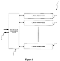
- FIG. 1 there is illustrated schematically an arrangement of the prior art showing a typical DWDM system 1 provided with a series e.g. 2, 3, 4 of interface cards comprising wavelength dependent transmitter, modulator and receiver elements.
- Each element e.g. 2 includes a wavelength dependent laser light source, a modulator for modulating the light source and receiver for detecting the return channel signal.
- the signals are multiplexed and demultiplexed by a dense wavelength division multiplexer 5 for being input and output on input/output optical fibre 6.
- the interface card is wavelength dependent primarily because it comprises a single wavelength optical source such as a distributed feedback (DFB) semiconductor laser diode.
- the output wavelength of a DFB laser is determined at manufacture, and can only be tuned over a very limited range by controlling the temperature of operation of the laser. This range is typically sufficient to enable the output wavelength to be aligned precisely to the intended DWDM channel wavelength, but not to enable the wavelength to be tuned to other DWDM channels. Accordingly, it is generally true that with the arrangement of Figure 1 the output wavelength of each interface card e.g. 2, 3, 4 is determined at the time of manufacture, and cannot be subsequently altered. Hence, it is necessary for the complex provisioning of spares to be undertaken and complex manufacturing resource planning must also be undertaken so as to provide for a wavelength dependent interface card.
- DFB distributed feedback
- tuneable semiconductor sources could be, for example, two- or three-section distributed Bragg reflector (DBR) lasers or multi-section gain-coupled sampled-grating reflector (GCSR) lasers.
- DBR distributed Bragg reflector
- GCSR multi-section gain-coupled sampled-grating reflector
- an optical modulation system for independently modulating multiple wavelengths and transmitting them along a single output waveguide, the system comprising: a series of optical modulator elements each having at least one modulator waveguide input for inputting a single wavelength and modulation means for modulating the input single wavelength to produce a modulated wavelength output; an array of optical laser emitters, each emitting at a separate wavelength, the array having a series of wavelength outputs, one each of which is interconnected to the waveguide modulator input of the series of optical modulator elements; and an optical multiplexer taking a series of a modulated wavelength outputs having differing wavelengths and for multiplexing the multiple wavelengths together for output onto the single output waveguide;
- the array of optical laser emitters preferably can include a continuous wave laser subsystem.
- the optical multiplexer further can comprise a demultiplexer for demultiplexing a signal fed along the single output waveguide into a series of spatially displaced independent wavelength channels for output to the optical modulator elements, the optical modulator elements further comprising a receiver for detecting the signal on a received wavelength channel.
- the system can be located on a series of subracks and the optical modulator elements are preferably located on a separate subrack from the optical laser emitters and are preferably connected thereto by a series of detachable optical waveguides.
- the array of optical laser emitters preferably can include a series of fibre lasers interconnected to at least two pump sources wherein substantially each fibre laser can be independently connected to each pump source.
- the interconnection can be via redundant optical couplers.
- the system further can comprise a series of variable optical attenuators interconnected with the fibre lasers so as to provide variable optical attenuation of the output of the fibre lasers.
- the degree of attenuation can be such that upon failure of one of the pump sources, the degree of attenuation can be adjusted to provide an output in excess of a predetermined intensity level.
- the optical laser emitters comprise a discrete single wavelength semiconductor laser or a semiconductor laser array.
- the modulation means can include an electro absorption modulator or a Mach-Zehnder modulator.
- interconnection between the optical modulator elements and the optical laser emitters can be by means of polarisation maintaining fibres.
- the active interface card is made wavelength independent thereby substantially reducing the problems associated with providing spares and unique wavelength dependant manufacturing.
- a separate source of continuous wavelength laser light is input to the interface card which modulates the data onto its predetermined wavelength.
- the receiver located on the interface card may comprise a conventional semiconductor photodiode or avalanche photodiode. As such, it is wavelength independent within the DWDM signal band due to the inherent broadband nature of such devices.
- the overall arrangement can be as illustrated schematically in Figure 2 with a CW laser array feeding into a series of wavelength independent interface cards e.g. 12, 13, 14.
- the interface cards, 12, 13, 14 each modulate a particular wavelength which is then multiplexed together by multiplexer 15.
- the removal of the laser source from the interface cards enables the interface cards to be wavelength independent. As they have no laser source they will also consume less power and can be potentially made of a smaller fit.
- the rearrangement requires an extra optical interconnect between the CW laser array and the interface cards for feeding the CW laser source for modulation to each card after which the signal can be output via the normal connection.
- the modulator on the interface card may be an electro-absorption (EA) modulator.
- EA modulator has the advantage that it may be made insensitive to the polarisation of the input light. Accordingly, it is not necessary to control the polarisation of the light within the waveguides connecting the CW laser source outputs to the modulator inputs.
- the EA modulator may not be entirely wavelength independent, providing for an operating bandwidth of, e.g. up to 20 nm, which may not be sufficient to cover the full wavelength range in a DWDM communications system. It may therefore be necessary to provide a small number of different interface cards, each comprising an EA modulator optimised for use in a different wavelength range. While this will significantly alleviate the problem of spares provisioning, it will not eliminate it entirely.
- the modulator on the interface card may be a lithium niobate Mach-Zehnder modulator (MZM).
- MZM has the advantage of being insensitive to the wavelength of the input light, within the DWDM communication band. Accordingly, it would not be necessary to provide different interface cards to cover different wavelength bands, thus eliminating completely the problem of spares provisioning.
- the MZM is typically sensitive to the polarisation of the input light. It may therefore be necessary to control the polarisation of the light within the waveguides connecting the CW laser source outputs to the modulator inputs.
- the interconnecting waveguides may be constructed from polarisation maintaining optical fibres.
- the CW laser array can be mounted on a separate subrack and consist of an array of continuous wavelength lasers. These lasers can be integrated to form a single source array or can be an array of discrete lasers.
- the output from the CW laser subrack is an array of fibres each carrying a CW source locked to the appropriate wavelength.
- the CW laser subrack can consist of an array of single-wavelength continuous wave (CW) semiconductor lasers, such as discrete DFB lasers. While such lasers rely on a mature technology, the disadvantage is that the array of CW semiconductor lasers is likely to have a larger footprint than the interface subrack by itself and that the lasers themselves will require many active components for temperature, output power and wavelength control. As such, many of the disadvantages of wavelength dependent transponders regarding manufacturing and sparing will be simply transferred from the wavelength independent interface cards to the CW laser array.
- CW continuous wave
- the CW laser subrack can consist of a smaller number of devices, each comprising an integrated array of say between eight and sixteen DFB lasers in a single package. This will reduce the overall footprint of the CW lasers, as well as the number of active components required, thus alleviating some of the disadvantages associated with the use of discrete DFB lasers.
- An alternative arrangement can be to utilise fibre lasers in the CW array.
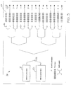
- a more convenient arrangement utilising fibre lasers can be as illustrated 20 in Figure 3 wherein two 980 nm pump lasers 21, 22 are utilised to drive a series of fibre lasers e.g. 23, with the pump lasers being shared amongst the fibre lasers by means of a series of 3-dB couplers e.g. 25.
- Each pump laser has a footprint, and requires active control, equivalent to that of a single CW DFB laser.
- the fibre lasers e.g. 23 do not require active temperature or wavelength stabilisation and are connected to the pump lasers by a series of standard optical connectors e.g. the SC/APC type connectors 26. Further the output of each fibre laser 23 is also connected by a standard optical connector e.g. the SC/APC type connector 27.
- each pump laser e.g. 31, 32 is independently utilised to interconnect with each fibre laser e.g. 33 via a series of 3-dB couplers e.g. 34 and SC/APC connectors e.g. 35.
- Each pump laser 31, 32 is utilised to drive each fibre laser e.g. 33.
- the arrangement of Figure 4 has a reduced possibility of failure as it will be appreciated that the failure of any single component, i.e. a pump laser e.g. 31, a 3-dB coupler e.g. 34 or a connector e.g. 35, will not result in a failure of any laser e.g. 33.
- the arrangement of Figure 4 can be further modified by placing a 980/1550 WDM after each fibre laser so as to filter off any unused pump light and feed this back into an unused 3-dB coupler input.
- an active power control arrangement may be utilised such that shown 40 in Figure 5.
- VOA's variable optical attenuators
- the variable optical attenuators can be utilised to power balance each output from a corresponding fibre laser 42.
- the variable optical attenuators can be set to a level such that, in the event of failure of one of the 980nm pumps, the attenuation of the VOA is reduced so as to keep the output power constant.
- the 980nm pump can then be hot swappable so that the failed unit can be replaced and the VOA's set to normal operating point.
- the arrangements as previously discussed provide the advantage of removing the wavelength dependence from the modulator and receiver interface cards, thus simplifying the manufacture and spares provisioning of the interface cards.
- fibre lasers are utilised for the supply of CW light there is the opportunity for reducing the power consumption of network elements and passive wavelength locking.
- the pump sources can fail and be replaced without interruption to the live traffic.
- the passive fibre lasers themselves may have higher availability and lower probability of failure thereby leading to lower operation and maintenance and ongoing costs. This is likely to be at the expense of higher upfront costs for the use of a CW laser subrack and a larger footprint than an alternative solution using conventional wavelength dependent transponders.
Landscapes
- Physics & Mathematics (AREA)
- Electromagnetism (AREA)
- Engineering & Computer Science (AREA)
- Computer Networks & Wireless Communication (AREA)
- Signal Processing (AREA)
- Optics & Photonics (AREA)
- Optical Communication System (AREA)
Applications Claiming Priority (2)
| Application Number | Priority Date | Filing Date | Title |
|---|---|---|---|
| US782601 | 2001-02-12 | ||
| US09/782,601 US20020109896A1 (en) | 2001-02-12 | 2001-02-12 | Continuous wave laser subsystem |
Publications (1)
| Publication Number | Publication Date |
|---|---|
| EP1231730A2 true EP1231730A2 (fr) | 2002-08-14 |
Family
ID=25126578
Family Applications (1)
| Application Number | Title | Priority Date | Filing Date |
|---|---|---|---|
| EP01303184A Withdrawn EP1231730A2 (fr) | 2001-02-12 | 2001-04-04 | Sous-système laser à emission continue |
Country Status (2)
| Country | Link |
|---|---|
| US (1) | US20020109896A1 (fr) |
| EP (1) | EP1231730A2 (fr) |
Families Citing this family (2)
| Publication number | Priority date | Publication date | Assignee | Title |
|---|---|---|---|---|
| JP4175051B2 (ja) * | 2002-08-02 | 2008-11-05 | 日本電気株式会社 | 光伝送システム及び光伝送システムの光増幅方法 |
| US7245833B1 (en) * | 2002-11-15 | 2007-07-17 | Itt Manufacturing Enterprises, Inc. | Photonic channelized RF receiver employing dense wavelength division multiplexing |
-
2001
- 2001-02-12 US US09/782,601 patent/US20020109896A1/en not_active Abandoned
- 2001-04-04 EP EP01303184A patent/EP1231730A2/fr not_active Withdrawn
Also Published As
| Publication number | Publication date |
|---|---|
| US20020109896A1 (en) | 2002-08-15 |
Similar Documents
| Publication | Publication Date | Title |
|---|---|---|
| EP1434375B1 (fr) | Unité de réseau optique, séparateur optique et système d'accès optique à multiplexage de longueurs d'ondes | |
| US8233510B2 (en) | Dual output laser source | |
| US8965203B1 (en) | Flexible non-modular data center with reconfigurable extended-reach optical network fabric | |
| US9385814B2 (en) | Wavelength tunable array for data communications | |
| EP2997405B1 (fr) | Module émetteur-récepteur optique compact à plusieurs canaux | |
| US20100266283A1 (en) | Wdm pon with distribution via cyclic array waveguide grating | |
| US9225454B1 (en) | Aggregation and de-agreggation of bandwidth within data centers using passive optical elements | |
| US10908369B1 (en) | Flexible onboard optics for networking switches | |
| EP0688114A1 (fr) | Système de télécommunication bidirectionnel à fibre optique utilisant une source à plusieurs longueurs d'ondes à un mode de division au longueur d'onde (WDM) intégrée monolithique et une source optique et incohérente à large bande | |
| EP1341333A2 (fr) | Longueur d'ondes modulées multiples dans un laser compact | |
| WO2014020618A1 (fr) | Laser fabry-perot à cavité externe | |
| US10404035B2 (en) | Reliable laser light source | |
| US6829438B2 (en) | Add/drop multiplexing in WDM optical networks | |
| CN105453464A (zh) | 具有外部调制过滤的激光器阵列的wdm系统 | |
| US20140139900A1 (en) | Wavelength tunable optical transmitter | |
| US9768585B2 (en) | Tunable laser including parallel lasing cavities with a common output | |
| US7019907B2 (en) | Integrated lithium niobate based optical transmitter | |
| US10261276B2 (en) | Datacenter interconnection system | |
| EP1231730A2 (fr) | Sous-système laser à emission continue | |
| AU2002100264A4 (en) | Continuous wave laser subsystem | |
| WO2023164213A1 (fr) | Système de communication optique à alimentation optique à distance simplifiée | |
| EP2671331B1 (fr) | Système, puce laser sur cmos et procédé de réglage d'une longueur d'onde à utiliser par la puce laser sur cmos | |
| JP3808464B2 (ja) | 光ネットワークユニット,波長分岐器および光波長多重アクセスシステム | |
| EP3576320A1 (fr) | Émetteur basé sur un laser à longueurs d'onde multiples et un filtre optique périodique | |
| KR20240052653A (ko) | 착탈식 광원 공급 장치 및 이를 구비한 광트랜시버 |
Legal Events
| Date | Code | Title | Description |
|---|---|---|---|
| PUAI | Public reference made under article 153(3) epc to a published international application that has entered the european phase |
Free format text: ORIGINAL CODE: 0009012 |
|
| AK | Designated contracting states |
Kind code of ref document: A2 Designated state(s): AT BE CH CY DE DK ES FI FR GB GR IE IT LI LU MC NL PT SE TR |
|
| AX | Request for extension of the european patent |
Free format text: AL;LT;LV;MK;RO;SI |
|
| STAA | Information on the status of an ep patent application or granted ep patent |
Free format text: STATUS: THE APPLICATION HAS BEEN WITHDRAWN |
|
| 18W | Application withdrawn |
Effective date: 20031204 |