EP1231987B1 - Feuerbekämpfungseinrichtung - Google Patents
Feuerbekämpfungseinrichtung Download PDFInfo
- Publication number
- EP1231987B1 EP1231987B1 EP00972948A EP00972948A EP1231987B1 EP 1231987 B1 EP1231987 B1 EP 1231987B1 EP 00972948 A EP00972948 A EP 00972948A EP 00972948 A EP00972948 A EP 00972948A EP 1231987 B1 EP1231987 B1 EP 1231987B1
- Authority
- EP
- European Patent Office
- Prior art keywords
- installation
- fire
- spray heads
- unit
- extinguishing medium
- Prior art date
- Legal status (The legal status is an assumption and is not a legal conclusion. Google has not performed a legal analysis and makes no representation as to the accuracy of the status listed.)
- Expired - Lifetime
Links
- 238000009434 installation Methods 0.000 title claims abstract description 57
- 239000007921 spray Substances 0.000 claims abstract description 81
- 230000000694 effects Effects 0.000 claims abstract description 22
- 238000005086 pumping Methods 0.000 claims abstract description 11
- 230000003213 activating effect Effects 0.000 claims description 3
- 230000007423 decrease Effects 0.000 claims description 3
- 230000008878 coupling Effects 0.000 claims description 2
- 238000010168 coupling process Methods 0.000 claims description 2
- 238000005859 coupling reaction Methods 0.000 claims description 2
- 230000005855 radiation Effects 0.000 description 2
- XLYOFNOQVPJJNP-UHFFFAOYSA-N water Substances O XLYOFNOQVPJJNP-UHFFFAOYSA-N 0.000 description 2
- 239000003708 ampul Substances 0.000 description 1
- 238000010276 construction Methods 0.000 description 1
- 239000007788 liquid Substances 0.000 description 1
- 238000000034 method Methods 0.000 description 1
- 230000003287 optical effect Effects 0.000 description 1
- 239000000779 smoke Substances 0.000 description 1
Images



Classifications
-
- A—HUMAN NECESSITIES
- A62—LIFE-SAVING; FIRE-FIGHTING
- A62C—FIRE-FIGHTING
- A62C35/00—Permanently-installed equipment
- A62C35/58—Pipe-line systems
- A62C35/60—Pipe-line systems wet, i.e. containing extinguishing material even when not in use
-
- A—HUMAN NECESSITIES
- A62—LIFE-SAVING; FIRE-FIGHTING
- A62C—FIRE-FIGHTING
- A62C3/00—Fire prevention, containment or extinguishing specially adapted for particular objects or places
- A62C3/07—Fire prevention, containment or extinguishing specially adapted for particular objects or places in vehicles, e.g. in road vehicles
-
- A—HUMAN NECESSITIES
- A62—LIFE-SAVING; FIRE-FIGHTING
- A62C—FIRE-FIGHTING
- A62C37/00—Control of fire-fighting equipment
- A62C37/08—Control of fire-fighting equipment comprising an outlet device containing a sensor, or itself being the sensor, i.e. self-contained sprinklers
Definitions
- the invention relates to an installation for fighting fire in a unit, the installation comprising several spray heads whereof a number that is smaller than the total number of spray heads can be activated according to the location of the fire in the unit, and a drive source for delivering extinguishing medium through a pipe system to the activated spray heads, the drive source comprising a pump unit including a pump in order to provide by an effect of the pump unit a pumping pressure for pumping extinguishing medium into the activated spray head/heads, the pump unit comprising a control unit arranged to increase the extinguishing medium flow of the pump unit when the number of releasing spray heads increases.
- Known fire fighting installations are generally arranged to provide a particular mainly constant flow from every spray head or sprinkler, i.e. a spray head comprising a release means (typically an ampoule that explodes at high temperatures) irrespective of the number of spray heads and sprinklers in the fire fighting installation.
- a constant flow for each spray head thus applies, irrespective of the number of releasing spray heads in the installation, If the installation comprises a larger number of spray heads, these can be divided into fire zones in such a manner that only the zone where fire is detected is released.
- the flow of extinguishing medium for each spray head is constant regardless of the number of released fire zones.
- WO 9425113 discloses a fire fighting system comprising a drive source comprising a pump the rotation speed of which is adjusted in such a way that a predetermined constant value operational pressure is achieved, the flow being allowed to vary. This adjustment is carried out regardless how many sprinklers of the fire fighting system release. The effect of the pump unit thus varies according to the number of sprinklers that release.
- Fire fighting installations are designed in such a way that the drive medium source that drives extinguishing medium to the spray heads has a particular effect that is assumed to provide a certain minimum flow for each spray head. If the installation comprises several spray heads, the effect of the drive medium source has to be high compared with an installation that includes a few spray heads only. This also applies if the installation has several fire zones.
- EP-A2-1 010 441 falling under Article 54(3) EPC discloses such a fire fighting installation.
- control unit is arranged to increase the extinguishing medium flow of the pump unit when the number of the activated spray head/heads increases and the pumping pressure of extinguishing medium decreases in such a way that the effect of the pump unit is substantially kept constant
- effect refers to the working or instantaneous power by keeping the total flow rate to the spray heads times the pumping pressure of the extinguishing medium substantially constant.
- a particularly preferable embodiment of the invention is characterized in that the spray heads are placed in the unit in a number of fire zones, which are activated separately or in groups, comprising a number of spray heads for each fire zone, and in that the installation comprises a number of detectors for activating the fire zones, the detectors being arranged to start delivering extinguishing medium to the respective fire zone when detecting fire, the pump unit being arranged to increase the extinguishing medium flow when the number of activated fire zones and the number of releasing spray heads increase.
- the pump unit preferably comprises 2 to 10 pumps whereof a minimum number is arranged to be coupled in operation depending on the number of activated spray heads, whereby the control unit comprises a gear box for coupling the minimum number of pumps in operation.
- a similar pump unit preferably includes a diesel motor operating with an optimal constant number of revolutions (rpm).
- the installation is particularly suitable for fighting fire in trains and in tunnels and the like, where a fire fighting installation must typically be divided into a number of fire sections.
- the main advantage of the fire fighting installation is to enable a powerful and increased delivery of extinguishing medium from the active spray heads in such a case that only some spray heads in the installation are released.
- the fire can thus be rapidly fought/extinguished using as few as possible of the activated fire zones and using a relatively small amount of extinguishing medium, and the risk of the fire spreading is thus small. In practice it is most likely that only one fire zone or two at the most is activated.
- Figure 1 shows two railway carriages 1, 2 of a train with several railway carriages including a fire fighting installation comprising several sprinklers, i.e. spray heads 3 with release means reacting on heat and mounted along and close to the side walls of the railway carriages.
- a pipe system 4 is arranged to deliver extinguishing medium in the form of water-based liquid from a drive source or a drive unit 5 to the spray heads 3.
- the drive source 5 comprises a pump unit including eight high pressure pumps 50 and an engine 51, for example a diesel engine having a power of 270 kW operating the high pressure pumps, and a control unit 52, 53 that controls the flow and pressure of the pump unit.
- the drive unit can be arranged in a railway carriage 54.
- the spray heads are arranged to be released after the heat-sensitive release means thereof explode or melt at high temperatures.
- a pressure transducer 53 measures the pressure in the pipe system 4 and starts the engine 51 of the pump unit after releasing one of the spray heads 3.
- a different number of pumps 50 is coupled in operation through a gear box 52.
- the engine 51 operates with constant effect (power). If only one pump 50 is coupled in operation, the pressure in the released spray head/heads becomes very high, for example 160 bar.
- the effect of the engine 51 typically the highest possible effect or power of the engine, is fully employed even if only some of the spray heads are released.
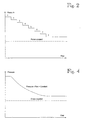
- FIG. 2 illustrates how the pressure changes as a function of the total flow in the spray heads of the installation.
- FIG 3 shows a second preferred embodiment of the invention.
- the same analogue reference numerals are used as in Figure 1 for corresponding components.
- the installation in Figure 2 differs from the one in Figure 1 in that the drive unit 5' comprises a control unit including a pressure transducer 53'.
- the control unit is arranged to adjust the number of revolutions in the diesel engine 51' in order to provide a maximum effect from the pump unit.
- the control unit 53' adjusting the number of revolutions in the diesel engine is not described in this context, as such a control unit can easily be accomplished by those skilled in the art.
- the control unit 53' is preferably arranged to measure the pressure or the pressure changes in the pipe system 4' and thereafter to control the number of revolutions in the diesel engine so that number of revolutions multiplied by the pressure is constant, thus providing an approximately constant effect.
- the maximum number of revolutions and the maximum pressure are both limited.
- Figure 4 shows how the pressure changes as a function of the total flow.
- FIG 5 shows a third embodiment of the invention.
- the fire fighting installation corresponds with the one in Figure 3 except that the spray heads of the railway carriages 1", 2" are divided into fire zones 8"-11", and the spray heads 3" are of such a type that they lack release means that can be activated by heat.
- the spray heads 3" are arranged in fire zones 8"-11", both comprising a respective sectional valve 6", 6a".
- Detectors 7" reacting for example on radiation or smoke, or an optical detector, are arranged to control the respective sectional valves 6" so that these are opened when fire is detected: detector 7a", for example, controls sectional valve 6a" only.
- extinguishing medium flows through a sectional valve 6" and a distribution pipe 40" to the fire zone in which fire is detected.
- Check valves 20" are arranged in the distribution pipe 40". The check valves 20" prevent the spray heads in the fire zone close by and on the same side of the railway carriage to be released if the detector thereof has not provided a signal.
- the installation thus operates in such a manner that a detector 7a", for example, provides a signal, and as a result the sectional valve 6a" is opened, the pump unit 50", 51" is started and extinguishing medium is delivered to the spray heads 3a" which are placed on the right of the check valve 20a".
- the pump unit operates at a constant maximum effect despite the number of activated fire zones, i.e. in spite of e.g. the fire zone 11" also being activated.
- a pump unit can be employed including several pumps and a gear box, as shown in Figure 1.
- control unit in Figure 1 it is an advantage with the control unit in Figure 1 compared with a control unit controlling the number of revolutions in the diesel engine that the total flow within a larger interval can be varied without changing the effect of the pump unit. This is due to the fact that when the number of revolutions is adjusted, the diesel engines are not able to provide a maximum effect when the number of revolutions is small, which is associated with the characteristics of a diesel engine.
- FIG 7 illustrates an installation of the invention mounted in a vehicle tunnel 1''', for example, a train or car tunnel.
- the same analogue reference numerals are used here as in Figures 1 and 2 for corresponding components.
- the tunnel 1''' is divided into six fire zones 8'''-13''' comprising four spray heads 3''' each.
- Each fire zone comprises a sectional valve 6''' respectively. It is obvious that a long tunnel should comprise hundreds, even thousands, of spray heads and many more fire sections and detectors 7''' than what is shown in Figure 7 in order to fight fire along the entire tunnel.
- Some of the sectional valves 6''' can be left out in case the distribution pipes 40''' in the fire zones following one another are connected and check valves are mounted in the same way as the distribution pipes in Figure 5.
- the installation in Figure 7 operates in such a manner that if, for example, the fire detector 7a''' provides a signal, the corresponding sectional valve 6a''' is opened, and the spray heads in the fire zone 9''' start to spray extinguishing medium.
- the pressure becomes very high compared with a situation where several zones, for example the fire zones 8'''-10''', are activated.
- the effect of the pump unit 5''' is set at a constant maximum value, as described above, by means of the control unit 53''' which is of the type that adjusts the number of revolutions in the power source, for example, the diesel engine.
- An engine operating with a constant number of revolution in order to operate a number of pumps through a gear box can alternatively be used.
- the installation in Figures 1, 3, 5 and 7 can preferably be used periodically with reduced effect during a fire fighting process. This holds true particularly in applications where the amount of water is limited to a minimum and a particular protection time is desired so that fire fighters have time to arrive and take control of the fire.
- the capacity of the pump unit of the installation is then adjusted so that the pump unit flow and the installation pressure are reduced to a particular level after radiation heat from the fire is reduced to a certain level. If fire starts again and generates more heat, the pump unit flow and pressure are increased.
- the adjustment of the pumping effect can be implemented by means of connecting a number of pumps or by controlling the number of revolutions in the engine, as described above.
- the number of fire zones and spray heads can vary.
- the installation may comprise combinations of said spray heads with and without release means that can be activated by heat.
- the number of pumps 50 can preferably vary between 2 to 10.
- the drive source for driving the pump/pumps does not have to be a diesel engine, but may also be a frequency or a thyristor-controlled electric engine.
Landscapes
- Health & Medical Sciences (AREA)
- Public Health (AREA)
- Business, Economics & Management (AREA)
- Emergency Management (AREA)
- Fire-Extinguishing By Fire Departments, And Fire-Extinguishing Equipment And Control Thereof (AREA)
- Two-Way Televisions, Distribution Of Moving Picture Or The Like (AREA)
- Buildings Adapted To Withstand Abnormal External Influences (AREA)
- Fire-Detection Mechanisms (AREA)
- Fire-Extinguishing Compositions (AREA)
- Structures Of Non-Positive Displacement Pumps (AREA)
- Chemical Or Physical Treatment Of Fibers (AREA)
- Respiratory Apparatuses And Protective Means (AREA)
Claims (12)
- Brandbekämpfungseinrichtung in einer Einheit, wobei zu der Einrichtung mehrere Sprühköpfe (3,3',3'',3'''), von denen eine Anzahl, die kleiner ist als die Gesamtzahl der Sprühköpfe, gemäß dem Brandort innerhalb der Einheit aktiviert werden kann, und eine Treibquelle (5,5',5'',5''') gehören, die dazu dient, den aktivierten Sprühköpfen durch ein Rohrsystem (4,4',4'',4''') Löschmittel zuzuführen, wobei die Treibquelle eine Pumpeneinheit mit einer Pumpe (50,50',50'',50''') aufweist, um durch eine Wirkung der Pumpeneinheit einen Pumpdruck zum Pumpen von Löschmittel in den/die aktivierten Sprühkopf/Sprühköpfe zu erzeugen, und wobei die Pumpeneinheit eine Kontrolleinheit (52,53,53',53'',53''') aufweist, dadurch gekennzeichnet, dass die Kontrolleinheit (52,53,53',53'',53''') dazu eingerichtet ist, die Löschmittelfördermenge der Pumpeneinheit (50,51,50',51',50'',51'',5''') zu erhöhen, wenn die Anzahl aktivierter Sprühkopf/Sprühköpfe steigt und der Pumpdruck des Löschmittels abnimmt, und zwar so, dass die Leistung der Pumpeneinheit im Wesentlichen konstant gehalten wird, indem das Produkt aus der den Sprühköpfen gelieferten Gesamtförderrate und dem Pumpendruck des Löschmittels im Wesentlichen konstant gehalten wird.
- Einrichtung nach Anspruch 1, dadurch gekennzeichnet, dass die Sprühköpfe (3",3"') in der Einheit in einer Anzahl von Brandzonen (8''-11'',8'''-13'') angeordnet sind, die voneinander unabhängig oder in Gruppen aktiviert werden, wobei jede Brandzone eine Anzahl von Sprühköpfen aufweist, und dass die Einrichtung eine Anzahl von Detektoren (7'',7''') enthält, die zum Aktivieren der Brandzonen (8''-11'',8'''-13''') dienen, wobei die Detektoren dazu eingerichtet sind, die Lieferung von Löschmittel zu den entsprechenden Brandzonen zu starten, wenn ein Brand erfasst wird, wobei die Pumpeneinheit dazu eingerichtet ist, die Löschmittelfördermenge zu steigern, wenn die Anzahl aktivierter Brandzonen und die Anzahl freigebender Sprühköpfe wächst.
- Einrichtung nach Anspruch 1, dadurch gekennzeichnet, dass die Pumpe eine Hochdruckpumpe ist.
- Einrichtung nach Anspruch 3, dadurch gekennzeichnet, dass die Pumpeneinheit 2 - 10 Pumpen (50) aufweist, von denen eine minimale Anzahl dazu eingerichtet ist, in Betrieb abhängig von der Anzahl aktivierter Sprühköpfe (3) angeschlossen zu werden.
- Einrichtung nach Anspruch 4, dadurch gekennzeichnet, dass die Kontrolleinheit einen Getriebekasten (52) aufweist, der dazu dient, in Betrieb eine minimal Anzahl von Pumpen (50) anzuschließen.
- Einrichtung nach Anspruch 1, bei der die Einheit eine längliche Einheit (1,2,1',2',1",2",1''') mit Längsseitenwänden ist, dadurch gekennzeichnet, dass Brandzonen (8"-11",8'''-13''') und Sprühköpfe (3'',3''') entlang der längliche Einheit (1,2,1',2',1'',2",1''') aufeinanderfolgend angeordnet sind.
- Einrichtung gemäß dem Anspruch 6, dadurch gekennzeichnet, dass sich die Brandzonen (8"-11",8'''-13''') entlang der Längsseitenwände der länglichen Einheit (1,2,1',2',1'',2'',1''') so erstrecken, dass beide Seitenwände im Wesentlichen die gleiche Anzahl von Brandzonen aufweisen.
- Einrichtung nach Anspruch 6 oder 7, dadurch gekennzeichnet, dass die Detektoren (7'',7''') dazu eingerichtet sind, Abschnittsventile (6'',6''') zu steuern, die zwischen dem Rohrsystem (4'',4''') und Verteilerrohren (40'',40''') angeordnet sind, die zu Brandzonen (8''-11'',8'''-13''') führen, wobei die Abschnittsventile dazu eingerichtet sind, geöffnet zu werden, wenn die entsprechende Detektoren ein Signal ausgeben, das dazu dient, den entsprechenden Brandzonen Löschmittel zuzuführen.
- Einrichtung nach Anspruch 8, dadurch gekennzeichnet, dass Rückschlagventile (20'') in Verbindung mit den Verteilerrohren (40'') angeordnet sind, wobei die Rückschlagventile dem Löschmittel erlauben, durch ein Abschnittsventil (6") zu den Sprühköpfen in einer Brandzone zu strömen, jedoch verhindern, dass Löschmittel durch das Abschnittsventil zu einer benachbarten Brandzone strömt.
- Einrichtung nach Anspruch 9, dadurch gekennzeichnet, dass einige der aufeinanderfolgenden und benachbarten Brandzonen (8",9" und 10",11") Sprühköpfe aufweisen, die diesen Brandzonen gemeinsam zur Verfügung stehen und dazu eingerichtet sind, Löschmittel zu sprühen, wenn eine dieser Brandzonen aktiviert ist.
- Einrichtung nach Anspruch 1 oder 6, dadurch gekennzeichnet, dass die Einheit ein Waggon (1,2,1',2',1",2") ist.
- Einrichtung nach Anspruch 3, dadurch gekennzeichnet, dass die Einheit ein Tunnel (1''') ist.
Applications Claiming Priority (3)
| Application Number | Priority Date | Filing Date | Title |
|---|---|---|---|
| FI992366A FI108520B (sv) | 1999-11-02 | 1999-11-02 | Installation för att släcka brand |
| FI992366 | 1999-11-02 | ||
| PCT/FI2000/000949 WO2001032268A1 (en) | 1999-11-02 | 2000-11-01 | Installation for fighting fire |
Publications (2)
| Publication Number | Publication Date |
|---|---|
| EP1231987A1 EP1231987A1 (de) | 2002-08-21 |
| EP1231987B1 true EP1231987B1 (de) | 2006-10-11 |
Family
ID=8555546
Family Applications (1)
| Application Number | Title | Priority Date | Filing Date |
|---|---|---|---|
| EP00972948A Expired - Lifetime EP1231987B1 (de) | 1999-11-02 | 2000-11-01 | Feuerbekämpfungseinrichtung |
Country Status (20)
| Country | Link |
|---|---|
| US (1) | US6634432B2 (de) |
| EP (1) | EP1231987B1 (de) |
| JP (1) | JP2003512905A (de) |
| KR (1) | KR100741206B1 (de) |
| CN (1) | CN1165354C (de) |
| AT (1) | ATE342106T1 (de) |
| AU (1) | AU769398B2 (de) |
| CA (1) | CA2388751C (de) |
| DE (1) | DE60031289T2 (de) |
| DK (1) | DK1231987T3 (de) |
| ES (1) | ES2272328T3 (de) |
| FI (1) | FI108520B (de) |
| FR (1) | FR2800290B1 (de) |
| GB (1) | GB2355929B (de) |
| HK (1) | HK1044496B (de) |
| HR (1) | HRP20020385B1 (de) |
| NO (1) | NO20022111L (de) |
| PL (1) | PL194294B1 (de) |
| RU (1) | RU2245183C2 (de) |
| WO (1) | WO2001032268A1 (de) |
Families Citing this family (21)
| Publication number | Priority date | Publication date | Assignee | Title |
|---|---|---|---|---|
| GB2364243B (en) * | 2000-06-05 | 2004-02-25 | Alan Randall | Tunnel fire extinguisher system |
| ES2182720B1 (es) * | 2001-07-31 | 2004-09-16 | Metro De Madrid, S.A. | Sistema y metodo para la proteccion contra incendios en unidades moviles. |
| FI114083B (fi) * | 2002-11-18 | 2004-08-13 | Marioff Corp Oy | Menetelmä suihkutuslaitteiston yhteydessä ja suihkutuslaitteisto |
| KR100637846B1 (ko) * | 2004-08-24 | 2006-10-23 | 샬롬엔지니어링 주식회사 | 열차 자동 화재진압 장치 |
| DE202005013281U1 (de) * | 2005-08-22 | 2006-01-12 | Fogtec Brandschutz Gmbh & Co. Kg | Trockenvorgespanntes Löschsystem für Schienenfahrzeuge |
| US20090056960A1 (en) * | 2007-02-20 | 2009-03-05 | Jack Canady | Warehouse Zoned Sprinkler System |
| FR2946889A3 (fr) | 2009-06-17 | 2010-12-24 | France Manche | Installation de lutte contre un incendie de train dans un tunnel ferroviaire de grande longueur et procede de mise en oeuvre. |
| CN101579560B (zh) * | 2009-06-29 | 2012-10-17 | 四川威特龙消防设备有限公司 | 公共交通车辆消防安全防护系统及方法 |
| IT1396431B1 (it) * | 2009-10-26 | 2012-11-23 | Muller | Carrozza ferroviaria con unita' a getto ad alta pressione per l'estinzione di un incendio e procedimento per l'estinzione di un incendio in una carrozza ferroviaria |
| DE102009053551A1 (de) * | 2009-11-18 | 2011-05-19 | Fogtec Brandschutz Gmbh & Co. Kg | Brandbekämpfungssystem für ein Schienenfahrzeug |
| RU2426571C1 (ru) * | 2010-07-28 | 2011-08-20 | Российская Федерация, от имени которой выступает Министерство промышленности и торговли Российской Федерации (Минпромторг России) | Установка пожаротушения |
| FI125784B (fi) * | 2010-11-08 | 2016-02-15 | Marioff Corp Oy | Palontorjuntajärjestelmän pumppuyksikön sähkömoottoreiden ohjaus |
| GB2493900A (en) * | 2010-12-15 | 2013-02-27 | Kevin Alan Lesley Musk | A multiple water pump system |
| WO2017205725A1 (en) * | 2016-05-27 | 2017-11-30 | Twin City Fan Companies, Ltd. | Tunnel fan and method |
| CN105963889B (zh) * | 2016-06-30 | 2022-02-11 | 程欣 | 一种非固定式消防灭火管网 |
| JP6855283B2 (ja) * | 2017-03-03 | 2021-04-07 | 能美防災株式会社 | スプリンクラ消火設備 |
| ES2736900A1 (es) * | 2018-06-29 | 2020-01-08 | Bayon Javier Seijas | Sistema liquidador de incendios |
| NL2021363B1 (nl) | 2018-07-20 | 2020-01-29 | Hytrans Beheer B V | Blussysteem en werkwijze voor het blussen van branden |
| EP4237101A4 (de) * | 2020-10-29 | 2024-09-18 | Tyco Fire Products LP | Gesteuertes system und verfahren für brandschutz eines automatisierten lager- und wiederauffindungssystems |
| EP4104905A1 (de) * | 2021-06-18 | 2022-12-21 | Carrier Corporation | Brandbekämpfungssysteme und -verfahren |
| KR102688431B1 (ko) * | 2022-05-23 | 2024-08-05 | 주식회사 지에스하이텍 | 대심도 지하차도용 미분무 소화시스템 |
Family Cites Families (17)
| Publication number | Priority date | Publication date | Assignee | Title |
|---|---|---|---|---|
| US3703930A (en) * | 1971-05-27 | 1972-11-28 | Fmc Corp | Automatic sprinkling system |
| US4351394A (en) | 1979-12-28 | 1982-09-28 | Enk William A | Method and system for aircraft fire protection |
| JPS5846351U (ja) * | 1981-09-25 | 1983-03-29 | ホーチキ株式会社 | 消火設備 |
| EP0389469B1 (de) * | 1987-11-17 | 1993-01-07 | Darchem Limited | Flugzeugfeuerschutzeinrichtung |
| GB2215204B (en) * | 1988-02-24 | 1993-12-08 | James Steel | Fire protection system for passenger carriers |
| SU1563715A1 (ru) * | 1988-09-05 | 1990-05-15 | Высшая инженерная пожарно-техническая школа | Узел управлени спринклерной установки пожаротушени |
| US5072792A (en) * | 1989-04-13 | 1991-12-17 | Star Sprinkler Corporation | Concealed sprinkler head assembly |
| JP3109847B2 (ja) * | 1991-02-20 | 2000-11-20 | ホーチキ株式会社 | 消火設備の給水システム |
| CA2111232C (en) * | 1991-06-19 | 2005-08-16 | Goran Sundholm | Method and equipment for fire fighting |
| FI915669A0 (fi) | 1991-11-26 | 1991-11-29 | Goeran Sundholm | Eldslaeckningsanordning. |
| SE501398C2 (sv) * | 1993-04-30 | 1995-02-06 | Htc Aamaal Ab | Förfarande att driva en sprinkleranläggning och anordning för genomförande av förfarandet |
| JPH10118218A (ja) * | 1996-10-16 | 1998-05-12 | Kurita Water Ind Ltd | 消火設備における腐食防止装置 |
| JP3816613B2 (ja) * | 1997-01-14 | 2006-08-30 | 能美防災株式会社 | スプリンクラ消火設備 |
| JPH10248951A (ja) * | 1997-03-12 | 1998-09-22 | Hochiki Corp | トンネル防災システム |
| FI104152B (fi) * | 1997-06-13 | 1999-11-30 | Marioff Corp Oy | Suutin ja palonsammutuslaitteisto |
| FR2769508B1 (fr) * | 1997-10-15 | 1999-12-17 | Jean Aime Andre Poncet | Dispositif d'extinction automatique d'incendie integre a un convoi ferroviaire |
| GB2344762A (en) * | 1998-12-14 | 2000-06-21 | Project Fire Engineers Limited | Fire sprinkler system |
-
1999
- 1999-11-02 FI FI992366A patent/FI108520B/sv not_active IP Right Cessation
- 1999-12-29 FR FR9916629A patent/FR2800290B1/fr not_active Expired - Fee Related
-
2000
- 2000-01-28 GB GB0002072A patent/GB2355929B/en not_active Expired - Fee Related
- 2000-11-01 RU RU2002114334/12A patent/RU2245183C2/ru not_active IP Right Cessation
- 2000-11-01 CN CNB008151415A patent/CN1165354C/zh not_active Expired - Fee Related
- 2000-11-01 HK HK02106194.9A patent/HK1044496B/en not_active IP Right Cessation
- 2000-11-01 WO PCT/FI2000/000949 patent/WO2001032268A1/en not_active Ceased
- 2000-11-01 ES ES00972948T patent/ES2272328T3/es not_active Expired - Lifetime
- 2000-11-01 CA CA002388751A patent/CA2388751C/en not_active Expired - Fee Related
- 2000-11-01 AU AU11506/01A patent/AU769398B2/en not_active Ceased
- 2000-11-01 KR KR1020027005610A patent/KR100741206B1/ko not_active Expired - Fee Related
- 2000-11-01 HR HR20020385A patent/HRP20020385B1/xx not_active IP Right Cessation
- 2000-11-01 AT AT00972948T patent/ATE342106T1/de not_active IP Right Cessation
- 2000-11-01 JP JP2001534471A patent/JP2003512905A/ja active Pending
- 2000-11-01 EP EP00972948A patent/EP1231987B1/de not_active Expired - Lifetime
- 2000-11-01 DE DE60031289T patent/DE60031289T2/de not_active Expired - Lifetime
- 2000-11-01 DK DK00972948T patent/DK1231987T3/da active
- 2000-11-01 PL PL00354537A patent/PL194294B1/pl not_active IP Right Cessation
-
2002
- 2002-03-22 US US10/103,981 patent/US6634432B2/en not_active Expired - Fee Related
- 2002-05-02 NO NO20022111A patent/NO20022111L/no not_active Application Discontinuation
Also Published As
Similar Documents
| Publication | Publication Date | Title |
|---|---|---|
| EP1231987B1 (de) | Feuerbekämpfungseinrichtung | |
| EP1517728B1 (de) | Feuerlöschverfahren und -system | |
| AU2002255020B2 (en) | Fire-fighting installation and drive source of fire-fighting installation | |
| JP3335469B2 (ja) | 消火用スプリンクラー設備の操作法及び該操作法を実施する装置 | |
| US6279663B1 (en) | Nozzle and fire fighting installation | |
| US20110209884A1 (en) | Fire-extinguishing method and apparatus | |
| JPH10192440A (ja) | スプリンクラ消火設備 | |
| RU2076760C1 (ru) | Способ и устройство для пожаротушения | |
| RU2288013C2 (ru) | Способ ликвидации горения в галерейных помещениях | |
| HK1071088B (en) | Method and system for extinguishing a fire | |
| JP2003062106A (ja) | 消火装置 |
Legal Events
| Date | Code | Title | Description |
|---|---|---|---|
| PUAI | Public reference made under article 153(3) epc to a published international application that has entered the european phase |
Free format text: ORIGINAL CODE: 0009012 |
|
| 17P | Request for examination filed |
Effective date: 20020517 |
|
| AK | Designated contracting states |
Kind code of ref document: A1 Designated state(s): AT BE CH CY DE DK ES FI FR GB GR IE IT LI LU MC NL PT SE TR |
|
| AX | Request for extension of the european patent |
Free format text: AL PAYMENT 20020517;LT PAYMENT 20020517;LV PAYMENT 20020517;MK PAYMENT 20020517;RO PAYMENT 20020517;SI PAYMENT 20020517 |
|
| REG | Reference to a national code |
Ref country code: SE Ref legal event code: TRGR |
|
| 17Q | First examination report despatched |
Effective date: 20050404 |
|
| GRAP | Despatch of communication of intention to grant a patent |
Free format text: ORIGINAL CODE: EPIDOSNIGR1 |
|
| GRAS | Grant fee paid |
Free format text: ORIGINAL CODE: EPIDOSNIGR3 |
|
| GRAA | (expected) grant |
Free format text: ORIGINAL CODE: 0009210 |
|
| RAP1 | Party data changed (applicant data changed or rights of an application transferred) |
Owner name: MARIOFF CORPORATION OY |
|
| AK | Designated contracting states |
Kind code of ref document: B1 Designated state(s): AT BE CH CY DE DK ES FI FR GB GR IE IT LI LU MC NL PT SE TR |
|
| AX | Request for extension of the european patent |
Extension state: AL LT LV MK RO SI |
|
| PG25 | Lapsed in a contracting state [announced via postgrant information from national office to epo] |
Ref country code: IT Free format text: LAPSE BECAUSE OF FAILURE TO SUBMIT A TRANSLATION OF THE DESCRIPTION OR TO PAY THE FEE WITHIN THE PRESCRIBED TIME-LIMIT;WARNING: LAPSES OF ITALIAN PATENTS WITH EFFECTIVE DATE BEFORE 2007 MAY HAVE OCCURRED AT ANY TIME BEFORE 2007. THE CORRECT EFFECTIVE DATE MAY BE DIFFERENT FROM THE ONE RECORDED. Effective date: 20061011 Ref country code: BE Free format text: LAPSE BECAUSE OF FAILURE TO SUBMIT A TRANSLATION OF THE DESCRIPTION OR TO PAY THE FEE WITHIN THE PRESCRIBED TIME-LIMIT Effective date: 20061011 Ref country code: FI Free format text: LAPSE BECAUSE OF FAILURE TO SUBMIT A TRANSLATION OF THE DESCRIPTION OR TO PAY THE FEE WITHIN THE PRESCRIBED TIME-LIMIT Effective date: 20061011 Ref country code: NL Free format text: LAPSE BECAUSE OF FAILURE TO SUBMIT A TRANSLATION OF THE DESCRIPTION OR TO PAY THE FEE WITHIN THE PRESCRIBED TIME-LIMIT Effective date: 20061011 |
|
| REG | Reference to a national code |
Ref country code: GB Ref legal event code: FG4D |
|
| REG | Reference to a national code |
Ref country code: CH Ref legal event code: EP |
|
| PG25 | Lapsed in a contracting state [announced via postgrant information from national office to epo] |
Ref country code: IE Free format text: LAPSE BECAUSE OF NON-PAYMENT OF DUE FEES Effective date: 20061101 |
|
| REG | Reference to a national code |
Ref country code: IE Ref legal event code: FG4D |
|
| REF | Corresponds to: |
Ref document number: 60031289 Country of ref document: DE Date of ref document: 20061123 Kind code of ref document: P |
|
| PG25 | Lapsed in a contracting state [announced via postgrant information from national office to epo] |
Ref country code: MC Free format text: LAPSE BECAUSE OF NON-PAYMENT OF DUE FEES Effective date: 20061130 |
|
| REG | Reference to a national code |
Ref country code: DK Ref legal event code: T3 |
|
| PG25 | Lapsed in a contracting state [announced via postgrant information from national office to epo] |
Ref country code: PT Free format text: LAPSE BECAUSE OF FAILURE TO SUBMIT A TRANSLATION OF THE DESCRIPTION OR TO PAY THE FEE WITHIN THE PRESCRIBED TIME-LIMIT Effective date: 20070319 |
|
| LTIE | Lt: invalidation of european patent or patent extension |
Effective date: 20061011 |
|
| NLV1 | Nl: lapsed or annulled due to failure to fulfill the requirements of art. 29p and 29m of the patents act | ||
| REG | Reference to a national code |
Ref country code: HK Ref legal event code: GR Ref document number: 1044496 Country of ref document: HK Ref country code: CH Ref legal event code: NV Representative=s name: FREI PATENTANWALTSBUERO AG |
|
| REG | Reference to a national code |
Ref country code: ES Ref legal event code: FG2A Ref document number: 2272328 Country of ref document: ES Kind code of ref document: T3 |
|
| ET | Fr: translation filed | ||
| PLBE | No opposition filed within time limit |
Free format text: ORIGINAL CODE: 0009261 |
|
| STAA | Information on the status of an ep patent application or granted ep patent |
Free format text: STATUS: NO OPPOSITION FILED WITHIN TIME LIMIT |
|
| 26N | No opposition filed |
Effective date: 20070712 |
|
| PG25 | Lapsed in a contracting state [announced via postgrant information from national office to epo] |
Ref country code: GR Free format text: LAPSE BECAUSE OF FAILURE TO SUBMIT A TRANSLATION OF THE DESCRIPTION OR TO PAY THE FEE WITHIN THE PRESCRIBED TIME-LIMIT Effective date: 20070112 |
|
| PG25 | Lapsed in a contracting state [announced via postgrant information from national office to epo] |
Ref country code: TR Free format text: LAPSE BECAUSE OF FAILURE TO SUBMIT A TRANSLATION OF THE DESCRIPTION OR TO PAY THE FEE WITHIN THE PRESCRIBED TIME-LIMIT Effective date: 20061011 Ref country code: LU Free format text: LAPSE BECAUSE OF NON-PAYMENT OF DUE FEES Effective date: 20061101 |
|
| PG25 | Lapsed in a contracting state [announced via postgrant information from national office to epo] |
Ref country code: CY Free format text: LAPSE BECAUSE OF FAILURE TO SUBMIT A TRANSLATION OF THE DESCRIPTION OR TO PAY THE FEE WITHIN THE PRESCRIBED TIME-LIMIT Effective date: 20061011 |
|
| PGFP | Annual fee paid to national office [announced via postgrant information from national office to epo] |
Ref country code: SE Payment date: 20091126 Year of fee payment: 10 Ref country code: ES Payment date: 20091120 Year of fee payment: 10 Ref country code: DK Payment date: 20091125 Year of fee payment: 10 Ref country code: AT Payment date: 20091130 Year of fee payment: 10 Ref country code: CH Payment date: 20091116 Year of fee payment: 10 Ref country code: DE Payment date: 20091125 Year of fee payment: 10 |
|
| PGFP | Annual fee paid to national office [announced via postgrant information from national office to epo] |
Ref country code: GB Payment date: 20091125 Year of fee payment: 10 Ref country code: IT Payment date: 20091124 Year of fee payment: 10 Ref country code: FR Payment date: 20091214 Year of fee payment: 10 |
|
| REG | Reference to a national code |
Ref country code: SE Ref legal event code: EUG |
|
| REG | Reference to a national code |
Ref country code: CH Ref legal event code: PL |
|
| REG | Reference to a national code |
Ref country code: DK Ref legal event code: EBP |
|
| GBPC | Gb: european patent ceased through non-payment of renewal fee |
Effective date: 20101101 |
|
| PG25 | Lapsed in a contracting state [announced via postgrant information from national office to epo] |
Ref country code: LI Free format text: LAPSE BECAUSE OF NON-PAYMENT OF DUE FEES Effective date: 20101130 Ref country code: CH Free format text: LAPSE BECAUSE OF NON-PAYMENT OF DUE FEES Effective date: 20101130 |
|
| REG | Reference to a national code |
Ref country code: FR Ref legal event code: ST Effective date: 20110801 |
|
| PG25 | Lapsed in a contracting state [announced via postgrant information from national office to epo] |
Ref country code: AT Free format text: LAPSE BECAUSE OF NON-PAYMENT OF DUE FEES Effective date: 20101101 |
|
| REG | Reference to a national code |
Ref country code: DE Ref legal event code: R119 Ref document number: 60031289 Country of ref document: DE Effective date: 20110601 Ref country code: DE Ref legal event code: R119 Ref document number: 60031289 Country of ref document: DE Effective date: 20110531 |
|
| PG25 | Lapsed in a contracting state [announced via postgrant information from national office to epo] |
Ref country code: SE Free format text: LAPSE BECAUSE OF NON-PAYMENT OF DUE FEES Effective date: 20101102 |
|
| PG25 | Lapsed in a contracting state [announced via postgrant information from national office to epo] |
Ref country code: DK Free format text: LAPSE BECAUSE OF NON-PAYMENT OF DUE FEES Effective date: 20101130 Ref country code: FR Free format text: LAPSE BECAUSE OF NON-PAYMENT OF DUE FEES Effective date: 20101130 |
|
| PG25 | Lapsed in a contracting state [announced via postgrant information from national office to epo] |
Ref country code: GB Free format text: LAPSE BECAUSE OF NON-PAYMENT OF DUE FEES Effective date: 20101101 |
|
| PG25 | Lapsed in a contracting state [announced via postgrant information from national office to epo] |
Ref country code: IT Free format text: LAPSE BECAUSE OF NON-PAYMENT OF DUE FEES Effective date: 20101101 |
|
| REG | Reference to a national code |
Ref country code: ES Ref legal event code: FD2A Effective date: 20120110 |
|
| PG25 | Lapsed in a contracting state [announced via postgrant information from national office to epo] |
Ref country code: ES Free format text: LAPSE BECAUSE OF NON-PAYMENT OF DUE FEES Effective date: 20101102 |
|
| PG25 | Lapsed in a contracting state [announced via postgrant information from national office to epo] |
Ref country code: DE Free format text: LAPSE BECAUSE OF NON-PAYMENT OF DUE FEES Effective date: 20110531 |