EP1232010B1 - Module de Pipettage comprenant un système de couplage d'un actionneur - Google Patents
Module de Pipettage comprenant un système de couplage d'un actionneur Download PDFInfo
- Publication number
- EP1232010B1 EP1232010B1 EP00988754A EP00988754A EP1232010B1 EP 1232010 B1 EP1232010 B1 EP 1232010B1 EP 00988754 A EP00988754 A EP 00988754A EP 00988754 A EP00988754 A EP 00988754A EP 1232010 B1 EP1232010 B1 EP 1232010B1
- Authority
- EP
- European Patent Office
- Prior art keywords
- pipetting
- membrane
- micromachined
- macroactuator
- bore
- Prior art date
- Legal status (The legal status is an assumption and is not a legal conclusion. Google has not performed a legal analysis and makes no representation as to the accuracy of the status listed.)
- Expired - Lifetime
Links
Images




Classifications
-
- B—PERFORMING OPERATIONS; TRANSPORTING
- B01—PHYSICAL OR CHEMICAL PROCESSES OR APPARATUS IN GENERAL
- B01L—CHEMICAL OR PHYSICAL LABORATORY APPARATUS FOR GENERAL USE
- B01L3/00—Containers or dishes for laboratory use, e.g. laboratory glassware; Droppers
- B01L3/02—Burettes; Pipettes
- B01L3/0241—Drop counters; Drop formers
- B01L3/0268—Drop counters; Drop formers using pulse dispensing or spraying, eg. inkjet type, piezo actuated ejection of droplets from capillaries
-
- B—PERFORMING OPERATIONS; TRANSPORTING
- B01—PHYSICAL OR CHEMICAL PROCESSES OR APPARATUS IN GENERAL
- B01L—CHEMICAL OR PHYSICAL LABORATORY APPARATUS FOR GENERAL USE
- B01L9/00—Supporting devices; Holding devices
- B01L9/54—Supports specially adapted for pipettes and burettes
-
- G—PHYSICS
- G01—MEASURING; TESTING
- G01N—INVESTIGATING OR ANALYSING MATERIALS BY DETERMINING THEIR CHEMICAL OR PHYSICAL PROPERTIES
- G01N35/00—Automatic analysis not limited to methods or materials provided for in any single one of groups G01N1/00 - G01N33/00; Handling materials therefor
- G01N35/10—Devices for transferring samples or any liquids to, in, or from, the analysis apparatus, e.g. suction devices, injection devices
-
- B—PERFORMING OPERATIONS; TRANSPORTING
- B01—PHYSICAL OR CHEMICAL PROCESSES OR APPARATUS IN GENERAL
- B01L—CHEMICAL OR PHYSICAL LABORATORY APPARATUS FOR GENERAL USE
- B01L2200/00—Solutions for specific problems relating to chemical or physical laboratory apparatus
- B01L2200/14—Process control and prevention of errors
- B01L2200/143—Quality control, feedback systems
- B01L2200/146—Employing pressure sensors
-
- B—PERFORMING OPERATIONS; TRANSPORTING
- B01—PHYSICAL OR CHEMICAL PROCESSES OR APPARATUS IN GENERAL
- B01L—CHEMICAL OR PHYSICAL LABORATORY APPARATUS FOR GENERAL USE
- B01L2300/00—Additional constructional details
- B01L2300/08—Geometry, shape and general structure
- B01L2300/0809—Geometry, shape and general structure rectangular shaped
-
- B—PERFORMING OPERATIONS; TRANSPORTING
- B01—PHYSICAL OR CHEMICAL PROCESSES OR APPARATUS IN GENERAL
- B01L—CHEMICAL OR PHYSICAL LABORATORY APPARATUS FOR GENERAL USE
- B01L2400/00—Moving or stopping fluids
- B01L2400/04—Moving fluids with specific forces or mechanical means
- B01L2400/0403—Moving fluids with specific forces or mechanical means specific forces
- B01L2400/0433—Moving fluids with specific forces or mechanical means specific forces vibrational forces
- B01L2400/0439—Moving fluids with specific forces or mechanical means specific forces vibrational forces ultrasonic vibrations, vibrating piezo elements
-
- B—PERFORMING OPERATIONS; TRANSPORTING
- B01—PHYSICAL OR CHEMICAL PROCESSES OR APPARATUS IN GENERAL
- B01L—CHEMICAL OR PHYSICAL LABORATORY APPARATUS FOR GENERAL USE
- B01L2400/00—Moving or stopping fluids
- B01L2400/04—Moving fluids with specific forces or mechanical means
- B01L2400/0475—Moving fluids with specific forces or mechanical means specific mechanical means and fluid pressure
- B01L2400/0481—Moving fluids with specific forces or mechanical means specific mechanical means and fluid pressure squeezing of channels or chambers
-
- G—PHYSICS
- G01—MEASURING; TESTING
- G01N—INVESTIGATING OR ANALYSING MATERIALS BY DETERMINING THEIR CHEMICAL OR PHYSICAL PROPERTIES
- G01N35/00—Automatic analysis not limited to methods or materials provided for in any single one of groups G01N1/00 - G01N33/00; Handling materials therefor
- G01N2035/00178—Special arrangements of analysers
- G01N2035/00237—Handling microquantities of analyte, e.g. microvalves, capillary networks
-
- Y—GENERAL TAGGING OF NEW TECHNOLOGICAL DEVELOPMENTS; GENERAL TAGGING OF CROSS-SECTIONAL TECHNOLOGIES SPANNING OVER SEVERAL SECTIONS OF THE IPC; TECHNICAL SUBJECTS COVERED BY FORMER USPC CROSS-REFERENCE ART COLLECTIONS [XRACs] AND DIGESTS
- Y10—TECHNICAL SUBJECTS COVERED BY FORMER USPC
- Y10T—TECHNICAL SUBJECTS COVERED BY FORMER US CLASSIFICATION
- Y10T436/00—Chemistry: analytical and immunological testing
- Y10T436/25—Chemistry: analytical and immunological testing including sample preparation
- Y10T436/2575—Volumetric liquid transfer
Definitions
- the invention concerns a pipetting module comprising a micromachined pipetting device and comprising a system for coupling a macroactuator to a membrane of said micromachined pipetting device.
- a macroactuator is any actuator that cannot be manufactured by a micromachining process and which can therefore not be integrated in a micromachined device where an actuator is needed.
- European Patent Application EP-A 0865824 A1 describes a micromachined pipetting device wherein a membrane is moved by means of a micromachined electrostatic actuator. With this kind of actuator it is difficult to produce forces which are sufficiently large as to displace the membrane with sufficient precision, in particular when the size of the membrane and the size of the necessary deflection of the membrane have to be increased in order to be able to increase the volume to be pipetted. With exception of thermal actuated micromechanical actuators, the strongest force that can be applied on the membrane with a micromechanical actuator is about one Newton. In order to overcome this limitation, it has been therefore proposed to use a macroactuator, e.g.
- An aim of the invention is to provide a micropipetting module which comprises a coupling system according to the invention.
- Fig. 1a shows schematically a silicon wafer 14 on which an array of micromechanical modules has been formed. Each of such modules can be used as a component of a micromechanical pipetting device 11.
- Fig. 1b shows schematically a micromechanical pipetting device 11. Liquid volumes in the submicroliter and microliter range can be pipetted with such a device.
- Device 11 is an integrally built pipetting device comprising a micromechanical structure which is integrally built on a silicon wafer 14.
- the micromechanical pipetting device 11 shown by Fig. 1b comprises three layers arranged one above the other and connected to one another unreleasably by means of anodic bonding or other bonding process e.g. silicon direct bonding: a first glass or silicon layer 26, a second glass or silicon layer 27, and a silicon wafer layer 14 arranged between layers 26 and 27. Silicon wafer layer 14 is unreleasably connected to layers 26 and 27 by means of one of the above mentioned bonding processes. Silicon wafer layer 14 in Fig. 1b has a surface of approximately 25 x 10 mm 2 for the smaller volumes of the target range (submicroliter or microliter range).
- anodic bonding or other bonding process e.g. silicon direct bonding: a first glass or silicon layer 26, a second glass or silicon layer 27, and a silicon wafer layer 14 arranged between layers 26 and 27. Silicon wafer layer 14 is unreleasably connected to layers 26 and 27 by means of one of the above mentioned bonding processes. Silicon wafer layer 14 in Fig. 1
- Silicon wafer layer 14 comprises a chamber 15 and a channel 18 formed by micromachining on wafer 14.
- the bottom wall of chamber 15 is a membrane 16.
- Chamber 15 has one opening 17 which is connected to one end of channel 18.
- the opposite end of channel 18 forms an inlet/outlet 12 of pipetting device 11.
- a pipetting tip 13 is connected to inlet/outlet 12 by means of a connecting element 28 and a sealing film 29.
- Connecting element 28 is made e.g. of a plastic material called PMMA (polymethylmethacrylate).
- Fig. 2 shows a longitudinal section on the line C-C in Fig. 1b.
- a micromechanical pipetting device 11 shown by Figure 1b comprises chamber 15 having membrane 16 as bottom wall, channel 18, a bore 19 in glass or silicon layer 27, this bore providing access for an actuator means 19 for displacing membrane 16, and sensor means 21 for generating an output signal related to the displacement of the membrane 16.
- a portion of the membrane 16 is part of the sensor means 21 and the output signal generated by this sensor means is representative of the displacement of the membrane 16.
- Sensor 21 is preferably a displacement sensor.
- Sensor 21 in Fig. 2 is a displacement sensor comprising an electrical capacitor as measuring element.
- Sensor 21 in Fig. 2 can be replaced by an electro-optical sensor.
- Micromechanical pipetting device 11 further comprises a chamber 23 formed by a portion of channel 18, and sensor means 22 for generating a further output signal related to the displacement of the membrane 16.
- a portion of channel 18 is part of sensor means 22.
- Sensor 22 is for instance a pressure sensor or a flow measurement sensor.
- Sensor 22 in Fig. 2 is pressure sensor comprising an electrical capacitor as measuring element.
- Sensor 22 can also be a piezoresistive sensor.
- Chamber 15 has only one opening 17 which is permanently open and which allows fluid flow into and from the interior of chamber 15.
- Channel 18 establishes a direct, valveless and permanent fluidical connection between opening 17 of chamber 15 and the inlet/outlet 12 of the pipetting device 11.
- Fig. 3 shows a partial representation of a cross-section on the line A-A in Fig. 1b.
- Fig. 3 shows in particular the cross-sectional shape of chamber 15 and an example of the width and depth of wafer layer 14 of pipetting device 11.
- the broken line in Fig. 2 shows the position taken by the membrane 16 when it is displaced e.g. by means of an actuator located below membrane 16, but not represented in Fig. 2.
- Fig. 4 shows a partial representation of a cross-section on the line B-B in Fig. 1b.
- Fig. 4 shows in particular the cross-sectional shape of chamber 23 of device 11.
- Fig. 5 is a representation of a longitudinal cross-section of a preferred embodiment which is similar to the embodiment shown in Fig. 1b, but wherein membrane 16 has a boss 24.
- actuator means are activated to displace membrane 16 for aspiring or expelling a volume of air or of a liquid into or from chamber 15.
- Such a displacement of membrane 16 causes a corresponding aspiring or expelling of a volume of a liquid sample into respectively from said pipetting tip 13.
- a pipetting device 11 When a pipetting device 11 is used to perform pipetting operations the interior of the pipetting device is filled either with air or with a system liquid (e.g. water, separated from the pipetted liquid by an air segment. Sample or reagent is aspired or expelled from the pipetting tip when actuator 19 displaces membrane 16. While pipetting the pipetted liquid (for instance a biological liquid sample or a reagent for performing a clinical chemistry test) does not enter channel 18 but remains within the pipetting tip.
- a system liquid e.g. water
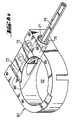
- Fig. 6 shows a schematic perspective view of an embodiment of a system according to the invention for mechanically coupling a macroactuator 41, e.g. a piezo disk translator or any other type of macroactuator, to a membrane of a micromachined pipetting device, e.g. to the membrane 16 of a micromechanical pipetting device 11 of the type shown by Figures 1-5.
- a macroactuator 41 e.g. a piezo disk translator or any other type of macroactuator
- a membrane of a micromachined pipetting device e.g. to the membrane 16 of a micromechanical pipetting device 11 of the type shown by Figures 1-5.
- Fig. shows an exploded view of the components shown by Fig. 6.
- the coupling system comprises the following components:
- first body (51) has a substantially cylindrical shape, comprises a chamber (52) for receiving macroactuator 41, and a substantial part of macroactuator (41) is located in chamber (52) of first body (51).
- macroactuator 41 is any actuator which cannot be manufactured by a micromachining process and which is apt to exert on membrane 16 a force larger than one Newton and along a displacement of the membrane of about 10 micrometers or more.
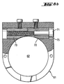
- the means for fixing the axial position of said first body 51 within said bore 62 of second body 61 comprise a first bolt segment 72 and a second bolt segment 73. These bolt segments 72, 73 are located within a bore 75 of second body 61. Each of bolt segments 72, 73 has a side wall which has the same radius of curvature as a closed line defined by a cross-section of bore 62 of second body 61. In a preferred embodiment said closed line is a circle.
- the means for fixing the axial position of said first body 51 within said bore 62 of second body 61 further comprise a screw 71 passing through bolt segment 72 and being connectable to bolt segment 73 by a screw connection, which is adapted to enable that bolt segments 72, 73 are pulled against each other by turning screw 71 with a screw driver 74 in order to reduce an initial gap existing between bolt segment 72 and bolt segment 73 and thereby reduce the space available for said first body 51 in bore 62 of second body 61.
- a further coupling system is described hereinafter with reference to Figures 9 and 10.
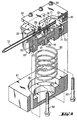
- This coupling system is based on the coupling system of the embodiment described above with reference to Fig. 6 and comprises additional means for adjusting with high accuracy the axial position of first body 51 in bore 62 of second body 61.
- Fig. 9 schematically shows a schematic perspective view of the embodiment shown by Fig. 6 and an exploded view of additional components of coupling means used for fixing with high precision the position of inner cylinder 51 in the bore 62 of outer cylinder 61.
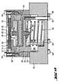
- Fig. 10 shows a cross-sectional view of the embodiment shown by Fig. 9 when the components shown therein are assembled.
- Fig. 10 illustrates the positioning of inner cylinder 51 in the bore of outer cylinder 61 by means of the additional components of coupling components shown by the lower half of Fig. 9.
- FIG. 12 A typical diagram of deflection of the center of a membrane of a micromechanical pipetting device versus pressure exerted on the membrane for causing said deflection is represented in Fig. 12.
- micromachined pipetting device is e.g. a micropipetting device 11 of the kind described with reference to Figures 1-5
- a large mono-crystalline (m-silicon) silicon membrane permits large deflections.
- the relaxation forces thereby increase progressively, i.e. the membrane behaves like a progressive spring with an over-proportional increase (that is with a proportionality factor larger than one) of the relaxation forces versus the deformation. Therefore, depending on the position of the actuator towards the actuator membrane , within the scope of the invention a different membrane pre-load is chosen. This offers the possibility to adjust the strength of the relaxation force over the actuation stroke, hence permits to find an optimized position for maximum membrane displacement and maximum membrane force, said optimized position being optimized between strong deformation force of the actuator and increasing relaxation force of the membrane.
- a pipetting module according to the invention comprises, among others, the following components shown by Figures 6 and 7:
- Micromachined pipetting device 11 is e.g. as described above with reference to Figures 1 to 5. Therefore, micromachined pipetting device 11 includes a membrane 16 formed by a silicon layer 14 arranged between an upper glass or silicon layer 26 and a lower glass or silicon layer 27, said lower glass or silicon layer 27 has a bore 19 which provides said macroactuator 41 access to the central part of said membrane 16.
- membrane 16 has a boss 24 in its central part.
- boss 24 in its central part. The advantage provided by the presence of boss 24 at the point of contact is that it ensures an optimum transmission of the actuation stroke and power.
- the means for mechanically coupling macroactuator 41 to membrane 16 are e.g. as described above with reference to Figures 6 to 10.
- a preferred embodiment of the means for mechanically coupling macroactuator 41 to membrane 16 further comprise means for mounting micromachined pipetting device 11 on second body 61, and the latter means comprise e.g. the following components:
- micromachined pipetting device 11 is arranged between clamping plate 31 and mounting plate 33 and is mounted with these plates on second body 61 e.g. by means of screws 34.
- the deflection of membrane 16 is effected with the coupled macroactuator 41.
- the actuator stroke on the membrane boss 24 determines the membrane deflection, hence the displaced volume.
- the displacement of membrane 16 is actively pushed by macroactuator 41.
- the relaxation forces of membrane 16 itself pull the membrane back to the initial position thereof determined by the actuator position. It is thus a passive actuation procedure.
- macroactuator 41 is any actuator which cannot be manufactured by a micromachining process and which is apt to exert on membrane 16 a force of at least one Newton and this along a membrane displacement of 10 micrometers or more. This capability of macroactuator 41 is advantageous in particular when the pipetting tip of micromechanical pipetting module 11 is relatively long and/or when the volume to be pipetted is relatively large.
- Fig. 11 shows a part of a pipetting unit including a pipetting module of the type described above and suitable for pipetting of biological liquids in the micro- and submicroliter range, in particular for industrial use in a commercial in-vitro diagnostics.
- a pipetting head 92 contains a pipetting module of the type described above and has a pipetting tip or needle 13.
- Pipetting head 92 is moved by means of a transport system 91 in three orthogonal directions X, Y, Z.
- Transport system 91 includes a transport bar 93 for transport in X-direction, a transport bar 94 for transport in Y-direction and means 95 for transport of pipetting head 92 in Z-direction.
- Transport system 91 is controlled by control means 96 which may e.g. be part of the control means of an automatic analyzer to which the pipetting unit shown by Fig. 11 belongs to. With this pipetting unit, pipetting operations can be effected e.g. on sample or reagent tubes 99 contained in racks 98 of an array 97 of racks.
- micromechanical pipetting module 11 all other components shown in Figures 6 and 7 are made e.g. of chromium steel or other suitable materials. These components can also be made e.g. of aluminum. Cap 42 be made e.g. of chromium steel, aluminum or yellow brass.
Landscapes
- Health & Medical Sciences (AREA)
- Chemical & Material Sciences (AREA)
- Clinical Laboratory Science (AREA)
- Chemical Kinetics & Catalysis (AREA)
- Immunology (AREA)
- Biochemistry (AREA)
- General Health & Medical Sciences (AREA)
- General Physics & Mathematics (AREA)
- Physics & Mathematics (AREA)
- Pathology (AREA)
- Analytical Chemistry (AREA)
- Life Sciences & Earth Sciences (AREA)
- Micromachines (AREA)
- Devices For Use In Laboratory Experiments (AREA)
- Fluid-Driven Valves (AREA)
- Sampling And Sample Adjustment (AREA)
- Feeding, Discharge, Calcimining, Fusing, And Gas-Generation Devices (AREA)
Claims (8)
- Module de pipettage comprenant :(a) un dispositif de pipettage micro usiné (11) pour pipeter des volumes de liquide dans la plage du sous microlitre et du microlitre, ledit dispositif de pipettage micro usiné (11) comprenant une membrane (16), la zone centrale de ladite membrane étant adaptée pour être déplacée par un macro actionneur, et(b) un macro actionneur (41) adapté pour effectuer ledit déplacement de ladite membrane (16),
caractérisé en ce qu'il comprend en outre(c) des moyens pour coupler mécaniquement ledit macro actionneur (41) à ladite membrane (16) dudit dispositif de pipettage micro usiné (11), lesdits moyens de couplage comprenant(d) un premier corps (51) adapté pour maintenir un macro actionneur, ledit premier corps (51) ayant une paroi latérale dotée d'une surface externe et d'un fond comprenant une surface externe,(e) un macro actionneur (41) qui possède une extrémité supérieure (45) et une extrémité inférieure (43), et qui est monté mécaniquement sur ledit premier corps (51),(f) un second corps (61) comprenant une surface externe supérieure, une surface externe inférieure, et un alésage (62) pour recevoir ledit premier corps (51), la taille dudit alésage (62) et la taille dudit premier corps (51) étant telles que la surface externe du premier corps (51) s'emboíte parfaitement à l'intérieur dudit alésage (62),(g) des moyens (71, 72, 73, 75) destinés à fixer la position axiale dudit premier corps (51) à l'intérieur dudit alésage (62), et(h) des moyens pour monter ledit dispositif micro usiné (11) sur ledit second corps (61) de sorte que l'extrémité supérieure (45) de l'actionneur exerce une force ou pression prédéterminée sur ladite membrane dudit dispositif micro usiné (11). - Module de pipettage selon la revendication 1, dans lequel ledit dispositif de pipettage micro usiné (11) possède une membrane (16) formée par une couche de silicium (14) agencée entre un verre supérieur ou couche de silicium (26) et un verre inférieur ou couche de silicium (27), ledit verre inférieur ou couche de silicium (27) possède un alésage (19) pour que ledit macro actionneur (41) ait accès à la partie centrale de ladite membrane (16).
- Module de pipettage selon la revendication 2, dans lequel ladite membrane (16) possède une protubérance (24) dans sa partie centrale.
- Module de pipettage selon la revendication 1, dans lequel ledit premier corps (51) a une forme sensiblement cylindrique et comprend une chambre (52) pour recevoir ledit macro actionneur, une partie essentielle dudit macro actionneur (41) étant située dans ladite chambre (52) dudit premier corps (51).
- Module de pipettage selon la revendication 1, dans lequel lesdits moyens (71, 72, 73) destinés à fixer la position axiale dudit premier corps (51) à l'intérieur dudit alésage (62) dudit second corps (61) comprennent :(i) un premier segment de boulon (72) et un second segment de boulon (73), lesdits segments de boulon (72, 73) étant situés à l'intérieur dudit second corps (61), et lesdits segments de boulon (72, 73) ayant chacun une paroi latérale ayant le même rayon de courbure qu'une ligne fermée définie par une section transversale dudit alésage (62) dudit second corps (61),(ii) une vis (71) passant à travers l'un des segments de boulon (72) et pouvant être raccordée à l'autre segment de boulon (73) par une connexion à vis, ladite connexion à vis étant adaptée pour permettre que lesdits segments de boulon (72, 73) soient poussés l'un contre l'autre afin de réduire la taille d'un espace existant entre lesdits segments de boulon (72, 73) et réduire ainsi l'espace disponible pour ledit premier corps (51) dans ledit alésage (62) dudit second corps (61).
- Module de pipettage selon la revendication 5, dans lequel ladite ligne fermée est un cercle.
- Module de pipettage selon la revendication 1, dans lequel lesdits moyens pour monter ledit dispositif de pipettage micro usiné (11) sur ledit second corps (61) comprennent :(i) une plaque de serrage (31) recouvrant le dispositif de pipettage micro usiné (11), et(ii) une plaque de montage (33) située au dessous du dispositif de pipettage micro usiné (11) et comprenant une fenêtre (32) donnant audit macro actionneur (41) accès à ladite membrane (16), ledit dispositif de pipettage micro usiné (11) étant agencé entre la plaque de serrage (31) et la plaque de montage (33) et étant monté avec ces plaques sur ledit second corps (61).
- Module de pipettage selon la revendication 1, dans lequel ledit dispositif de pipettage micro usiné (11) est un dispositif construit de manière solidaire qui possède une entrée/sortie (12) qui convient pour être raccordée à une pointe de pipettage amovible (13) ou est construit de manière solidaire avec une pointe de pipettage (13), ledit dispositif de pipettage micro usiné construit de manière solidaire (11) comprenant une structure micromécanique qui est construite de manière solidaire sur une plaquette de silicium (14) et qui comprend :a) une première chambre (15) située à l'intérieur dudit dispositif de pipettage micro usiné (11), le volume compris à l'intérieur de ladite première chambre (15) convenant pour être modifié par le déplacement d'une membrane (16) qui est une partie d'une paroi de ladite chambre (15), ladite première chambre (15) comprenant une ouverture (17), ladite ouverture étant ouverte en permanence et permettant l'écoulement de fluide dans et à partir de l'intérieur de ladite première chambre (15),b) un canal (18) situé à l'intérieur dudit dispositif de pipettage micro usiné (11), ledit canal (18) établissant un raccordement fluidique direct, sans soupape et permanent entre ladite ouverture (17) de la première chambre (15) et l'entrée/sortie (12) du dispositif de pipettage micro usiné (11),c) lesdits moyens de macro actionneur (41) étant adaptés pour provoquer un déplacement de la zone centrale de ladite membrane (16), et provoquer ainsi l'aspiration ou la distribution d'un volume d'air ou d'un liquide dans ou à partir de ladite première chambre (15), qui à son tour provoque l'aspiration ou la distribution d'un volume d'un échantillon liquide provenant respectivement de ladite pointe de pipettage (13).
Priority Applications (1)
| Application Number | Priority Date | Filing Date | Title |
|---|---|---|---|
| EP00988754A EP1232010B1 (fr) | 1999-11-26 | 2000-11-21 | Module de Pipettage comprenant un système de couplage d'un actionneur |
Applications Claiming Priority (4)
| Application Number | Priority Date | Filing Date | Title |
|---|---|---|---|
| EP99811094A EP1103305A1 (fr) | 1999-11-26 | 1999-11-26 | Système de couplage à un macroactionneur faisant partie d'un module de pipettage |
| EP99811094 | 1999-11-26 | ||
| PCT/EP2000/011693 WO2001037996A1 (fr) | 1999-11-26 | 2000-11-21 | Systeme de couplage d'un actionneur et module de pipettage le comprenant |
| EP00988754A EP1232010B1 (fr) | 1999-11-26 | 2000-11-21 | Module de Pipettage comprenant un système de couplage d'un actionneur |
Publications (2)
| Publication Number | Publication Date |
|---|---|
| EP1232010A1 EP1232010A1 (fr) | 2002-08-21 |
| EP1232010B1 true EP1232010B1 (fr) | 2004-05-12 |
Family
ID=8243164
Family Applications (2)
| Application Number | Title | Priority Date | Filing Date |
|---|---|---|---|
| EP99811094A Withdrawn EP1103305A1 (fr) | 1999-11-26 | 1999-11-26 | Système de couplage à un macroactionneur faisant partie d'un module de pipettage |
| EP00988754A Expired - Lifetime EP1232010B1 (fr) | 1999-11-26 | 2000-11-21 | Module de Pipettage comprenant un système de couplage d'un actionneur |
Family Applications Before (1)
| Application Number | Title | Priority Date | Filing Date |
|---|---|---|---|
| EP99811094A Withdrawn EP1103305A1 (fr) | 1999-11-26 | 1999-11-26 | Système de couplage à un macroactionneur faisant partie d'un module de pipettage |
Country Status (8)
| Country | Link |
|---|---|
| US (2) | US7125519B1 (fr) |
| EP (2) | EP1103305A1 (fr) |
| JP (1) | JP2003514659A (fr) |
| AT (1) | ATE266475T1 (fr) |
| CA (1) | CA2391509A1 (fr) |
| DE (1) | DE60010746T2 (fr) |
| ES (1) | ES2219434T3 (fr) |
| WO (1) | WO2001037996A1 (fr) |
Families Citing this family (8)
| Publication number | Priority date | Publication date | Assignee | Title |
|---|---|---|---|---|
| US7125727B2 (en) | 2003-01-29 | 2006-10-24 | Protedyne Corporation | Sample handling tool with piezoelectric actuator |
| GB0517910D0 (en) * | 2005-09-05 | 2005-10-12 | Enigma Diagnostics Ltd | Liquid transfer device |
| CN101881706B (zh) * | 2010-07-05 | 2014-04-02 | 深圳迈瑞生物医疗电子股份有限公司 | 一种采样设备及方法 |
| CN103429348B (zh) * | 2011-01-21 | 2016-03-09 | 拜奥-多特公司 | 具有纵向变换器和可替换毛细管的压电分配器 |
| US20140354734A1 (en) * | 2013-06-04 | 2014-12-04 | The Regents Of The University Of California | Non-contact bio-printing |
| EP3924107A4 (fr) * | 2019-02-15 | 2022-10-05 | Cellsorter Kft. | Micro-pipette piézoélectrique |
| WO2020214224A1 (fr) * | 2019-04-18 | 2020-10-22 | Siemens Healthcare Diagnostics Inc. | Dispositif microfluidique intégré avec adaptation de pipette |
| CN116212747B (zh) * | 2022-12-29 | 2025-09-23 | 杭州联川生物技术股份有限公司 | 一种高密度阵列式加液喷头模块 |
Citations (3)
| Publication number | Priority date | Publication date | Assignee | Title |
|---|---|---|---|---|
| US5676531A (en) * | 1996-03-21 | 1997-10-14 | Pulsafeeder, Inc. | Autoclavable pump head assembly |
| US5741976A (en) * | 1995-06-06 | 1998-04-21 | Firschungszeutrwm Karlsruhe Gmbh | Apparatus for the single-axis examination of micro-tension samples |
| WO1999046576A1 (fr) * | 1998-03-11 | 1999-09-16 | E.I. Du Pont De Nemours And Company | Dispositif de test et technique de mesure de la resistance aux eraflures d'un film ou d'un revetement |
Family Cites Families (11)
| Publication number | Priority date | Publication date | Assignee | Title |
|---|---|---|---|---|
| US4303376A (en) * | 1979-07-09 | 1981-12-01 | Baxter Travenol Laboratories, Inc. | Flow metering cassette and controller |
| US4379681A (en) * | 1980-01-04 | 1983-04-12 | Paul R. Goudy, Jr. | Fluid pump with dual diaphragm check valves |
| WO1988000708A1 (fr) * | 1986-07-21 | 1988-01-28 | Ilex Corporation | Analyseur utilise en chimie clinique |
| US4803393A (en) * | 1986-07-31 | 1989-02-07 | Toyota Jidosha Kabushiki Kaisha | Piezoelectric actuator |
| JP3373558B2 (ja) * | 1992-04-23 | 2003-02-04 | 松下電工株式会社 | 小型ポンプ装置 |
| SG44800A1 (en) * | 1993-12-28 | 1997-12-19 | Westonbridge Int Ltd | A micropump |
| DE4419638C2 (de) * | 1994-06-04 | 1996-06-13 | Eppendorf Geraetebau Netheler | Pipettiereinrichtung für sehr kleine Volumina |
| GB9521775D0 (en) * | 1995-10-24 | 1996-01-03 | Pa Consulting Services | Microwell plates |
| US5863801A (en) * | 1996-06-14 | 1999-01-26 | Sarnoff Corporation | Automated nucleic acid isolation |
| EP0865824B1 (fr) * | 1997-03-20 | 2004-05-19 | F. Hoffmann-La Roche Ag | Dispositif de pipetage micromécanique |
| US6074611A (en) | 1997-04-28 | 2000-06-13 | Apogee Designs, Ltd. | Micro-pipettor apparatus |
-
1999
- 1999-11-26 EP EP99811094A patent/EP1103305A1/fr not_active Withdrawn
-
2000
- 2000-11-21 CA CA002391509A patent/CA2391509A1/fr not_active Abandoned
- 2000-11-21 DE DE60010746T patent/DE60010746T2/de not_active Expired - Fee Related
- 2000-11-21 US US10/148,149 patent/US7125519B1/en not_active Expired - Fee Related
- 2000-11-21 EP EP00988754A patent/EP1232010B1/fr not_active Expired - Lifetime
- 2000-11-21 WO PCT/EP2000/011693 patent/WO2001037996A1/fr not_active Ceased
- 2000-11-21 ES ES00988754T patent/ES2219434T3/es not_active Expired - Lifetime
- 2000-11-21 AT AT00988754T patent/ATE266475T1/de not_active IP Right Cessation
- 2000-11-21 JP JP2001539598A patent/JP2003514659A/ja active Pending
-
2006
- 2006-08-22 US US11/466,336 patent/US20060281213A1/en not_active Abandoned
Patent Citations (3)
| Publication number | Priority date | Publication date | Assignee | Title |
|---|---|---|---|---|
| US5741976A (en) * | 1995-06-06 | 1998-04-21 | Firschungszeutrwm Karlsruhe Gmbh | Apparatus for the single-axis examination of micro-tension samples |
| US5676531A (en) * | 1996-03-21 | 1997-10-14 | Pulsafeeder, Inc. | Autoclavable pump head assembly |
| WO1999046576A1 (fr) * | 1998-03-11 | 1999-09-16 | E.I. Du Pont De Nemours And Company | Dispositif de test et technique de mesure de la resistance aux eraflures d'un film ou d'un revetement |
Also Published As
| Publication number | Publication date |
|---|---|
| US20060281213A1 (en) | 2006-12-14 |
| JP2003514659A (ja) | 2003-04-22 |
| DE60010746T2 (de) | 2005-05-04 |
| ATE266475T1 (de) | 2004-05-15 |
| CA2391509A1 (fr) | 2001-05-31 |
| WO2001037996A1 (fr) | 2001-05-31 |
| ES2219434T3 (es) | 2004-12-01 |
| DE60010746D1 (de) | 2004-06-17 |
| EP1232010A1 (fr) | 2002-08-21 |
| US7125519B1 (en) | 2006-10-24 |
| EP1103305A1 (fr) | 2001-05-30 |
Similar Documents
| Publication | Publication Date | Title |
|---|---|---|
| Laurell et al. | Design and development of a silicon microfabricated flow-through dispenser for on-line picolitre sample handling | |
| EP0835435B1 (fr) | Cellule d'echantillonnage a ecoulement continu et son utilisation | |
| US7618590B2 (en) | Fluid dispensing system | |
| US6232129B1 (en) | Piezoelectric pipetting device | |
| US7258253B2 (en) | Method and system for precise dispensation of a liquid | |
| US20020168297A1 (en) | Method and device for dispensing of droplets | |
| EP1232010B1 (fr) | Module de Pipettage comprenant un système de couplage d'un actionneur | |
| US20030202907A1 (en) | Dispensing method and apparatus for dispensing very small quantities of fluid | |
| EP0865824B1 (fr) | Dispositif de pipetage micromécanique | |
| WO1996024040A2 (fr) | Micropipette a commande electrique | |
| WO2001056695A1 (fr) | Tete de pipette multicanaux pour appareil de prelevement a la pipette | |
| US6599477B1 (en) | Chemical analysis apparatus | |
| WO1998037397A1 (fr) | Dispositif de melange commande par actionneur piezo-ceramique | |
| US7055723B2 (en) | Device and system for dispensing or aspirating/dispensing liquid samples | |
| Szita et al. | A micropipettor with integrated sensors | |
| US7526968B2 (en) | Device for pipetting a liquid | |
| JP7320864B2 (ja) | 圧電マイクロピペット | |
| Szita et al. | A fast and low-volume pipettor with integrated sensors for high precision | |
| Szita et al. | Aspiration and dispensing of biological liquids in the micro-and submicroliter range with high precision | |
| Szita et al. | Pneumatically actuated micropipetting device | |
| Taylor et al. | Microfluidic bioanalysis cartridge with interchangeable microchannel separation components |
Legal Events
| Date | Code | Title | Description |
|---|---|---|---|
| PUAI | Public reference made under article 153(3) epc to a published international application that has entered the european phase |
Free format text: ORIGINAL CODE: 0009012 |
|
| 17P | Request for examination filed |
Effective date: 20020325 |
|
| AK | Designated contracting states |
Kind code of ref document: A1 Designated state(s): AT BE CH CY DE DK ES FI FR GB GR IE IT LI LU MC NL PT SE TR |
|
| AX | Request for extension of the european patent |
Free format text: AL;LT;LV;MK;RO;SI |
|
| RIN1 | Information on inventor provided before grant (corrected) |
Inventor name: SZITA, NICOLAS Inventor name: ELSENHANS, OLIVIER Inventor name: BUSER, RUDOLF |
|
| 17Q | First examination report despatched |
Effective date: 20030401 |
|
| GRAP | Despatch of communication of intention to grant a patent |
Free format text: ORIGINAL CODE: EPIDOSNIGR1 |
|
| RTI1 | Title (correction) |
Free format text: A PIPETTING MODULE COMPRISING AN ACTUATOR COUPLING SYSTEM |
|
| GRAS | Grant fee paid |
Free format text: ORIGINAL CODE: EPIDOSNIGR3 |
|
| GRAA | (expected) grant |
Free format text: ORIGINAL CODE: 0009210 |
|
| AK | Designated contracting states |
Kind code of ref document: B1 Designated state(s): AT BE CH CY DE DK ES FI FR GB GR IE IT LI LU MC NL PT SE TR |
|
| PG25 | Lapsed in a contracting state [announced via postgrant information from national office to epo] |
Ref country code: NL Free format text: LAPSE BECAUSE OF FAILURE TO SUBMIT A TRANSLATION OF THE DESCRIPTION OR TO PAY THE FEE WITHIN THE PRESCRIBED TIME-LIMIT Effective date: 20040512 Ref country code: FI Free format text: LAPSE BECAUSE OF FAILURE TO SUBMIT A TRANSLATION OF THE DESCRIPTION OR TO PAY THE FEE WITHIN THE PRESCRIBED TIME-LIMIT Effective date: 20040512 Ref country code: TR Free format text: LAPSE BECAUSE OF FAILURE TO SUBMIT A TRANSLATION OF THE DESCRIPTION OR TO PAY THE FEE WITHIN THE PRESCRIBED TIME-LIMIT Effective date: 20040512 Ref country code: CY Free format text: LAPSE BECAUSE OF FAILURE TO SUBMIT A TRANSLATION OF THE DESCRIPTION OR TO PAY THE FEE WITHIN THE PRESCRIBED TIME-LIMIT Effective date: 20040512 Ref country code: BE Free format text: LAPSE BECAUSE OF FAILURE TO SUBMIT A TRANSLATION OF THE DESCRIPTION OR TO PAY THE FEE WITHIN THE PRESCRIBED TIME-LIMIT Effective date: 20040512 |
|
| REG | Reference to a national code |
Ref country code: GB Ref legal event code: FG4D |
|
| REG | Reference to a national code |
Ref country code: CH Ref legal event code: EP |
|
| REG | Reference to a national code |
Ref country code: IE Ref legal event code: FG4D |
|
| REF | Corresponds to: |
Ref document number: 60010746 Country of ref document: DE Date of ref document: 20040617 Kind code of ref document: P |
|
| REG | Reference to a national code |
Ref country code: CH Ref legal event code: NV Representative=s name: VENTOCILLA PATENT AG |
|
| PG25 | Lapsed in a contracting state [announced via postgrant information from national office to epo] |
Ref country code: DK Free format text: LAPSE BECAUSE OF FAILURE TO SUBMIT A TRANSLATION OF THE DESCRIPTION OR TO PAY THE FEE WITHIN THE PRESCRIBED TIME-LIMIT Effective date: 20040812 Ref country code: GR Free format text: LAPSE BECAUSE OF FAILURE TO SUBMIT A TRANSLATION OF THE DESCRIPTION OR TO PAY THE FEE WITHIN THE PRESCRIBED TIME-LIMIT Effective date: 20040812 Ref country code: SE Free format text: LAPSE BECAUSE OF FAILURE TO SUBMIT A TRANSLATION OF THE DESCRIPTION OR TO PAY THE FEE WITHIN THE PRESCRIBED TIME-LIMIT Effective date: 20040812 |
|
| LTIE | Lt: invalidation of european patent or patent extension |
Effective date: 20040512 |
|
| NLV1 | Nl: lapsed or annulled due to failure to fulfill the requirements of art. 29p and 29m of the patents act | ||
| PG25 | Lapsed in a contracting state [announced via postgrant information from national office to epo] |
Ref country code: LU Free format text: LAPSE BECAUSE OF NON-PAYMENT OF DUE FEES Effective date: 20041121 |
|
| PG25 | Lapsed in a contracting state [announced via postgrant information from national office to epo] |
Ref country code: IE Free format text: LAPSE BECAUSE OF NON-PAYMENT OF DUE FEES Effective date: 20041122 |
|
| PG25 | Lapsed in a contracting state [announced via postgrant information from national office to epo] |
Ref country code: MC Free format text: LAPSE BECAUSE OF NON-PAYMENT OF DUE FEES Effective date: 20041130 |
|
| REG | Reference to a national code |
Ref country code: ES Ref legal event code: FG2A Ref document number: 2219434 Country of ref document: ES Kind code of ref document: T3 |
|
| ET | Fr: translation filed | ||
| PLBE | No opposition filed within time limit |
Free format text: ORIGINAL CODE: 0009261 |
|
| STAA | Information on the status of an ep patent application or granted ep patent |
Free format text: STATUS: NO OPPOSITION FILED WITHIN TIME LIMIT |
|
| 26N | No opposition filed |
Effective date: 20050215 |
|
| REG | Reference to a national code |
Ref country code: IE Ref legal event code: MM4A |
|
| PGFP | Annual fee paid to national office [announced via postgrant information from national office to epo] |
Ref country code: GB Payment date: 20061004 Year of fee payment: 7 |
|
| PGFP | Annual fee paid to national office [announced via postgrant information from national office to epo] |
Ref country code: AT Payment date: 20061005 Year of fee payment: 7 |
|
| PGFP | Annual fee paid to national office [announced via postgrant information from national office to epo] |
Ref country code: CH Payment date: 20061026 Year of fee payment: 7 |
|
| PGFP | Annual fee paid to national office [announced via postgrant information from national office to epo] |
Ref country code: FR Payment date: 20061103 Year of fee payment: 7 |
|
| PGFP | Annual fee paid to national office [announced via postgrant information from national office to epo] |
Ref country code: ES Payment date: 20061120 Year of fee payment: 7 |
|
| PGFP | Annual fee paid to national office [announced via postgrant information from national office to epo] |
Ref country code: DE Payment date: 20061130 Year of fee payment: 7 Ref country code: IT Payment date: 20061130 Year of fee payment: 7 |
|
| PG25 | Lapsed in a contracting state [announced via postgrant information from national office to epo] |
Ref country code: PT Free format text: LAPSE BECAUSE OF NON-PAYMENT OF DUE FEES Effective date: 20041012 |
|
| GBPC | Gb: european patent ceased through non-payment of renewal fee |
Effective date: 20071121 |
|
| PG25 | Lapsed in a contracting state [announced via postgrant information from national office to epo] |
Ref country code: LI Free format text: LAPSE BECAUSE OF NON-PAYMENT OF DUE FEES Effective date: 20071130 Ref country code: CH Free format text: LAPSE BECAUSE OF NON-PAYMENT OF DUE FEES Effective date: 20071130 |
|
| REG | Reference to a national code |
Ref country code: CH Ref legal event code: PL |
|
| PG25 | Lapsed in a contracting state [announced via postgrant information from national office to epo] |
Ref country code: AT Free format text: LAPSE BECAUSE OF NON-PAYMENT OF DUE FEES Effective date: 20071121 |
|
| PG25 | Lapsed in a contracting state [announced via postgrant information from national office to epo] |
Ref country code: DE Free format text: LAPSE BECAUSE OF NON-PAYMENT OF DUE FEES Effective date: 20080603 |
|
| REG | Reference to a national code |
Ref country code: FR Ref legal event code: ST Effective date: 20080930 |
|
| PG25 | Lapsed in a contracting state [announced via postgrant information from national office to epo] |
Ref country code: GB Free format text: LAPSE BECAUSE OF NON-PAYMENT OF DUE FEES Effective date: 20071121 |
|
| REG | Reference to a national code |
Ref country code: ES Ref legal event code: FD2A Effective date: 20071122 |
|
| PG25 | Lapsed in a contracting state [announced via postgrant information from national office to epo] |
Ref country code: ES Free format text: LAPSE BECAUSE OF NON-PAYMENT OF DUE FEES Effective date: 20071122 Ref country code: FR Free format text: LAPSE BECAUSE OF NON-PAYMENT OF DUE FEES Effective date: 20071130 |
|
| PG25 | Lapsed in a contracting state [announced via postgrant information from national office to epo] |
Ref country code: IT Free format text: LAPSE BECAUSE OF NON-PAYMENT OF DUE FEES Effective date: 20071121 |