EP1232705A2 - Système de securité à crochet et potence - Google Patents
Système de securité à crochet et potence Download PDFInfo
- Publication number
- EP1232705A2 EP1232705A2 EP02250902A EP02250902A EP1232705A2 EP 1232705 A2 EP1232705 A2 EP 1232705A2 EP 02250902 A EP02250902 A EP 02250902A EP 02250902 A EP02250902 A EP 02250902A EP 1232705 A2 EP1232705 A2 EP 1232705A2
- Authority
- EP
- European Patent Office
- Prior art keywords
- hook
- component
- bracket
- security assembly
- assembly according
- Prior art date
- Legal status (The legal status is an assumption and is not a legal conclusion. Google has not performed a legal analysis and makes no representation as to the accuracy of the status listed.)
- Withdrawn
Links
Images


Classifications
-
- A—HUMAN NECESSITIES
- A47—FURNITURE; DOMESTIC ARTICLES OR APPLIANCES; COFFEE MILLS; SPICE MILLS; SUCTION CLEANERS IN GENERAL
- A47F—SPECIAL FURNITURE, FITTINGS, OR ACCESSORIES FOR SHOPS, STOREHOUSES, BARS, RESTAURANTS OR THE LIKE; PAYING COUNTERS
- A47F5/00—Show stands, hangers, or shelves characterised by their constructional features
- A47F5/08—Show stands, hangers, or shelves characterised by their constructional features secured to the wall, ceiling, or the like; Wall-bracket display devices
- A47F5/0807—Display panels, grids or rods used for suspending merchandise or cards supporting articles; Movable brackets therefor
- A47F5/0861—Anti-theft means therefor
Definitions
- This invention concerns a security assembly for suspended items on display.
- a hook of a type which comprises an elongate finger-like projection attached to an upright supporting surface, such as a wall or a partition panel. Items displayed in this way are usually packed in a transparent plastics casing, commonly known as a "bubble pack", which is provided with an aperture through which the hook is inserted. A series of identical items are generally suspended in this way one in front of the other on a common hook.
- Slat wall lining is a commercially available style of wall panelling wherein each panel is provided with a plurality of equally spaced parallel slots of L-shaped cross-section which in use are intended to be arranged horizontally. Brackets having angled edge margins can then be retained by insertion of said edge margins at selected positions in any of the L-shaped slots (i.e. at any chosen height interval). They are retained simply by abutment with the walls of the slot and by gravity and can readily be removed and repositioned. Hooks for suspension of items for sale are attached to or formed integrally with such brackets.
- An object of the invention is to provide means whereby items to be displayed can be securely retained upon hooks which are mounted upon such slat wall lining.
- a security assembly for suspended items on display comprises a bracket provided with a hook, the bracket having means for engagement in a slot of a slat wall lining, a second component, also having means for engagement in a slot of the slat wall lining, and connector means engageable with the hook whereby the second component and the bracket, when engaged with adjacent slots of the slat wall lining, may be connected together and clamped between said adjacent slots so that neither is removable therefrom.
- the connector means are provided on a separate connector component.
- the connector means may be provided on the second component, for example, in the form of a plastic strap which is threaded through apertures in the second component, looped around the hook, and secured to itself in conventional manner.
- the second component may have an additional flange provided with the apertures for the strap.
- the aforesaid lock body may also be provided with a slot, or other attachment means, to facilitate attachment of sales indicia relative to the items suspended from the hook.
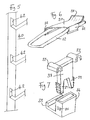
- a first embodiment comprises four components, namely a bracket (10) provided with a hook (12), a second component (16), a connector component (18), and a locking device (19).
- the bracket (10) is equivalent to a known slat wall mounting bracket (often called a "Eurohook"). It is formed of a sheet of metal or plastics material which is bent or formed into an L-shape along an edge margin (14).
- the hook (12) is a wire loop which is permanently attached near the centre of the bracket (10) extending outwards generally at right angles to the sheet.
- the L-shaped margin (14) is of a shape and size corresponding to a slot (42) of a slat wall lining panel (40), as shown in Figure 5, so that it can be located therein and will allow the first bracket (10) to be retained hanging down from that slot (42).
- a conventional "Eurohook” bracket would be readily detachable from the slot (42) from which it was suspended.
- the purpose of the assembly of the present invention is to prevent that.
- the second component (16) is also formed of a sheet of metal or plastics material which is bent into an L-shape along an edge margin (13). However, this L-shape margin (13) is turned inwards to provide a channel, in contrast to the margin (14) of the bracket (10). The opposing edge to the channel (13) has an upstanding tab (15) at a central location with a folded or hooked edge (17).
- edge margin (14) of the bracket (10) is located in a slot (42).
- the channel (13) of the second component (16) is inserted into the slot therebelow and the tab (15) then projects between the limbs of the wire hook (12), as shown in Fig 2.
- the connector (18) is a piece of stainless steel sheet of approximately 1 ⁇ 2 mm thickness provided with a curving spring portion (20) at one end and four arms (21-24), two at each side, which can be manually folded and crimped. In use, this is positioned on top of the hook (12), as shown in Fig 3, with the spring portion (20) locating into the hooked edge (17) of the second component (16). This is important in order to bias the second component (16) upwards and retain its channel (13) in the lower L-shaped slot (42), in other words to retain the bracket (10) and the component (16) in engagement with the respective pair of slots (42).
- the arms (21-24) are folded around and pressed onto the limbs of the hook (12), as indicated by the arrows in Fig 3, to hold the spring portion (20) in position.
- the inter-engaged bracket (10) and lower component (16) may still be capable of being slid along the slat wall lining, but cannot be demounted to the front without disconnecting the connector (18).
- a conventional padlock may be secured at or near the other end of the hook (12) to prevent their removal. The presence of the items makes access to the connector (18) difficult, thus minimising likelihood of theft by its removal.
- FIG. 1 An alternative to a conventional padlock is the locking device (19) which is shown in Figs. 1 and 3.
- This device (19) may comprise a conventional padlock onto which a special casing or sleeve (25) is mounted so that the padlock provides its conventional locking arm (45) securable to the body of the device, while the casing provides an additional arm (41) to one side of the securable arm (45).
- this modified device (19) can be mounted transversely of the hook (12), as is evident in Fig. 3, with the extra arm (41) engaged over the other loop of the hook (12), its free end not being secured.
- a further appendage (43) on the front of the casing (25) forms a slot and provides a rail which allows for attachment of sales indicia, such as price information regarding the items (not shown) suspended from the hook (12).
- This locking device (19) is a novel feature in its own right and could be used with any hook of this style, separate from the remainder of the security assembly.
- Other versions could be specifically fabricated, but it is probably easier and cost effective just to add a casing provided with a free arm (41) to a commercially available padlock.
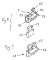
- FIGS 8 and 9 show a slightly modified version (49) of such a locking device.
- This comprises a conventional padlock (50) and a sheath or casing (51), which fits over the padlock (50), but is wider. It is preferably formed of plastics material.
- This sheath (51) has a recess (52) into which the body of the padlock (50) is a snug fit, and a slot (53) in the top of the recess (52) is provided for the securable locking arm (57) of the padlock (50) to project through.
- a hooked arm (55) projects upwards therefrom.
- This arm (55) curls towards the recess (52), whereas the arm (41) of the device (19) shown in Figs. 1 and 3 curls away.
- the configuration of the arm (41), (55) should be chosen according to ergonomic criteria, as to what best fits onto a display hook (12) and suspends the device (19), (49) in a well-balanced manner.
- a rail (56) is provided for attachment of sales indicia.
- Fig 4 shows an alternative to the security assembly of Figs. 1 to 3 where the hook is a flat strip (27) and a pair of tabs (28), each having a hooked edge (29), project up from the second component (26) to locate at either side of the hook (27).
- the assembly may be as in Figs 1 to 3 or as in Fig 6, although the locking device (19 or 49) will not be securable to such a hook.
- Fig 6 shows another alternative wherein the connector component is a clip device (30) having opposing engagement means (32) to clip around the sides of the hook (12), whether of wire loop form, as shown, or in the form of a flat strip, as in Fig 4, instead of having deformable arms (21-24).
- the clip device (30) still has an upturned spring portion (31) to engage and bias the second component, which can be substantially as shown in Figs 1 to 3.
- Another version (not shown) of clippable connector device may clip in between the limbs of a wire loop hook.
- Fig 7 illustrates a different form of assembly, still within the scope of the invention.
- the bracket and hook are as shown in Figs 1 to 3 and are not illustrated again.
- the second component (36) is of narrow box section form, with an L-shaped external flange (33) to fit into the slot (42) of the slat wall lining (40).
- the box section part lies beneath the hook (12).
- a connector element (38) is inserted between the limbs of the hook (12) from above to interconnect with the box section part.
- An arched flange (37) at each side of the connector element (38) engages around the respective limbs of the hook (12), and resilient barbed prongs (39) engage into the box section cavity.
- One or more of the barbs clip into apertures (35) in the sides of the box section and may be released therefrom using a tool.
- Another particular advantage of having multiple barbs on the prongs (39) is that this accommodates variations which occur in conventional, pre-existing slat wall lining and Eurohooks, to which the invention is to be applied.
- the spacing between the horizontal slots (42) in the lining (40) (Fig.5) may vary, and this can be accommodated by engagement of higher or lower barbs in the box section apertures.
- the position of the hook (12) may vary, as regards its height on the bracket (10) and again this can be accommodated by engagement of higher or lower barbs with the second component.
- a separator connector device as embodied by devices 18, 30 and 38 above may not always be necessary and other embodiments are envisaged where the connector means is provided directly upon or integrally with the second component.
- the connector means is provided directly upon or integrally with the second component.
- resilient barbs could be provided on the tabs (15,28) to directly engage with the sides of the respective hook (12, 27).
Landscapes
- Supports Or Holders For Household Use (AREA)
- Hooks, Suction Cups, And Attachment By Adhesive Means (AREA)
- Connection Of Plates (AREA)
Applications Claiming Priority (2)
| Application Number | Priority Date | Filing Date | Title |
|---|---|---|---|
| GB0103938A GB0103938D0 (en) | 2001-02-17 | 2001-02-17 | Hook and bracket security assembly |
| GB0103938 | 2001-02-17 |
Publications (2)
| Publication Number | Publication Date |
|---|---|
| EP1232705A2 true EP1232705A2 (fr) | 2002-08-21 |
| EP1232705A3 EP1232705A3 (fr) | 2003-12-10 |
Family
ID=9908954
Family Applications (1)
| Application Number | Title | Priority Date | Filing Date |
|---|---|---|---|
| EP02250902A Withdrawn EP1232705A3 (fr) | 2001-02-17 | 2002-02-09 | Système de securité à crochet et potence |
Country Status (2)
| Country | Link |
|---|---|
| EP (1) | EP1232705A3 (fr) |
| GB (2) | GB0103938D0 (fr) |
Cited By (2)
| Publication number | Priority date | Publication date | Assignee | Title |
|---|---|---|---|---|
| US10231556B2 (en) | 2012-11-20 | 2019-03-19 | Ccl Label, Inc. | Wall mount organization system |
| US12036660B2 (en) | 2020-08-07 | 2024-07-16 | Techtronic Cordless Gp | Modular storage system |
Family Cites Families (5)
| Publication number | Priority date | Publication date | Assignee | Title |
|---|---|---|---|---|
| US3545711A (en) * | 1969-02-25 | 1970-12-08 | Henry F Scheneman | Support bracket for engagement with perforate panels |
| US4678151A (en) * | 1984-06-29 | 1987-07-07 | Ready Metal Manufacturing Company | Merchandise hanger for slotted wall display panel |
| GB2250180B (en) * | 1990-11-28 | 1993-05-26 | Barrie Edward Ford | Support system |
| GB2309155B (en) * | 1996-01-17 | 1999-10-13 | Josef Benedict Kopieczek | Point of sale systems |
| US6003685A (en) * | 1997-11-14 | 1999-12-21 | Frank Mayer & Associates, Inc. | Peg board hook and security lock assembly |
-
2001
- 2001-02-17 GB GB0103938A patent/GB0103938D0/en not_active Ceased
-
2002
- 2002-02-09 EP EP02250902A patent/EP1232705A3/fr not_active Withdrawn
- 2002-02-11 GB GB0203068A patent/GB2374519B/en not_active Expired - Fee Related
Cited By (2)
| Publication number | Priority date | Publication date | Assignee | Title |
|---|---|---|---|---|
| US10231556B2 (en) | 2012-11-20 | 2019-03-19 | Ccl Label, Inc. | Wall mount organization system |
| US12036660B2 (en) | 2020-08-07 | 2024-07-16 | Techtronic Cordless Gp | Modular storage system |
Also Published As
| Publication number | Publication date |
|---|---|
| GB0203068D0 (en) | 2002-03-27 |
| EP1232705A3 (fr) | 2003-12-10 |
| GB2374519B (en) | 2004-05-12 |
| GB2374519A (en) | 2002-10-23 |
| GB0103938D0 (en) | 2001-04-04 |
Similar Documents
| Publication | Publication Date | Title |
|---|---|---|
| US6202865B1 (en) | Sample and tool displaying board | |
| US4319731A (en) | Merchandise display assembly | |
| US7673759B2 (en) | Dinnerware display | |
| EP0722158B1 (fr) | Dispositif de montage d'un affichage de prix | |
| US6092656A (en) | Wrench socket holder with locking member | |
| US4573590A (en) | Clip strip display unit | |
| US20050166438A1 (en) | Clip-on label holder for shelf channel | |
| US20090321595A1 (en) | Shelf front display mount | |
| US9186001B2 (en) | Offset hanger for minimizing space between frame and wall | |
| US20020125387A1 (en) | Device for hanging articles | |
| CA1280895C (fr) | Monture de porte-etiquette sur rive d'etagere | |
| US4258892A (en) | Peg hook display supporting apparatus | |
| JP4612026B2 (ja) | カード製品ディスプレイシステム | |
| US8132347B2 (en) | Interchangeable label holder | |
| CA2385284C (fr) | Porte-etiquette avec porte-affiche amovible | |
| US4697710A (en) | Carpet display stand | |
| CA2406326A1 (fr) | Presentoir et support pour montres | |
| US20050218280A1 (en) | Scanner plate hook and hook back plate for perforated boards | |
| EP1232705A2 (fr) | Système de securité à crochet et potence | |
| KR200442741Y1 (ko) | 벽걸이 제품의 벽면 고정구조 | |
| US20220000284A1 (en) | Pegboard Hanger Assembly | |
| US6767234B1 (en) | Hook and hang display system with plug-in bullnose header module | |
| JP2005204824A (ja) | カードホルダ及びその取付け構造 | |
| US20200288879A1 (en) | Pegboard Hanger Assembly | |
| GB2395107A (en) | Locking device for a display hook |
Legal Events
| Date | Code | Title | Description |
|---|---|---|---|
| PUAI | Public reference made under article 153(3) epc to a published international application that has entered the european phase |
Free format text: ORIGINAL CODE: 0009012 |
|
| AK | Designated contracting states |
Kind code of ref document: A2 Designated state(s): AT BE CH CY DE DK ES FI FR GB GR IE IT LI LU MC NL PT SE TR |
|
| AX | Request for extension of the european patent |
Free format text: AL;LT;LV;MK;RO;SI |
|
| PUAL | Search report despatched |
Free format text: ORIGINAL CODE: 0009013 |
|
| AK | Designated contracting states |
Kind code of ref document: A3 Designated state(s): AT BE CH CY DE DK ES FI FR GB GR IE IT LI LU MC NL PT SE TR |
|
| AX | Request for extension of the european patent |
Extension state: AL LT LV MK RO SI |
|
| AKX | Designation fees paid | ||
| REG | Reference to a national code |
Ref country code: DE Ref legal event code: 8566 |
|
| STAA | Information on the status of an ep patent application or granted ep patent |
Free format text: STATUS: THE APPLICATION IS DEEMED TO BE WITHDRAWN |
|
| 18D | Application deemed to be withdrawn |
Effective date: 20040611 |