EP1232731B1 - Zahnärztliches Handstück mit verbesserter Spannvorrichtung - Google Patents
Zahnärztliches Handstück mit verbesserter Spannvorrichtung Download PDFInfo
- Publication number
- EP1232731B1 EP1232731B1 EP01103883A EP01103883A EP1232731B1 EP 1232731 B1 EP1232731 B1 EP 1232731B1 EP 01103883 A EP01103883 A EP 01103883A EP 01103883 A EP01103883 A EP 01103883A EP 1232731 B1 EP1232731 B1 EP 1232731B1
- Authority
- EP
- European Patent Office
- Prior art keywords
- collet
- actuator
- spindle
- proximal end
- workpiece
- Prior art date
- Legal status (The legal status is an assumption and is not a legal conclusion. Google has not performed a legal analysis and makes no representation as to the accuracy of the status listed.)
- Expired - Lifetime
Links
- 230000006835 compression Effects 0.000 claims description 15
- 238000007906 compression Methods 0.000 claims description 15
- 230000004044 response Effects 0.000 claims description 6
- 238000005381 potential energy Methods 0.000 description 2
- 230000000717 retained effect Effects 0.000 description 2
- 230000020347 spindle assembly Effects 0.000 description 2
- 229910000639 Spring steel Inorganic materials 0.000 description 1
- 229910000831 Steel Inorganic materials 0.000 description 1
- 238000004140 cleaning Methods 0.000 description 1
- 230000001419 dependent effect Effects 0.000 description 1
- 230000000994 depressogenic effect Effects 0.000 description 1
- 230000000694 effects Effects 0.000 description 1
- 230000037431 insertion Effects 0.000 description 1
- 238000003780 insertion Methods 0.000 description 1
- 239000010959 steel Substances 0.000 description 1
Images


Classifications
-
- A—HUMAN NECESSITIES
- A61—MEDICAL OR VETERINARY SCIENCE; HYGIENE
- A61C—DENTISTRY; APPARATUS OR METHODS FOR ORAL OR DENTAL HYGIENE
- A61C1/00—Dental machines for boring or cutting ; General features of dental machines or apparatus, e.g. hand-piece design
- A61C1/08—Machine parts specially adapted for dentistry
- A61C1/14—Tool-holders, i.e. operating tool holders, e.g. burr holders
- A61C1/142—Operating tool blocking means
- A61C1/144—Operating tool blocking means constricting the operating tool, e.g. chuck
-
- A—HUMAN NECESSITIES
- A61—MEDICAL OR VETERINARY SCIENCE; HYGIENE
- A61C—DENTISTRY; APPARATUS OR METHODS FOR ORAL OR DENTAL HYGIENE
- A61C1/00—Dental machines for boring or cutting ; General features of dental machines or apparatus, e.g. hand-piece design
- A61C1/08—Machine parts specially adapted for dentistry
- A61C1/14—Tool-holders, i.e. operating tool holders, e.g. burr holders
Definitions
- This invention relates to a dental handpiece for retaining a conventional dental bur or similar workpiece and to an improved release means by which the bur can be easily removed from the handpiece while minimizing the manual pushing force that is necessary to actuate the release means.
- Compressed air driven dental handpieces have long been used by dental workers to treat the teeth of their patients.
- One of a variety of workpieces e.g. a dental bur
- a hollow cylindrical collet of the handpiece so as to be rotatable in response to a corresponding rotational force that is applied to the collet.
- the dental worker typically exerts a pushing force against a push-button of the handpiece which is ultimately transmitted to the collet so as to cause the collet to release its grip on the bur.
- a large pushing force is often required before the bur will be released by the collet.
- Such a large pushing force has heretofor been necessary because of the shape of a collet actuator of the handpiece that transmits the pushing force from the push-button to the collet.
- one well known collet actuator has a pair of wedge-shaped tips that form relatively large angles of about 30 degrees. The collet actuator is moved axially by the push-button so that the wedge shaped tips thereof are received by the hollow cylindrical collet to cause flexible clamping fingers of a collet to rotate outwardly and thereby release their grip upon the bur.
- the flexible clamping fingers of the collet have been known to rotate through a correspondingly large arc.
- this large rotation has significantly reduced the spring-like memory of the flexible clamping fingers of the collet.
- the collet may become deformed which undesirably effects its ability to reliably retain a dental workpiece between the flexible clamping fingers. Accordingly, it may be necessary to repair the dental handpiece and/or replace the collet which increases both the cost and downtime to the dental worker.
- a dental handpiece having an improved workpiece (e.g. bur) release means that reduces the manual pushing force required to release the workpiece as well as the likelihood that the collet will be deformed as the workpiece is released.
- a workpiece e.g. bur
- the grip chuck spindle assembly consists of three parts: an outer spindle which is hollow having three different diameter bores and an outer diameter sized to receive press fitted bearings and an impeller; a clamping bushing at the bur end of the spindle which has two bores one to freely accept burs and drills and a smaller bore at the end with longitudinal slots that run into a tear drop hole which together form two clamping fingers; a plunger with one wedge shape end which engages the clamping bushings slots, and when pressure is applied to the plunger the wedge spreads the end of the clamping bushing open to allow removal or insertion of a bur or drill.
- a dental handpiece as set forth in claim 1 is provided. Preferred embodiments of the invention are disclosed in the dependent claims.
- a compressed air driven dental handpiece having improved bur (or other dental workpiece) release means.
- the bur is releasably secured between a pair of opposing clamping fingers that are separated from one another by a pair of slots formed through the proximal end of a hollow cylindrical collet.
- the clamping fingers are characterized by a spring-like memory and the ability to rotate outwardly and away from one another to release their grip on the bur.
- a collet actuator is held by a compression spring in spaced axial alignment with the collet.
- the actuator has a pair of wedge-shaped tips that are aligned for receipt by respective ones of a pair of slots at the proximal end of the collet.
- each of the wedge-shaped tips forms a relatively narrow angle of about 22 degrees.
- Both the collet and the collet actuator are surrounded by a cylindrical spindle.
- the collet is staked to the interior of the spindle, while the collet actuator is adapted to slide reciprocally through the spindle relative to the collet.
- the dental worker applies an axial pushing force to a push-button of the handpiece.
- the pushing force is transferred from the push-button to the collet actuator, whereupon the actuator is caused to slide through the spindle and towards the collet.
- the pair of wedge-shaped tips of the actuator move through the respective slots at the proximal end of the collet in order to stress the flexible clamping fingers of the collet and cause the compression spring to be compressed and store energy.
- the flexible fingers of the collet are now rotated outwardly and away from one another so as to be displaced through a stroke gap of about 0.004 inches to strike the cylindrical spindle.
- the dental bur may be easily removed from the distal end of the collet.
- the pushing force initially applied to the push-button to move the tips through the slots of the collet to stress the flexible clamping fingers thereof is reduced.
- the arc through which the fingers rotate is controlled (i.e. limited) so as to prevent the possible loss of the spring-like memory of the flexible fingers and a deformation of the collet.
- the compression spring When the pushing force applied to the push-button is removed, the compression spring will expand and release energy.
- the collet actuator is then driven through the spindle away from the collet, such that the wedge -shaped tips of the actuator are withdrawn from the slots at the proximal end of the collet.
- the spring-like memory of the flexible clamping fingers now causes the fingers to automatically rotate inwardly and towards one another so as to move back to their initial unstressed position at which to clamp the same or a different workpiece therebetween.
- FIG. 1 shows the housing 2 at the head of a dental handpiece 1 which encloses a steel collet 4 to which a conventional dental bur is detachably connected.
- a threaded end cap 6 is mated to a threaded portion of the housing 2.
- End cap 6 supports a spring biased push-button 8.
- the end cap 6 engages an actuator 9 which is held in spaced axial alignment with collet 4.
- an axial pushing force applied to push-button 8 is transferred to the actuator 9, whereby to cause the actuator 9 to slide through the housing 2 and towards the collet 4 so that the dental bur 50 will be released from the collet.
- the head of handpiece 1 contains an air passage 10 that extends between a source of compressed air (not shown) and an air driver turbine 12.
- the turbine 12 is arranged in surrounding engagement with the bur retaining collet 4. Compressed air being forced through air passage 10 causes the turbine 12 to rotate, which rotation is transferred to the collet 4 and then to the dental bur 50.
- the collet 4 and actuator 9 are surrounded by a hollow cylindrical spindle 14 that is retained within the housing 2 of handpiece 1.
- Bearings 16 support the spindle 14 and the collet 4 for rotation in response to a rotation of the air driven turbine 12, whereby to correspondingly cause the dental bur 50 to rotate.
- Bearings 16 are retained within the housing 2 by means of the usual rubber O-rings 18, or the like.
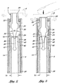
- FIG. 2 of the drawings shows the collet 4 at rest when no pushing force is applied to the actuator 9 via the push-button 8 of the dental handpiece 1 of FIG. 1.
- Actuator 9 has a relatively narrow force receiving end 20 that communicates with push-button 8 so that actuator 9 is adapted to slide in reciprocal directions through the spindle 14 relative to the collet 4 depending upon whether push-button 8 has been depressed by a dental worker.
- a first retaining ring 22 surrounds the force receiving end 20 of actuator 9 at one end of the hollow cylindrical spindle 14 to prevent the actuator from being pulled out of the spindle.
- a second retaining ring 24 is disposed within spindle 14 and spaced axially from the first retaining ring 22.
- Each of the retaining rings 22 and 24 is staked in place within the spindle 14.
- the spindle 14 may be manufactured with retaining ring 24 as an integral part thereof.
- Another stake 26 fixes the position of the collet 4 within spindle 14 so that the collet cannot be displaced relative to the spindle.
- a closed end, coiled compression spring 30 that is typically manufactured from spring steel is located within the cylindrical spindle 14 to control the axial (i.e. reciprocal) movement of actuator 9 through spindle 14 in a manner that will be described when referring to FIG. 3.
- Compression spring 30 surrounds a pair of wedge shaped tips 32 that project from the actuator 9 (best shown in FIG. 4).
- Compression spring 30 extends between the second retaining ring 24 within spindle 14 and a spring retaining notch 34 that is formed in the actuator 9.
- each of the wedge shaped tips 32 of actuator 9 form an angle that lies in a range of angles between 18 to 24 degrees, as opposed to a 30 degree angle that has heretofor been characteristic of some conventional actuators.
- the wedge shaped tips 32 form an angle of 22 degrees, as illustrated
- the compression spring 30 In the at-rest condition of the actuator 9 (with no pushing force applied to the force receiving end 20 thereof), the compression spring 30 will be in a relaxed, expanded condition as shown in FIG. 2.
- the compression spring 30 maintains the actuator 9 in spaced axial alignment with the collet 4 at the interior of cylindrical spindle 14, such that the pair of wedge shaped tips 32 of the actuator are received at the entrance to a respective pair of slots 36 that run axially through actuator 9 from the proximal end thereof. It is important to note that the wedge shaped tips 32 of actuator 9 are wider than the slots 36 of collet 4 at which tips 32 are received.
- the axially running slots 36 establish a pair of opposing, semi-cylindrical clamping fingers 38 at the proximal end of the collet 4 (also best shown in FIG. 4).
- the clamping fingers 38 are characterized by a spring-like memory and the ability to flex or rotate under stress.
- the clamping fingers 38 have a reduced diameter area 40, the inside diameter of which (designated D2 in FIG. 2) is less than the inside diameter (designated D1) of the cylindrical spindle 14. That is to say, by virtue of the reduced diameter area 40 of the flexible fingers 36 of collet 4, the dental bur (designated 50 in FIG. 1) is reliably clamped within the collet.
- a stroke gap 42 of approximately 0.004 inches is formed between the clamping fingers 38 and the cylindrical spindle 14 that surrounds the collet 4 and actuator 9.
- an axial pushing force is applied to the force receiving end 20 of the actuator 9 when a dental worker depresses the push-button 8 of the handpiece 1
- This axial pushing force at force receiving end 20 causes the actuator 9 to slide through the cylindrical spindle 14 in a direction towards the collet 4.
- the compression spring 30 is correspondingly compressed between the spring retaining notch 34 of actuator 9 and the retaining ring 24, the position of which is fixed within the spindle 14. At this point, compression spring 30 stores potential energy.
- the pair of wedge shaped tips 32 of actuator 9 are pushed into the pair of axial slots 36 of the collet 4.
- the wedge shaped tips 32 form a relatively small angle (of preferably 22 degrees) This angle and the fact that the wedge shaped tips 32 are wider than the width of axial slots 36 cause the flexible clamping fingers 38 at the proximal end of collet 4 to rotate outwardly and away from one another towards spindle 14 as the tips 32 are forced through respective slots 36 so as to cause collet 4 to release its grip on the dental bur.
- the improved angle of the wedge shaped tips 32 of actuator 9 sufficiently stresses the flexible fingers 38 of collet 4 so that fingers 38 rotate completely through the stroke gap 42 to strike spindle 14 while minimizing the axial pushing force necessary to move the wedge shaped tips 32 through slots 36.
- the dental worker can now simply remove (and replace) the existing dental bur from the distal end of the collet 4, inasmuch as the bur is no longer clamped at the reduced diameter area 40 of the flexible fingers 38.
- striking the spindle 14 limits the rotation of the flexible fingers 38 so as to avoid a deformation of the collet 4 and a possible loss of the spring-like memory in fingers 38.
- FIG. 4 of the drawings shows the spaced axial alignment of the actuator 9 with the collet 4 of the dental handpiece 1 of FIG. 1.
- FIG. 4 also shows the wedge shaped tips 32 projecting from the actuator 9 and adapted to be moved towards and into receipt by the respective axially running slots 36 that separate the flexible clamping fingers 38 at the proximal end of collet 4 when an axial pushing force is applied to the force receiving end 20 of actuator 9 in the manner that was previously disclosed when referring to FIG. 3 so that a dental bur can be removed from (or inserted within) the distal end of the collet.
Landscapes
- Health & Medical Sciences (AREA)
- Oral & Maxillofacial Surgery (AREA)
- Dentistry (AREA)
- Epidemiology (AREA)
- Life Sciences & Earth Sciences (AREA)
- Animal Behavior & Ethology (AREA)
- General Health & Medical Sciences (AREA)
- Public Health (AREA)
- Veterinary Medicine (AREA)
- Dental Tools And Instruments Or Auxiliary Dental Instruments (AREA)
Claims (10)
- Ein Dentalhandstück (1) zum Halten eines Werkstücks (50), das verwendet wird, um die Zähne eines Patienten zu behandeln, wobei das Dentalhandstück Folgendes aufweist:eine hohle Spann- bzw. Klemmhülse (4) mit einem proximalen und distalen Ende, wobei das Werkstück (50) durch das distale Ende auswechselbar bzw. herausnehmbar aufgenommen wird, und zwar so, dass es von der Klemmhülse umgeben und an deren proximalen Ende eingespannt wird;einen Klemmhülsenbetätiger (9), der in einer beabstandeten axialen Ausrichtung mit der Klemmhülse (4) angeordnet ist, wobei der Klemmhülsenbetätiger Werkstückfreigabemittel (32) besitzt, die so bemessen sind, dass sie nach innen durch das proximale Ende der Klemmhülse aufgenommen werden;eine zylindrische Spindel (14), die sowohl die axial ausgerichtete Klemmhülse (4) als auch den Klemmhülsenbetätiger (9) umgibt, wobei die Klemmhülse fest an der Spindel angebracht ist und der Klemmhülsenbetätiger durch die Spindel relativ zu der Klemmhülse hin- und hergleitbar ist;einen Druckknopf (8) an den eine axiale Druckkraft angelegt wird, wobei die axiale Druckkraft von dem Druckknopf auf den Klemmhülsenbetätiger (9) übertragen wird, um zu bewirken, dass dieser durch die Spindel (14) zu der Klemmhülse (4) hin gleitet, so dass die Werkstückfreigabemittel (32) des Klemmhülsenbetätigers in das proximale Ende der Klemmhülse gedrückt werden, um das proximale Ende zu zwingen, sich nach außen und in den Kontakt mit der Spindel zu bewegen, wodurch das Werkstück aus der Klemmhülse freigegeben wird; unddadurch gekennzeichnet, dassFedermittel (30) für den Eingriff mit dem Klemmhülsenbetätiger (9) ausgerichtet sind, wobei die Federmittel durch den Klemmhülsenbetätiger komprimiert werden, wenn dieser durch die Spindel (14) gedrückt und zu der Klemmhülse (4) hin bewegt wird, und zwar ansprechend auf die axiale Druckkraft, die an den Druckknopf (8) angelegt wird, und wobei sich die Federmittel ausdehnen, um den Klemmhülsenbetätiger zu veranlassen durch die Spindel und weg von der Klemmhülse zu gleiten, wenn die axiale Druckkraft beendet wird.
- Dentalhandstück (1) gemäß Anspruch 1, wobei sowohl das proximale als auch das distale Ende der hohlen Klemmhülse (4) einen Innendurchmesser besitzen, wobei der Innendurchmesser des proximalen Endes, an das das Werkstück (50) geklemmt bzw. gespannt ist, kleiner ist als der Innendurchmesser des distalen Endes.
- Dentalhandstück (1) gemäß Anspruch 1, wobei das proximale Ende der hohlen Klemmhülse (4), an das das Werkstück (50) geklemmt ist, aus einer Vielzahl elastischer Finger (38) mit automatischer Rückkehr in eine Ausgangsposition (spring memory) besteht, wobei die elastischen Finger ausgelegt sind, um sich derart nach außen und weg voneinander zu drehen, dass sie sich in den Kontakt mit der Spindel (14) bewegen, und zwar ansprechend darauf, dass die Werkstückfreigabemittel (32) des Klemmhülsenbetätigers (9) in das proximale Ende der Klemmhülse gedrückt werden.
- Dentalhandstück (1) gemäß Anspruch 3, wobei die Werkstückfreigabemittel (32) des Klemmhülsenbetätigers (9) eine Vielzahl keilförmiger Spitzen (32) umfasst, die in das proximale Ende der hohlen Klemmhülse (4) gedrückt werden, um die Entsprechenden der Vielzahl elastischer Finger (38) der Klemmhülse zu zwingen, sich nach außen und weg voneinander zu drehen, um sich so in den Kontakt mit der Spindel (14) zu bewegen, um das Werkstück (50) aus der Klemmhülse freizugeben.
- Dentalhandstück (1) gemäß Anspruch 4, wobei jede der Vielzahl keilförmiger Spitzen (32) des Klemmhülsenbetätigers (9) einen Winkel von ungefähr 22 Grad bildet.
- Dentalhandstück (1) gemäß Anspruch 4, wobei sowohl das proximale als auch das distale Ende der Klemmhülse (4) einen Außendurchmesser besitzt, wobei der Außendurchmesser des proximalen Endes kleiner ist als der Außendurchmesser des distalen Endes, so dass ein Hubspalt (stroke gap) (42) zwischen dem proximalen Ende und der Spindel (14) entsteht, wobei sich die Vielzahl elastischer Finger (38) an dem proximalen Ende der Klemmhülse durch den Hubspalt dreht, um sich in den Kontakt mit der Spindel zu bewegen, wenn die Vielzahl keilförmiger Spitzen des Klemmhülsenbetätigers in das proximale Ende der Klemmhülse gedrückt wird.
- Dentalhandstück (1) gemäß Anspruch 1, wobei die Federmittel eine Spiraldruckfeder (30) sind, die zumindest einen Teil des Klemmhülsenbetätigers (9) umgibt, wobei dieser einen darin ausgebildeten Einschnitt bzw. Ausnehmung (34) besitzt, an der er mit der Spiraldruckfeder in Eingriff steht.
- Dentalhandstück (1) gemäß Anspruch 1, wobei die Klemmhülse (4) zylindrisch ist und ihr proximales Ende eine Vielzahl elastischer Finger (38) besitzt, die durch eine entsprechende Vielzahl axialer Schlitze (36) voneinander getrennt sind, und die ausgelegt sind, sich ansprechend auf eine Druckkraft nach außen zu drehen; und
wobei der Klemmhülsenbetätiger (9) eine Vielzahl nach außen wegragender Werkstückfreigabespitzen (32) mit einer Winkelform von ungefähr 22 Grad umfasst und axial mit der Vielzahl axialer Schlitze (36) ausgerichtet ist, die die Vielzahl elastischer Finger (38) an dem proximalen Ende der Klemmhülse trennt; und
wobei die axiale Druckkraft von dem Druckknopf auf den Klemmhülsenbetätiger (9) übertragen wird, um zu bewirken, dass der Klemmhülsenbetätiger durch die Spindel (14) und zu der Klemmhülse (4) hin gleitet, um die Vielzahl von Werkstückfreigabespitzen (32) des Klemmhülsenbetätigers in entsprechende Schlitze der Vielzahl axialer Schlitze (36) am proximalen Ende der Klemmhülse zu drücken, um zu bewirken, dass die Vielzahl flexibler Finger (38) sich nach außen zur Spindel hin drehen, wodurch das Werkstück von dem proximalen Ende der klemmhülse freigegeben wird. - Dentalhandstück gemäß Anspruch 8, das ferner Federmittel (30) umfasst, welche mit dem Klemmhülsenbetätiger (9) in Eingriff stehen, wobei die Federmittel zusammengedrückt bzw. komprimiert werden, wenn der Klemmhülstenbetätiger durch die Spindel (14) und zu der Klemmhülse (4) hin gedrückt wird, und zwar ansprechend darauf, dass die axiale Druckkraft auf den Druckknopf (8) angewandt wird, und wobei die Federmittel sich ausdehnen, um zu bewirken, dass der Klemmhülsenbetätiger durch die Spindel und weg von der Klemmhülse gleitet, wenn die axiale Druckkraft beendet wird.
- Dentalhandstück gemäß Anspruch 9, wobei die Federmittel (30) eine Schraubenkompressionsfeder ist, die zumindest einen Teil des Klemmhülsenbetätigers (9) umgibt, wobei der Klemmhülsenbetätiger eine Kerbe oder Nut (34) darin ausgebildet besitzt, an der die Schraubenkompressionsfeder an- bzw. eingreift.
Priority Applications (3)
| Application Number | Priority Date | Filing Date | Title |
|---|---|---|---|
| DE60119484T DE60119484T2 (de) | 2001-02-16 | 2001-02-16 | Zahnärztliches Handstück mit verbesserter Spannvorrichtung |
| AT01103883T ATE325582T1 (de) | 2001-02-16 | 2001-02-16 | Zahnärztliches handstück mit verbesserter spannvorrichtung |
| EP01103883A EP1232731B1 (de) | 2001-02-16 | 2001-02-16 | Zahnärztliches Handstück mit verbesserter Spannvorrichtung |
Applications Claiming Priority (1)
| Application Number | Priority Date | Filing Date | Title |
|---|---|---|---|
| EP01103883A EP1232731B1 (de) | 2001-02-16 | 2001-02-16 | Zahnärztliches Handstück mit verbesserter Spannvorrichtung |
Publications (2)
| Publication Number | Publication Date |
|---|---|
| EP1232731A1 EP1232731A1 (de) | 2002-08-21 |
| EP1232731B1 true EP1232731B1 (de) | 2006-05-10 |
Family
ID=8176523
Family Applications (1)
| Application Number | Title | Priority Date | Filing Date |
|---|---|---|---|
| EP01103883A Expired - Lifetime EP1232731B1 (de) | 2001-02-16 | 2001-02-16 | Zahnärztliches Handstück mit verbesserter Spannvorrichtung |
Country Status (3)
| Country | Link |
|---|---|
| EP (1) | EP1232731B1 (de) |
| AT (1) | ATE325582T1 (de) |
| DE (1) | DE60119484T2 (de) |
Cited By (1)
| Publication number | Priority date | Publication date | Assignee | Title |
|---|---|---|---|---|
| DE102010037791A1 (de) | 2010-09-27 | 2012-03-29 | Minebea Co., Ltd. | Spanneinrichtung für ein Dentalwerkzeug in einem Dentalturbinenhandstück |
Families Citing this family (1)
| Publication number | Priority date | Publication date | Assignee | Title |
|---|---|---|---|---|
| DE102005001368B8 (de) * | 2005-01-11 | 2007-01-25 | Lpkf Laser & Elektronika D.O.O. | Werkzeugaufnahme |
Family Cites Families (5)
| Publication number | Priority date | Publication date | Assignee | Title |
|---|---|---|---|---|
| DE3402635C2 (de) * | 1984-01-26 | 1986-11-13 | Kaltenbach & Voigt Gmbh & Co, 7950 Biberach | Spannvorrichtung zum Einspannen von Werkzeugen |
| DE3768794D1 (de) * | 1986-12-22 | 1991-04-25 | Siemens Ag | Spannvorrichtung fuer insbesondere zahnaerztliche werkzeuge. |
| EP0421907A1 (de) * | 1989-09-07 | 1991-04-10 | Micro Mega S.A. | Gerät zur LÀ¶sung bzw. Festsetzung der Kupplung eines zahnärztlichen Handstückes |
| US6190168B1 (en) * | 1999-02-17 | 2001-02-20 | Stanley A. Bowen | Dental handpiece having improved bur release means |
| US6155826A (en) * | 1999-10-25 | 2000-12-05 | Howard; James | Grip chuck spindle assembly for a dental handpiece |
-
2001
- 2001-02-16 DE DE60119484T patent/DE60119484T2/de not_active Expired - Fee Related
- 2001-02-16 EP EP01103883A patent/EP1232731B1/de not_active Expired - Lifetime
- 2001-02-16 AT AT01103883T patent/ATE325582T1/de not_active IP Right Cessation
Cited By (2)
| Publication number | Priority date | Publication date | Assignee | Title |
|---|---|---|---|---|
| DE102010037791A1 (de) | 2010-09-27 | 2012-03-29 | Minebea Co., Ltd. | Spanneinrichtung für ein Dentalwerkzeug in einem Dentalturbinenhandstück |
| DE102010037791B4 (de) | 2010-09-27 | 2024-05-08 | Minebea Mitsumi Inc. | Spanneinrichtung für ein Dentalwerkzeug in einem Dentalturbinenhandstück |
Also Published As
| Publication number | Publication date |
|---|---|
| EP1232731A1 (de) | 2002-08-21 |
| DE60119484D1 (de) | 2006-06-14 |
| DE60119484T2 (de) | 2007-04-19 |
| ATE325582T1 (de) | 2006-06-15 |
Similar Documents
| Publication | Publication Date | Title |
|---|---|---|
| US6190168B1 (en) | Dental handpiece having improved bur release means | |
| USRE37358E1 (en) | Tool holding mechanism for a motor driven surgical instrument | |
| US5839196A (en) | Wrenchless collet for surgical blade | |
| US3835858A (en) | Surgical air drill | |
| EP2502583B1 (de) | Operationsinstrument mit rotierendem Schneideelement und Schnellentkupplungsanordnung | |
| US4157714A (en) | Wire inserter and sterile wire pack | |
| US7066940B2 (en) | Surgical instrument with rotary cutting member and quick release coupling arrangement | |
| US5112338A (en) | Surgical instrument for removing artificial acetabular cups | |
| JP4928574B2 (ja) | 外科用ハンドピース | |
| JP6338653B2 (ja) | 動的係止装置 | |
| US20040122460A1 (en) | Surgical instrument with telescoping attachment | |
| US5354075A (en) | Keyless drill chuck | |
| US5257995A (en) | Apparatus for removing a prosthesis from a bone | |
| US4903784A (en) | Impact hammer power tool | |
| US5203417A (en) | Handheld impact power tool | |
| US4811736A (en) | Surgical drill and bur for use therewith | |
| EP2736442B1 (de) | Zahnärztliches handstück mit einem positivantriebsfutter und einer bohranordnung | |
| JP2001138258A (ja) | 電動ドライバのビス捕獲装置 | |
| US20050173141A1 (en) | Power tool with detachable drive end | |
| JP2005502487A (ja) | 中子付きらせんコイル状挿入部用の抜取り工具 | |
| US6918913B2 (en) | Tool bit drive shaft connection and method | |
| EP1232731A1 (de) | Zahnärztliches Handstück mit verbesserter Spannvorrichtung | |
| US6821120B2 (en) | Dental handpiece with tool holder | |
| US6155826A (en) | Grip chuck spindle assembly for a dental handpiece | |
| JP2005532085A (ja) | コーティングされた歯科用ハンドピース |
Legal Events
| Date | Code | Title | Description |
|---|---|---|---|
| PUAI | Public reference made under article 153(3) epc to a published international application that has entered the european phase |
Free format text: ORIGINAL CODE: 0009012 |
|
| AK | Designated contracting states |
Kind code of ref document: A1 Designated state(s): AT BE CH CY DE DK ES FI FR GB GR IE IT LI LU MC NL PT SE TR |
|
| AX | Request for extension of the european patent |
Free format text: AL;LT;LV;MK;RO;SI |
|
| 17P | Request for examination filed |
Effective date: 20030220 |
|
| AKX | Designation fees paid |
Designated state(s): AT BE CH CY DE DK ES FI FR GB GR IE IT LI LU MC NL PT SE TR |
|
| 17Q | First examination report despatched |
Effective date: 20040729 |
|
| GRAP | Despatch of communication of intention to grant a patent |
Free format text: ORIGINAL CODE: EPIDOSNIGR1 |
|
| GRAS | Grant fee paid |
Free format text: ORIGINAL CODE: EPIDOSNIGR3 |
|
| GRAA | (expected) grant |
Free format text: ORIGINAL CODE: 0009210 |
|
| AK | Designated contracting states |
Kind code of ref document: B1 Designated state(s): AT BE CH CY DE DK ES FI FR GB GR IE IT LI LU MC NL PT SE TR |
|
| PG25 | Lapsed in a contracting state [announced via postgrant information from national office to epo] |
Ref country code: IT Free format text: LAPSE BECAUSE OF FAILURE TO SUBMIT A TRANSLATION OF THE DESCRIPTION OR TO PAY THE FEE WITHIN THE PRESCRIBED TIME-LIMIT;WARNING: LAPSES OF ITALIAN PATENTS WITH EFFECTIVE DATE BEFORE 2007 MAY HAVE OCCURRED AT ANY TIME BEFORE 2007. THE CORRECT EFFECTIVE DATE MAY BE DIFFERENT FROM THE ONE RECORDED. Effective date: 20060510 Ref country code: AT Free format text: LAPSE BECAUSE OF FAILURE TO SUBMIT A TRANSLATION OF THE DESCRIPTION OR TO PAY THE FEE WITHIN THE PRESCRIBED TIME-LIMIT Effective date: 20060510 Ref country code: BE Free format text: LAPSE BECAUSE OF FAILURE TO SUBMIT A TRANSLATION OF THE DESCRIPTION OR TO PAY THE FEE WITHIN THE PRESCRIBED TIME-LIMIT Effective date: 20060510 Ref country code: LI Free format text: LAPSE BECAUSE OF FAILURE TO SUBMIT A TRANSLATION OF THE DESCRIPTION OR TO PAY THE FEE WITHIN THE PRESCRIBED TIME-LIMIT Effective date: 20060510 Ref country code: FI Free format text: LAPSE BECAUSE OF FAILURE TO SUBMIT A TRANSLATION OF THE DESCRIPTION OR TO PAY THE FEE WITHIN THE PRESCRIBED TIME-LIMIT Effective date: 20060510 Ref country code: CH Free format text: LAPSE BECAUSE OF FAILURE TO SUBMIT A TRANSLATION OF THE DESCRIPTION OR TO PAY THE FEE WITHIN THE PRESCRIBED TIME-LIMIT Effective date: 20060510 Ref country code: NL Free format text: LAPSE BECAUSE OF FAILURE TO SUBMIT A TRANSLATION OF THE DESCRIPTION OR TO PAY THE FEE WITHIN THE PRESCRIBED TIME-LIMIT Effective date: 20060510 |
|
| REG | Reference to a national code |
Ref country code: GB Ref legal event code: FG4D |
|
| REG | Reference to a national code |
Ref country code: CH Ref legal event code: EP |
|
| REF | Corresponds to: |
Ref document number: 60119484 Country of ref document: DE Date of ref document: 20060614 Kind code of ref document: P |
|
| REG | Reference to a national code |
Ref country code: IE Ref legal event code: FG4D |
|
| PG25 | Lapsed in a contracting state [announced via postgrant information from national office to epo] |
Ref country code: DK Free format text: LAPSE BECAUSE OF FAILURE TO SUBMIT A TRANSLATION OF THE DESCRIPTION OR TO PAY THE FEE WITHIN THE PRESCRIBED TIME-LIMIT Effective date: 20060810 Ref country code: SE Free format text: LAPSE BECAUSE OF FAILURE TO SUBMIT A TRANSLATION OF THE DESCRIPTION OR TO PAY THE FEE WITHIN THE PRESCRIBED TIME-LIMIT Effective date: 20060810 |
|
| PG25 | Lapsed in a contracting state [announced via postgrant information from national office to epo] |
Ref country code: ES Free format text: LAPSE BECAUSE OF FAILURE TO SUBMIT A TRANSLATION OF THE DESCRIPTION OR TO PAY THE FEE WITHIN THE PRESCRIBED TIME-LIMIT Effective date: 20060821 |
|
| PG25 | Lapsed in a contracting state [announced via postgrant information from national office to epo] |
Ref country code: PT Free format text: LAPSE BECAUSE OF FAILURE TO SUBMIT A TRANSLATION OF THE DESCRIPTION OR TO PAY THE FEE WITHIN THE PRESCRIBED TIME-LIMIT Effective date: 20061010 |
|
| NLV1 | Nl: lapsed or annulled due to failure to fulfill the requirements of art. 29p and 29m of the patents act | ||
| REG | Reference to a national code |
Ref country code: CH Ref legal event code: PL |
|
| PG25 | Lapsed in a contracting state [announced via postgrant information from national office to epo] |
Ref country code: MC Free format text: LAPSE BECAUSE OF NON-PAYMENT OF DUE FEES Effective date: 20070228 |
|
| PLBE | No opposition filed within time limit |
Free format text: ORIGINAL CODE: 0009261 |
|
| STAA | Information on the status of an ep patent application or granted ep patent |
Free format text: STATUS: NO OPPOSITION FILED WITHIN TIME LIMIT |
|
| 26N | No opposition filed |
Effective date: 20070213 |
|
| EN | Fr: translation not filed | ||
| PG25 | Lapsed in a contracting state [announced via postgrant information from national office to epo] |
Ref country code: IE Free format text: LAPSE BECAUSE OF NON-PAYMENT OF DUE FEES Effective date: 20070216 |
|
| PG25 | Lapsed in a contracting state [announced via postgrant information from national office to epo] |
Ref country code: GR Free format text: LAPSE BECAUSE OF FAILURE TO SUBMIT A TRANSLATION OF THE DESCRIPTION OR TO PAY THE FEE WITHIN THE PRESCRIBED TIME-LIMIT Effective date: 20060811 Ref country code: FR Free format text: LAPSE BECAUSE OF FAILURE TO SUBMIT A TRANSLATION OF THE DESCRIPTION OR TO PAY THE FEE WITHIN THE PRESCRIBED TIME-LIMIT Effective date: 20070309 |
|
| PGFP | Annual fee paid to national office [announced via postgrant information from national office to epo] |
Ref country code: DE Payment date: 20080227 Year of fee payment: 8 Ref country code: GB Payment date: 20080220 Year of fee payment: 8 |
|
| PG25 | Lapsed in a contracting state [announced via postgrant information from national office to epo] |
Ref country code: FR Free format text: LAPSE BECAUSE OF FAILURE TO SUBMIT A TRANSLATION OF THE DESCRIPTION OR TO PAY THE FEE WITHIN THE PRESCRIBED TIME-LIMIT Effective date: 20060510 |
|
| PG25 | Lapsed in a contracting state [announced via postgrant information from national office to epo] |
Ref country code: CY Free format text: LAPSE BECAUSE OF FAILURE TO SUBMIT A TRANSLATION OF THE DESCRIPTION OR TO PAY THE FEE WITHIN THE PRESCRIBED TIME-LIMIT Effective date: 20060510 Ref country code: LU Free format text: LAPSE BECAUSE OF NON-PAYMENT OF DUE FEES Effective date: 20070216 |
|
| PG25 | Lapsed in a contracting state [announced via postgrant information from national office to epo] |
Ref country code: TR Free format text: LAPSE BECAUSE OF FAILURE TO SUBMIT A TRANSLATION OF THE DESCRIPTION OR TO PAY THE FEE WITHIN THE PRESCRIBED TIME-LIMIT Effective date: 20060510 |
|
| GBPC | Gb: european patent ceased through non-payment of renewal fee |
Effective date: 20090216 |
|
| PG25 | Lapsed in a contracting state [announced via postgrant information from national office to epo] |
Ref country code: DE Free format text: LAPSE BECAUSE OF NON-PAYMENT OF DUE FEES Effective date: 20090901 |
|
| PG25 | Lapsed in a contracting state [announced via postgrant information from national office to epo] |
Ref country code: GB Free format text: LAPSE BECAUSE OF NON-PAYMENT OF DUE FEES Effective date: 20090216 |