EP1232794A1 - Verfahren zum Trennen eines Mehrphasengemisches und Dekantierzentrifungensystem zur Durchführung des Verfahrens - Google Patents
Verfahren zum Trennen eines Mehrphasengemisches und Dekantierzentrifungensystem zur Durchführung des Verfahrens Download PDFInfo
- Publication number
- EP1232794A1 EP1232794A1 EP01102962A EP01102962A EP1232794A1 EP 1232794 A1 EP1232794 A1 EP 1232794A1 EP 01102962 A EP01102962 A EP 01102962A EP 01102962 A EP01102962 A EP 01102962A EP 1232794 A1 EP1232794 A1 EP 1232794A1
- Authority
- EP
- European Patent Office
- Prior art keywords
- weir
- pond depth
- centrifuge
- liquid
- speed
- Prior art date
- Legal status (The legal status is an assumption and is not a legal conclusion. Google has not performed a legal analysis and makes no representation as to the accuracy of the status listed.)
- Granted
Links
Images




Classifications
-
- B—PERFORMING OPERATIONS; TRANSPORTING
- B04—CENTRIFUGAL APPARATUS OR MACHINES FOR CARRYING-OUT PHYSICAL OR CHEMICAL PROCESSES
- B04B—CENTRIFUGES
- B04B1/00—Centrifuges with rotary bowls provided with solid jackets for separating predominantly liquid mixtures with or without solid particles
- B04B1/20—Centrifuges with rotary bowls provided with solid jackets for separating predominantly liquid mixtures with or without solid particles discharging solid particles from the bowl by a conveying screw coaxial with the bowl axis and rotating relatively to the bowl
- B04B1/2016—Driving control or mechanisms; Arrangement of transmission gearing
-
- B—PERFORMING OPERATIONS; TRANSPORTING
- B04—CENTRIFUGAL APPARATUS OR MACHINES FOR CARRYING-OUT PHYSICAL OR CHEMICAL PROCESSES
- B04B—CENTRIFUGES
- B04B1/00—Centrifuges with rotary bowls provided with solid jackets for separating predominantly liquid mixtures with or without solid particles
- B04B1/20—Centrifuges with rotary bowls provided with solid jackets for separating predominantly liquid mixtures with or without solid particles discharging solid particles from the bowl by a conveying screw coaxial with the bowl axis and rotating relatively to the bowl
-
- B—PERFORMING OPERATIONS; TRANSPORTING
- B04—CENTRIFUGAL APPARATUS OR MACHINES FOR CARRYING-OUT PHYSICAL OR CHEMICAL PROCESSES
- B04B—CENTRIFUGES
- B04B1/00—Centrifuges with rotary bowls provided with solid jackets for separating predominantly liquid mixtures with or without solid particles
- B04B1/20—Centrifuges with rotary bowls provided with solid jackets for separating predominantly liquid mixtures with or without solid particles discharging solid particles from the bowl by a conveying screw coaxial with the bowl axis and rotating relatively to the bowl
- B04B2001/2041—Centrifuges with rotary bowls provided with solid jackets for separating predominantly liquid mixtures with or without solid particles discharging solid particles from the bowl by a conveying screw coaxial with the bowl axis and rotating relatively to the bowl with baffles, plates, vanes or discs attached to the conveying screw
-
- B—PERFORMING OPERATIONS; TRANSPORTING
- B04—CENTRIFUGAL APPARATUS OR MACHINES FOR CARRYING-OUT PHYSICAL OR CHEMICAL PROCESSES
- B04B—CENTRIFUGES
- B04B1/00—Centrifuges with rotary bowls provided with solid jackets for separating predominantly liquid mixtures with or without solid particles
- B04B1/20—Centrifuges with rotary bowls provided with solid jackets for separating predominantly liquid mixtures with or without solid particles discharging solid particles from the bowl by a conveying screw coaxial with the bowl axis and rotating relatively to the bowl
- B04B2001/2083—Configuration of liquid outlets
Definitions
- the pond depth is defined as the difference between external and inner diameter of the rotating in the centrifuge drum Liquid ring.
- a decanter centrifuge with at least partial hydraulic Promote how you perform the procedure is assumed is known from DE 43 20 265 C2.
- a liquid ring is placed in the rotating centrifuge drum between the submersible and the liquid weir certain fill level, the so-called pond depth and thus a hydrostatic due to the liquid phase Generates pressure that contributes to the discharge of the dry phase.
- the hydraulic delivery can be in addition to or instead of the discharge with a rotatable with differential speed Snail done.
- the weir is essentially in two parts.
- a Weir plate closes the cylindrical shell of the centrifuge drum and rotates with it. At least she is a passage for draining a liquid the centrifuge drum.
- the weir plate is a parallel one Throttle disc associated with the axially displaceable the stationary storage of the rotatable centrifuge drum is arranged. Between the rotating weir plate and the stationary throttle disc forms a gap that extends in the radial direction and through which the liquid phase flung out of the centrifuge drum becomes.
- the axial displacement of the throttle disc can Weir gap width can be varied. By reducing the The width of the weir gap becomes a pressure increase in the liquid phase causes that this increases the dry phase pushes out of the centrifuge drum. The liquid phase partially penetrates into the dry phase and reduces its concentration of dry matter. Vice versa an expansion of the weir gap causes a reduction in pressure, reduced hydraulic delivery and finally an increase in dry matter concentration in the dry phase.
- This liquid weir has for a decanter centrifuge has proven itself as it is with a rotating centrifuge drum is adjustable and so a regulation of the dry matter concentration allowed over the weir gap.
- a regulation of the weir gap width can be based on concentration and Amount changes in the supplied multi-phase mixture in ongoing process.
- a pneumatic liquid weir is known from DE 195 00 600, by blowing compressed gas into the weir gap the flow resistance of the liquid phase in the weir is increased, which increases the pond depth. Also with this training of the liquid weir is a regulation the dry matter concentration through a weir adjustment possible during operation.
- a decanter with to operate a plunger and a liquid weir is that in a base load operation with largely constant Amount and concentration of the feed an optimization can be made in terms of energy consumption and that at the same time a willingness to react to sudden Changes in the inflow is given by the fact that the weir in returned a middle position defined by the tolerance range from which it becomes both the dry phase thicken more than it can further dilute.
- a decanter centrifuge is used, the liquid weir of which consists of a weir plate with at least one liquid recess and a throttle plate, which is mounted in a stationary manner with a weir gap opposite the weir plate and is axially displaceable.
- the pond depth x T must be reduced by increasing the weir gap width x W and increasing by reducing the weir gap width x W.
- a corresponding weir gap width tolerance range with a lower weir gap width x W, U and an upper weir gap width x W, O is assigned to the pond depth tolerance range.
- a decanter centrifuge system with the features of the preamble of claim 17 is from the publication "Intelligent measurement and control technology for optimized process control in wastewater treatment” (DR. H.-J. BEYER / M. FLEUTER, Westfalia Separator Industry GmbH in: 4. Mersebuger Conference automation, measuring methods and experiments in mechanical process engineering, November 1999).
- the pond depth x T is adjusted depending on the dry matter concentration c TS . This enables extensive automation of the phase separation process.
- operator intervention is still required if there are major changes in the type, quantity and / or concentration of the incoming product and the weir has reached a limit position from which it can no longer react to the changes that have occurred.
- high energy consumption can be determined in the ongoing process due to the high drum speeds.
- a decanter centrifuge system of the type mentioned above, which is characterized by a speed control device for controlling the drum speed n Z as a function of the pond depth x T and the dry matter concentration c TS , with a concentration signal input (221), a pond depth signal input (222) and a speed control signal output (224).
- the weir control system can also the dry matter concentration by changing the drum speed regulated or at least reduced to the extent that the dry matter remains flowable and clogging the discharge lines is prevented.
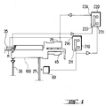
- a sensor device 60 is arranged on the dry substance discharge line 27, with which a dry substance concentration c TS can be measured in the dry phase drawn off there.
- the measurement signal from the sensor device 60 is applied to the concentration signal input 211 of a weir control device 210.
- a weir gap width control signal with which the weir adjustment device 35 is acted on, is output at its control output 214.
- the design of the weir control device 210 as a PI controller has proven to be particularly suitable. Due to a high integrating component, control deviations can initially be averaged over a period of time, so that the decanting centrifuge system does not swing up.
- the outer The circumference of the exchange disk 14 is spaced from the inner circumference of the centrifuge jacket 21, so that there is a passage of liquid or dry substance is possible.
- At the The end of the conical area includes the drum jacket 21 provided at least one dry matter discharge recess 22.
- a liquid weir 30 is arranged at the opposite axial end of the centrifuge drum 20 at the opposite axial end of the centrifuge drum 20 .
- the centrifuge drum 20 is completed with a weir plate 32, which has individual recesses, the leakage of liquid allow.
- the weir plate 32 is opposite Throttle plate 34 arranged on a stationary part the housing of the decanter centrifuge 1 is attached and does not rotate with the cylinder drum 20.
- the throttle plate 34 is displaceable parallel to the axis of rotation of the cylinder drum 20.
- the width of one between weir plate 32 and Throttle plate 34 forming weir gap 33 is thus also variable with rotating cylinder drum 20.
- the adjustment of the throttle plate 34 can be via electrical or pneumatic adjustment devices that are made via a gap width signal are controllable, which from the control output 214 of a weir control device 210 is output.
- the product to be processed is a Multi-phase mixture containing at least one liquid phase and has an insoluble solid phase.
- the solid phase with the lowest possible Separate residual liquid nevertheless the dry phase consisting of solid and residual liquid still be conveyable through pipelines, so that it must remain fluid. This objective arises for example in the processing of sewage sludge in municipal Sewage treatment plants.
- the weir gap width x W of the weir gap 33 is initially set to a starting value when the process is started, which is approximately 0.5% to 5% of the maximum adjustable weir gap width x W, max .
- the pressure in the annular space 26 rises through the narrow weir gap 33, so that liquid 54 presses into the centrifuged drying phase 52.
- the dry phase 52 thus diluted again is conveyed past the immersion disk 14 to the dry substance discharge recess 22.
- the width ratios on the weir are shown schematically in FIGS. 5a and 5b.
- the liquid phase 54 is flung radially outwards due to the high centrifugal forces.
- the gap width x W is then without influence on the hydraulic conveyance of the drying phase 52 in the centrifuge drum 20.
- the maximum adjustable weir gap width x W, max is thus the width of the weir gap 33 at which the throttle plate 34 is just still being wetted by the emerging liquid phase 54 takes place and thus a regulation of the dynamic pressure of the liquid phase can take place.
- the weir gap width x W is then regulated as a function of the dry matter concentration c TS in the subtracted drying phase 52 until a predetermined target dry matter concentration c TS, 0 is reached .
- the operating point can also be in the middle of the process effective travel range of the throttle plate 34 set so that there are equally large reserves for the Travel path of the throttle plate in both directions.
- the optimization of the method according to the invention begins with a view to saving energy, provided that the regulated weir gap width x W is not within the weir gap width tolerance range 37.
- the drum speed n Z is increased so that the dry matter concentration c TS tends to be increased in the dry phase. This is counteracted by an increase in pressure in the liquid phase, which is brought about by reducing the weir gap width x W.
- the throttle plate of the weir is again positioned in the weir gap width tolerance range 37.
- the weir gap width x W is readjusted as a function of the dry matter concentration c TS in the subtracted drying phase 52 until a predetermined desired dry matter concentration c TS, 0 is reached .
- the weir 30 is then in a position in which there are still sufficient reserves to move the throttle valve 34 in the process-technically effective range and thus to change the weir gap width x W if a change in the quantity and / or composition of the product added so requires ,
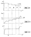
- FIG. 4 shows the time course of the drum speed n Z (FIG. 4a), the weir gap width x W (FIG. 4b) and the volume flow of the product supplied (FIG. 4c) in the method according to the invention.
- phase "IV” the weir gap width x W after the readjustment has been carried out is within the weir gap width tolerance range 37.
- phase "V" of FIG. 4c an increase in the inflow amount, for example due to a rain shower, is recorded. At the same time, the solids content is lower. In order to keep the dry matter concentration c TS of the discharge constant, the weir gap width x W is greatly increased out of the tolerance range 37 in order to be able to draw off more and more liquid.
- the weir control device 210 (cf. FIGS. 1, 2) is used for the weir position the discharge concentration to the desired Setpoint adjusted. During this time the function is the speed control device 220 is still bridged. After this this bridging period has ended, the scheme Approved. For the specific application is considered of machine-technical and plant-specific Data of the optimal working point of the weir control system 210 set. From this operating point the Area in which the decanter centrifuge is procedural and works optimally in terms of energy consumption. The center and width of this area become the definition of a weir gap width tolerance range.
- the current position of the weir is then determined and with compared to the weir gap tolerance range.
- the control valve's control value is below of this area, the decanter is underutilized and the drum speed, which is related to the energy consumption of the Separation process is directly related to one Speed level value can be reduced.
- the control output value leaves the range in positive Direction, the drum speed is too low and must be raised the weir position in the weir gap width tolerance range due.
Landscapes
- Centrifugal Separators (AREA)
- Cyclones (AREA)
Abstract
Description
- eine ringförmige Tauchscheibe, die an ihrem inneren Umfang mit einer Welle verbunden ist und deren Außendurchmesser kleiner ist als der Innendurchmesser einer Zentrifugentrommel; und
- wenigstens ein endseitig an der Zentrifugentrommel angeordnetes Flüssigkeitswehr mit einem Wehrspalt, durch den die Flüssigkeitsphase aus der Zentrifugentrommel ableitbar ist, und mit einer Teichtiefeneinstellvorrichtung, mit der die Teichtiefe xT der in der Zentrifugentrommel rotierenden Flüssigkeitsphase einstellbar ist,
- a) Anlaufen der Zentrifugentrommel auf eine Starttrommeldrehzahl nZ,1 und Einstellen der Teichtiefe xT auf eine Startteichtiefe xT,1 ;
- b) Einleiten des Mehrphasengemisches in die rotierende Zentrifugentrommel;
- c) Abzug der Trockenphase durch die wenigstens eine Trockensubstanzaustragsausnehmung und Abzug der Flüssigkeitsphase durch den Wehrspalt;
- d) Regeln der Teichtiefe XT mittels der Teichtiefeneinstellvorrichtung in Abhängigkeit von der Trockensubstanzkonzentration CTS in der abgezogenen Trockenphase bis zum Erreichen einer vorgegebenen Soll-Trockensubstanzkonzentration CTS,1.
Ein Verfahren, das zum Betreiben einer Dekantierzentrifuge mit einem verstellbaren Flüssigkeitswehr geeignet wäre, ist nicht offenbart.
- einer Dekantierzentrifuge umfassend:
- eine Hohlwelle, die wenigstens ein innenliegendes Einlaufrohr aufweist;
- eine um die Hohlwelle rotierbare Zentrifugentrommel, welche mit wenigstens einer in ihren Trommelmantel eingebrachten Trockensubstanzaustragsausnehmung versehen ist;
- eine ringförmigen Tauchscheibe, die an ihrem inneren Umfang mit der Hohlwelle verbunden ist und deren Außendurchmesser kleiner ist als der Innendurchmesser des Trommelmantels;
- wenigstens ein endseitig an der Zentrifugentrommel angeordnetes Flüssigkeitswehr mit einem Wehrspalt, durch den die Flüssigkeitsphase aus der Zentrifugentrommel ableitbar ist, und mit einer Teichtiefeneinstellvorrichtung, mit der die Teichtiefe xT der in der Zentrifugentrommel rotierenden Flüssigkeitsphase einstellbar ist,
- einer Sensoreinrichtung zur Messung der Trockensubstanzkonzentration cTS in der abgezogenen Trockenphase;
- eine Wehrregeleinrichtung zur Regelung der Teichtiefe xT in Abhängigkeit von der Trockensubstanzkonzentration cTS.
- Fig. 1
- eine erste Ausführungsform eines Dekantierzentrifugensystems in schematischer Übersicht;
- Fig. 2
- eine zweite Ausführungsform eines Dekantierzentrifugensystems in schematischer Übersicht,
- Fig. 3
- den inneren Aufbau einer Dekantierzentrifuge mit mechanischem Flüssigkeitswehr in Schnittansicht;
- Fig. 4a bis 4c
- den Verlauf verschiedener Parameter während des Verfahrens, jeweils aufgetragen in einem Diagramm über der Zeitachse;
- Fig. 5a,b
- die ausströmende Flüssigkeit bei verschiedenen Stellungen eines mechanischen Flüssigkeitswehrs in Schnittansicht;
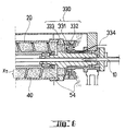
- Fig. 6
- eine Dekantierzentrifuge mit pneumatische, Flüssigkeitswehr in Schnittansicht; und
- Fig. 7
- den Ablauf des Verfahrens in einem Flussdiagramm.
- Drehzahlabsenkung,
- Nachregelung des Wehrspaltes 33 und
- Überprüfung der Wehrspaltweite
Claims (24)
- Verfahren zum Trennen eines Mehrphasengemisches (50) in wenigstens eine Flüssigkeitsphase (54) und eine Trockenphase (52) mit einer vorbestimmten Trockensubstanzkonzentration cTS,
mittels einer Dekantierzentrifuge (100), die aufweist:mit folgenden Schritten:eine ringförmige Tauchscheibe (14), die an ihrem inneren Umfang mit einer Welle (10) verbunden ist und deren Außendurchmesser kleiner ist als der Innendurchmesser einer Zentrifugentrommel (20); undwenigstens ein endseitig an der Zentrifugentrommel (20) angeordnetes Flüssigkeitswehr mit einem Wehrspalt, durch den die Flüssigkeitsphase (54) aus der Zentrifugentrommel (20) ableitbar ist, und mit einer Teichtiefeneinstellvorrichtung, mit der die Teichtiefe xT der in der Zentrifugentrommel (20) rotierenden Flüssigkeitsphase einstellbar ist,a) Anlaufen der Zentrifugentrommel (20) auf eine Starttrommeldrehzahl nZ,1 und Einstellen der Teichtiefe xT auf eine Startteichtiefe xT,1;b) Einleiten des Mehrphasengemisches (50) in die rotierende Zentrifugentrommel (20);c) Abzug der Trockenphase (52) durch die wenigstens eine Trockensubstanzaustragsausnehmung (22) und Abzug der Flüssigkeitsphase (54) durch den Wehrspalt (33);d) Regeln der Teichtiefe xT mittels der Teichtiefeneinstellvorrichtung in Abhängigkeit von der Trockensubstanzkonzentration cTS in der abgezogenen Trockenphase (52) bis zum Erreichen einer vorgegebenen Soll-Trockensubstanzkonzentration cTS,1;
gekennzeichnet durch folgende Schrittee) Festlegen eines Teichtiefentoleranzbereichs mit einer unteren Teichtiefe xT,U und einer oberen Teichtiefe xT,O;f) Vergleichen der eingeregelten Teichtiefe xW mit dem Teichtiefentoleranzbereich und fortwährende Durchführung der Schritte b) bis f) bei einer innerhalb des Teichtiefentoleranzbereiches liegenden Teichtiefe xT;g) Erhöhen der Zentrifugentrommeldrehzahl nZ um einen Drehzahlstufenwert ΔnZ bei einer Teichtiefe xT, die kleiner ist als die untere Teichtiefe xT,U, oder Absenken der Zentrifugentrommeldrehzahl nZ um einen Drehzahlstufenwert ΔnZ bei einer Teichtiefe xT, die größer ist als die obere Teichtiefe xT,O;h) Nachregeln der Teichtiefe xT in Abhängigkeit von der Trockensubstanzkonzentration cTS in der abgezogenen Trockenphase (52) bis zum Erreichen einer vorgegebenen Soll-Trockensubstanzkonzentration cTS,0;i) Vergleich der nachgeregelten Teichtiefe xT mit einem vorgegebenen Teichtiefentoleranzbereich und Wiederholung der Schritte f) bis i) bei einer außerhalb des Teichtiefentoleranzbereiches liegenden Teichtiefe xT unter fortwährender Einleitung des Mehrphasengemisches (50) in die rotierende Zentrifugentrommel (20) und Abzug der Flüssigkeits- und Trockenphase (54, 52). - Verfahren nach Anspruch 1, dadurch gekennzeichnet, dass eine Dekantierzentrifuge (100) verwendet wird, deren Flüssigkeitswehr (30) aus einer Wehrplatte (32) mit wenigstens einer Flüssigkeitsausnehmung und aus einer Drosselplatte (34) besteht, die ortsfest unter Ausbildung eines Wehrspaltes (33) gegenüber der Wehrplatte (32) gelagert und axial verschiebbar ist und dass die Teichtiefe XT über eine Vergrößerung der Wehrspaltweite xW abzusenken und über eine Verringerung der Wehrspaltweite xW zu erhöhen ist, wobei dem Teichtiefentoleranzbereich ein entsprechender Wehrspaltweitentoleranzbereich mit einer unteren Wehrspaltweite XW,U und einer oberen Wehrspaltweite xW,O zugeordnet ist.
- Verfahren nach Anspruch 2, dadurch gekennzeichnet, dass als Mittelpunkt des Wehrspaltweitentoleranzbereiches (37) die Hälfte der maximalen Wehrspaltweite xW,max gewählt wird, bei welcher gerade keine Benetzung der Drosselplatte (34) durch die aus dem Wehrspalt (33) austretende Flüssigkeitsphase (54) mehr stattfindet.
- Verfahren nach Anspruch 2, dadurch gekennzeichnet, dass als Mittelpunkt des Wehrspaltweitentoleranzbereiches (37) die in Schritt d) eingeregelte Wehrspaltweite xW gewählt wird.
- Verfahren nach einem der Ansprüche 2 bis 4, dadurch gekennzeichnet, dass in Schritt a) zur Einstellung der Startteichtiefe xT,1 eine Startwehrspaltweite xW,1 entsprechend 0,5% bis 5% der maximalen Wehrspaltweite xW,max gewählt wird.
- Verfahren nach einem der Ansprüche 2 bis 5, dadurch gekennzeichnet, dass die Breite des Wehrspaltweitentoleranzbereiches (37) zwischen einer unteren Wehrspaltweite xW,U und einer oberen Wehrspaltweite xW,O 0,5% bis 5% der maximalen Wehrspaltweite xW,max beträgt.
- Verfahren nach einem der Ansprüche 2 bis 6, dadurch gekennzeichnet, dass in Schritt d) die Wehrspaltweite xW als lineare Funktion der Zeit erhöht wird, solange eine Regelabweichung der gemessenen Trockensubstanzkonzentration cTS von der Soll-Trockensubstanzkonzentration cTS,1 mehr als 10% beträgt.
- Verfahren nach Anspruch 1, dadurch gekennzeichnet, dass eine Dekantierzentrifuge verwendet wird, deren Flüssigkeitswehr wenigstens einen sich axial erstreckenden, U-förmigen Flüssigkeitskanal aufweist, deren Eintrittsund Austrittsöffnungen zum Außenumfang des Flüssigkeitswehrs hin angeordnet sind und bei dem im Bereich der U-förmigen Biegung ein Druckgas unter Ausbildung einer hydrohermetischen Druckkammer einleitbar ist und dass die Teichtiefe xT durch Erhöhung des Gasdrucks zu erhöhen ist und durch Erniedrigen des Gasdruck abzusenken ist, wobei dem Teichtiefentoleranzbereich ein entsprechender Gasdrucktoleranzbereich mit einem unteren Gasdruck pU und einem oberen Gasdruck p0 zugeordnet ist.
- Verfahren nach Anspruch 8, dadurch gekennzeichnet, dass als Mittelpunkt des Teichtiefentoleranzbereiches die in Schritt d) eingeregelte Teichtiefe xW gewählt wird.
- Verfahren nach einem der Ansprüche 8 oder 9, dadurch gekennzeichnet, dass in Schritt a) zur Einstellung der Startteichtiefe xT,1 ein Startgasdruck p1 entsprechend 95% bis 99,5% eines maximalen Gasdrucks pmax gewählt wird.
- Verfahren nach einem der Ansprüche 8 bis 10, dadurch gekennzeichnet, dass die Breite des Gasdrucktoleranzbereiches zwischen einem unteren Gasdruck pU und einem oberen Gasdruck p0 0,5% bis 5% des maximalen Gasdrucks pmax beträgt.
- Verfahren nach einem der Ansprüche 8 bis 11, dadurch gekennzeichnet, dass in Schritt d) der Gasdruck als lineare Funktion der Zeit gesenkt wird, solange eine Regelabweichung der gemessenen Trockensubstanzkonzentration cTS von der Soll-Trockensubstanzkonzentration cTS,1 mehr als 10% beträgt.
- Verfahren nach einem der Ansprüche 1 bis 12, dadurch gekennzeichnet, dass als Starttrommeldrehzahl nZ,1 die maximal zulässige, bauartbedingte Nenndrehzahl nZ,max der Dekantierzentrifuge (100) gewählt wird.
- Verfahren nach einem der Ansprüche 1 bis 12, dadurch gekennzeichnet, dass die Starttrommeldrehzahl nZ,1 dem 0,5fachen bis 0,7fachen der maximal zulässigen, bauartbedingten Nenndrehzahl nZ,max der Dekantierzentrifuge (100) gewählt wird.
- Verfahren nach einem der Ansprüche 1 bis 14, dadurch gekennzeichnet, dass der Drehzahlstufenwert ΔnZ 1% bis 3% der maximal zulässigen, bauartbedingten Nenndrehzahl nZ,max entspricht.
- Verfahren nach einem der Ansprüche 1 bis 15, dadurch gekennzeichnet, dass der Drehzahlstufenwert ΔnZ 30...70 Umdrehungen pro Minute beträgt.
- Dekantierzentrifugensystem zur Durchführung des Verfahrens nach einem der Ansprüche 1 bis 16, mit wenigstens folgenden Einzelteilen:gekennzeichnet durcheiner Dekantierzentrifuge (100) umfassend:eine Hohlwelle (10), die wenigstens ein innenliegendes Einlaufrohr (11) aufweist;eine um die Hohlwelle (10) rotierbare Zentrifugentrommel (20), welche mit wenigstens einer in ihren Trommelmantel (21) eingebrachten Trockensubstanzaustragsausnehmung (22) versehen ist;einer ringförmigen Tauchscheibe (14), die an ihrem inneren Umfang mit der Hohlwelle (10) verbunden ist und deren Außendurchmesser kleiner ist als der Innendurchmesser des Trommelmantels (21) ;wenigstens ein endseitig an der Zentrifugentrommel (20) angeordnetes Flüssigkeitswehr mit einem Wehrspalt, durch den die Flüssigkeitsphase (54) aus der Zentrifugentrommel (20) ableitbar ist, und mit einer Teichtiefeneinstellvorrichtung, mit der die Teichtiefe xT der in der Zentrifugentrommel (20) rotierenden Flüssigkeitsphase einstellbar ist,einer Sensoreinrichtung (200) zur Messung der Trockensubstanzkonzentration cTS in der abgezogenen Trockenphase (52);eine Wehrregeleinrichtung (210) zur Regelung der Teichtiefe xT in Abhängigkeit von der Trockensubstanzkonzentration cTS;eine Drehzahlregeleinrichtung (220) zur Regelung der Trommeldrehzahl nZ in Abhängigkeit von der Teichtiefe xT und von der Trockensubstanzkonzentration cTS, mit einem Konzentrationssignaleingang (221), einem Teichtiefensignaleingang (222) und einem Drehzahlsteuersignalausgang (224).
- Dekantierzentrifugensystem nach Anspruch 17, dadurch gekennzeichnet, dass die Dekantierzentrifuge (100) eine in dem zwischen der Hohlwelle (10) und der Zentrifugentrommel (20) ausgebildeten Kreisringraum (26) angeordnete Förderschnecke (40) aufweist, die mit der Hohlwelle (10) mit einer Schneckendrehzahl nS rotierbar ist, welche gegenüber der Trommeldrehzahl nZ um eine Differenzdrehzahl ΔnS erhöhbar ist.
- Dekantierzentrifugensystem nach Anspruch 17 oder 18, dadurch gekennzeichnet, dass das Flüssigkeitswehr (30) aus einer Wehrplatte (32) mit wenigstens einer Flüssigkeitsausnehmung und aus einer Drosselplatte (34) besteht, die ortsfest unter Ausbildung eines Wehrspaltes (33) gegenüber der Wehrplatte (32) gelagert und axial verschiebbar ist.
- Dekantierzentrifugensystem nach Anspruch 17 oder 18, dadurch gekennzeichnet, dass das Flüssigkeitswehr (330) wenigstens einen sich axial erstreckenden, U-förmigen Flüssigkeitskanal aufweist, deren Eintritts- und Austrittsöffnungen (331, 332) zum Außenumfang des Flüssigkeitswehrs (330) hin angeordnet sind und bei dem im Bereich einer U-förmigen Biegung (333) Druckgas unter Ausbildung einer hydrohermetischen Druckkammer über eine Druckgasleitung (334) einleitbar ist.
- Dekantierzentrifugensystem nach einem der Ansprüche 17 bis 20, dadurch gekennzeichnet, dass die Drehzahlregeleinrichtung (220) während der Regelung der Teichtiefe xT durch die Wehrregeleinrichtung (210) bis zum Erreichen einer vorgegebenen Trockensubstanzkonzentration cTS mittels einer Deaktivierungseinrichtung (215) deaktivierbar ist.
- Dekantierzentrifugensystem (100) nach einem der Ansprüche 17 bis 21, dadurch gekennzeichnet, dass die Wehrregeleinrichtung (210) ein PI-Regler oder ein PID-Regler ist.
- Dekantierzentrifuge (100) nach einem der Ansprüche 17 bis 22, dadurch gekennzeichnet, dass die Drehzahlregeleinrichtung (220) ein Schrittregler ist, der einen Teichtiefensignaleingang (222), eine Konzentrationssignaleingang (221) und einen Drehzahlsteuersignalausgang (224) aufweist.
- Dekantierzentrifuge (100) nach einem der Ansprüche 17 bis 23, dadurch gekennzeichnet, dass der Teichtiefensignaleingang (221) der Drehzahlregeleinrichtung (220) und der Wehrsteuersignalausgang (214) der Wehrregeleinrichtung (210) direkt miteinander verbunden sind.
Priority Applications (6)
| Application Number | Priority Date | Filing Date | Title |
|---|---|---|---|
| DE50102530T DE50102530D1 (de) | 2001-02-08 | 2001-02-08 | Verfahren zum Trennen eines Mehrphasengemisches und Dekantierzentrifungensystem zur Durchführung des Verfahrens |
| AT01102962T ATE268644T1 (de) | 2001-02-08 | 2001-02-08 | Verfahren zum trennen eines mehrphasengemisches und dekantierzentrifungensystem zur durchführung des verfahrens |
| EP01102962A EP1232794B1 (de) | 2001-02-08 | 2001-02-08 | Verfahren zum Trennen eines Mehrphasengemisches und Dekantierzentrifungensystem zur Durchführung des Verfahrens |
| DK01102962T DK1232794T3 (da) | 2001-02-08 | 2001-02-08 | Fremgangsmåde til adskillelse af en flerfaseblanding og et dekanteringscentrifugesystem til udövelse af fremgangsmåden |
| US10/467,640 US7115202B2 (en) | 2001-02-08 | 2002-02-05 | Method for the separation of multi-phase mixture and decanting centrifuge system for carrying out said method |
| PCT/EP2002/001148 WO2002062483A1 (de) | 2001-02-08 | 2002-02-05 | Verfahren zum trennen eines mehrphasengemisches und dekantierzentrifugensystem zur durchführung des verfahrens |
Applications Claiming Priority (1)
| Application Number | Priority Date | Filing Date | Title |
|---|---|---|---|
| EP01102962A EP1232794B1 (de) | 2001-02-08 | 2001-02-08 | Verfahren zum Trennen eines Mehrphasengemisches und Dekantierzentrifungensystem zur Durchführung des Verfahrens |
Publications (2)
| Publication Number | Publication Date |
|---|---|
| EP1232794A1 true EP1232794A1 (de) | 2002-08-21 |
| EP1232794B1 EP1232794B1 (de) | 2004-06-09 |
Family
ID=8176431
Family Applications (1)
| Application Number | Title | Priority Date | Filing Date |
|---|---|---|---|
| EP01102962A Expired - Lifetime EP1232794B1 (de) | 2001-02-08 | 2001-02-08 | Verfahren zum Trennen eines Mehrphasengemisches und Dekantierzentrifungensystem zur Durchführung des Verfahrens |
Country Status (6)
| Country | Link |
|---|---|
| US (1) | US7115202B2 (de) |
| EP (1) | EP1232794B1 (de) |
| AT (1) | ATE268644T1 (de) |
| DE (1) | DE50102530D1 (de) |
| DK (1) | DK1232794T3 (de) |
| WO (1) | WO2002062483A1 (de) |
Cited By (3)
| Publication number | Priority date | Publication date | Assignee | Title |
|---|---|---|---|---|
| WO2003099446A1 (de) * | 2002-05-29 | 2003-12-04 | Westfalia Separator Ag | Vollmantel-schneckenzentrifuge mit schälscheibe und hydrohermetischer abdichtun g sowie verfahren zu deren betrieb |
| US7074173B2 (en) | 2002-05-08 | 2006-07-11 | Westfalia Separator Ag | Centrifuge having a centrifugal drum and a groove including a seal |
| WO2023135051A1 (de) * | 2022-01-11 | 2023-07-20 | Gea Westfalia Separator Group Gmbh | Vollmantel-schneckenzentrifuge und verfahren zur regelung des trennprozesses der vollmantel-schneckenzentrifuge |
Families Citing this family (7)
| Publication number | Priority date | Publication date | Assignee | Title |
|---|---|---|---|---|
| DE10336350B4 (de) | 2003-08-08 | 2007-10-31 | Westfalia Separator Ag | Vollmantel-Schneckenzentrifuge, mit Schälscheibe |
| DE102005027553A1 (de) * | 2005-06-14 | 2006-12-28 | Westfalia Separator Ag | Drei-Phasen-Vollmantel-Schneckenzentrifuge und Verfahren zur Regelung des Trennprozesses |
| CN101189068B (zh) | 2006-05-11 | 2011-09-28 | 威斯特伐利亚分离器股份公司 | 三相分离器及其应用和三相分离方法 |
| BRPI0917414A2 (pt) | 2008-08-15 | 2015-12-01 | M Il L C | centrífuga |
| SE534386C2 (sv) | 2009-10-29 | 2011-08-02 | Alfa Laval Corp Ab | Centrifugalseparator samt metod för separering av fasta partiklar |
| CN115672576B (zh) * | 2022-11-14 | 2023-08-22 | 江苏东邦机械有限公司 | 一种基于模糊自适应的卧螺离心机双闭环运行控制系统 |
| CN119634069A (zh) * | 2025-01-09 | 2025-03-18 | 北京金隅琉水环保科技有限公司 | 一种应用于离心机的运行状态控制方法及离心机 |
Citations (5)
| Publication number | Priority date | Publication date | Assignee | Title |
|---|---|---|---|---|
| DE1951574A1 (de) * | 1968-10-15 | 1970-04-23 | Bird Machine Co | Zentrifugiereinrichtung |
| US4303192A (en) * | 1979-07-05 | 1981-12-01 | Hide Katsume | Full jacket-worm centrifuge |
| DE4320265A1 (de) * | 1993-06-18 | 1994-12-22 | Westfalia Separator Ag | Wehr zum Einstellen von Flüssigkeitsspiegeln in Vollmantelschleudertrommeln |
| DE19500600C1 (de) * | 1995-01-11 | 1996-02-08 | Westfalia Separator Ag | Vollmantelzentrifuge |
| WO1997020634A1 (en) * | 1995-12-01 | 1997-06-12 | Baker Hughes Incorporated | Method and apparatus for controlling and monitoring continuous feed centrifuge |
Family Cites Families (1)
| Publication number | Priority date | Publication date | Assignee | Title |
|---|---|---|---|---|
| US6368264B1 (en) | 1999-03-29 | 2002-04-09 | M-I L.L.C. | Centrifuge control system and method with operation monitoring and pump control |
-
2001
- 2001-02-08 AT AT01102962T patent/ATE268644T1/de not_active IP Right Cessation
- 2001-02-08 DE DE50102530T patent/DE50102530D1/de not_active Expired - Lifetime
- 2001-02-08 EP EP01102962A patent/EP1232794B1/de not_active Expired - Lifetime
- 2001-02-08 DK DK01102962T patent/DK1232794T3/da active
-
2002
- 2002-02-05 US US10/467,640 patent/US7115202B2/en not_active Expired - Fee Related
- 2002-02-05 WO PCT/EP2002/001148 patent/WO2002062483A1/de not_active Ceased
Patent Citations (5)
| Publication number | Priority date | Publication date | Assignee | Title |
|---|---|---|---|---|
| DE1951574A1 (de) * | 1968-10-15 | 1970-04-23 | Bird Machine Co | Zentrifugiereinrichtung |
| US4303192A (en) * | 1979-07-05 | 1981-12-01 | Hide Katsume | Full jacket-worm centrifuge |
| DE4320265A1 (de) * | 1993-06-18 | 1994-12-22 | Westfalia Separator Ag | Wehr zum Einstellen von Flüssigkeitsspiegeln in Vollmantelschleudertrommeln |
| DE19500600C1 (de) * | 1995-01-11 | 1996-02-08 | Westfalia Separator Ag | Vollmantelzentrifuge |
| WO1997020634A1 (en) * | 1995-12-01 | 1997-06-12 | Baker Hughes Incorporated | Method and apparatus for controlling and monitoring continuous feed centrifuge |
Cited By (8)
| Publication number | Priority date | Publication date | Assignee | Title |
|---|---|---|---|---|
| US7074173B2 (en) | 2002-05-08 | 2006-07-11 | Westfalia Separator Ag | Centrifuge having a centrifugal drum and a groove including a seal |
| WO2003099446A1 (de) * | 2002-05-29 | 2003-12-04 | Westfalia Separator Ag | Vollmantel-schneckenzentrifuge mit schälscheibe und hydrohermetischer abdichtun g sowie verfahren zu deren betrieb |
| DE10223802A1 (de) * | 2002-05-29 | 2003-12-18 | Westfalia Separator Ag | Vollmantel-Schneckenzentrifuge und Verfahren zu deren Betrieb |
| DE10223802B4 (de) * | 2002-05-29 | 2005-06-09 | Westfalia Separator Ag | Vollmantel-Schneckenzentrifuge |
| US7056273B2 (en) | 2002-05-29 | 2006-06-06 | Westfalia Separator Ag | Solid bowl screw centrifuge comprising a peeling disk, and method for the operation thereof |
| AU2003240718B2 (en) * | 2002-05-29 | 2008-10-02 | Westfalia Separator Ag | Solid bowl screw centrifuge comprising a peeling disk, and method for the operation thereof |
| WO2023135051A1 (de) * | 2022-01-11 | 2023-07-20 | Gea Westfalia Separator Group Gmbh | Vollmantel-schneckenzentrifuge und verfahren zur regelung des trennprozesses der vollmantel-schneckenzentrifuge |
| AU2023207411B2 (en) * | 2022-01-11 | 2026-01-08 | Gea Westfalia Separator Group Gmbh | Solid bowl centrifuge and method for controlling the separation process of the solid bowl centrifuge |
Also Published As
| Publication number | Publication date |
|---|---|
| DK1232794T3 (da) | 2004-10-25 |
| US7115202B2 (en) | 2006-10-03 |
| DE50102530D1 (de) | 2004-07-15 |
| EP1232794B1 (de) | 2004-06-09 |
| US20040219065A1 (en) | 2004-11-04 |
| WO2002062483A1 (de) | 2002-08-15 |
| ATE268644T1 (de) | 2004-06-15 |
Similar Documents
| Publication | Publication Date | Title |
|---|---|---|
| DE69706716T2 (de) | Dekantierzentrifuge und zugehöriges Verfahren zum Erzeugen von Feststoff mit reduziertem Feuchtigkeitsgehalt und hohem Durchsatz | |
| EP1232794B1 (de) | Verfahren zum Trennen eines Mehrphasengemisches und Dekantierzentrifungensystem zur Durchführung des Verfahrens | |
| EP0702599B1 (de) | Wehr für vollmantelschleudertrommeln | |
| DE3022148A1 (de) | Vollmantel-schneckenzentrifuge | |
| EP2162225A1 (de) | Drei-phasen-trennseparator | |
| DE1925001A1 (de) | Zentrifuge | |
| DE10156201C1 (de) | Verfahren und Behälter zum Stapeln von hochkonsistentem Papierfaserstoff | |
| WO1991018659A1 (de) | Verfahren und vorrichtung zur mechanischen abscheidung von feststoffen aus einem fluid | |
| EP1468744A1 (de) | Schubzentrifuge mit rotierbarem Trichter zur Vorbeschleunigung des Gemisches | |
| DE102006006178A1 (de) | Vollmantel-Schneckenzentrifuge und Verfahren zu deren Betrieb | |
| DE3135509A1 (de) | Verfahren und vorrichtung zum vermahlen von faserigem ausgangsgut in mahlapparaten der doppelumlaufscheiben-bauart | |
| EP1280606A1 (de) | Vollmantelzentrifuge zur trennung von feststoff-flüssigkeitsgemischen | |
| EP4331827B1 (de) | Vorrichtung zum entwässern und verdichten von pressgut sowie verfahren zum betreiben einer solchen vorrichtung | |
| DE60124554T2 (de) | Zentrifugalabscheider | |
| WO2004094066A1 (de) | Zentrifuge mit hydraulischer differenzdrehzahlbestimmung | |
| WO2025032043A1 (de) | Vollmantel-zentrifuge | |
| DE19962645C2 (de) | Wehreinrichtung für eine Zentrifuge | |
| DE2657986C3 (de) | Verstelleinrichtung für eine Blechrichtmaschine zur Einstellung des Richtspalts | |
| EP4347134B1 (de) | Vollmantel-schneckenzentrifuge | |
| DE2208549B2 (de) | Verfahren und Vorrichtung zum Reinigen und Fraktionieren von Materialsuspensionen | |
| EP0711607B1 (de) | Verfahren zum Betrieb von Schneckenzentrifugen | |
| DE19822144B4 (de) | Druckbehandlungswalze | |
| EP3801814B1 (de) | Scheibenfilter | |
| DE4408539A1 (de) | Schneckenpresse | |
| DE69505555T2 (de) | Vorrichtung zur axialen ausrichtung des zylindermantels in einer hydrostatischen durchbiegungswalze mit selbsttätiger lastregulierung |
Legal Events
| Date | Code | Title | Description |
|---|---|---|---|
| PUAI | Public reference made under article 153(3) epc to a published international application that has entered the european phase |
Free format text: ORIGINAL CODE: 0009012 |
|
| 17P | Request for examination filed |
Effective date: 20010308 |
|
| AK | Designated contracting states |
Kind code of ref document: A1 Designated state(s): AT BE CH CY DE DK ES FI FR GB GR IE IT LI LU MC NL PT SE TR |
|
| AX | Request for extension of the european patent |
Free format text: AL;LT;LV;MK;RO;SI |
|
| 17Q | First examination report despatched |
Effective date: 20030213 |
|
| AKX | Designation fees paid |
Designated state(s): AT BE CH CY DE DK ES FI FR GB GR IE IT LI LU MC NL PT SE TR |
|
| RAP1 | Party data changed (applicant data changed or rights of an application transferred) |
Owner name: WESTFALIA SEPARATOR AG |
|
| GRAP | Despatch of communication of intention to grant a patent |
Free format text: ORIGINAL CODE: EPIDOSNIGR1 |
|
| GRAP | Despatch of communication of intention to grant a patent |
Free format text: ORIGINAL CODE: EPIDOSNIGR1 |
|
| GRAS | Grant fee paid |
Free format text: ORIGINAL CODE: EPIDOSNIGR3 |
|
| GRAA | (expected) grant |
Free format text: ORIGINAL CODE: 0009210 |
|
| AK | Designated contracting states |
Kind code of ref document: B1 Designated state(s): AT BE CH CY DE DK ES FI FR GB GR IE IT LI LU MC NL PT SE TR |
|
| PG25 | Lapsed in a contracting state [announced via postgrant information from national office to epo] |
Ref country code: TR Free format text: LAPSE BECAUSE OF FAILURE TO SUBMIT A TRANSLATION OF THE DESCRIPTION OR TO PAY THE FEE WITHIN THE PRESCRIBED TIME-LIMIT Effective date: 20040609 Ref country code: IE Free format text: LAPSE BECAUSE OF FAILURE TO SUBMIT A TRANSLATION OF THE DESCRIPTION OR TO PAY THE FEE WITHIN THE PRESCRIBED TIME-LIMIT Effective date: 20040609 Ref country code: FI Free format text: LAPSE BECAUSE OF FAILURE TO SUBMIT A TRANSLATION OF THE DESCRIPTION OR TO PAY THE FEE WITHIN THE PRESCRIBED TIME-LIMIT Effective date: 20040609 Ref country code: NL Free format text: LAPSE BECAUSE OF FAILURE TO SUBMIT A TRANSLATION OF THE DESCRIPTION OR TO PAY THE FEE WITHIN THE PRESCRIBED TIME-LIMIT Effective date: 20040609 |
|
| REG | Reference to a national code |
Ref country code: GB Ref legal event code: FG4D Free format text: NOT ENGLISH |
|
| REG | Reference to a national code |
Ref country code: CH Ref legal event code: EP |
|
| REG | Reference to a national code |
Ref country code: SE Ref legal event code: TRGR |
|
| GBT | Gb: translation of ep patent filed (gb section 77(6)(a)/1977) |
Effective date: 20040609 |
|
| REF | Corresponds to: |
Ref document number: 50102530 Country of ref document: DE Date of ref document: 20040715 Kind code of ref document: P |
|
| REG | Reference to a national code |
Ref country code: IE Ref legal event code: FG4D Free format text: GERMAN |
|
| PG25 | Lapsed in a contracting state [announced via postgrant information from national office to epo] |
Ref country code: GR Free format text: LAPSE BECAUSE OF FAILURE TO SUBMIT A TRANSLATION OF THE DESCRIPTION OR TO PAY THE FEE WITHIN THE PRESCRIBED TIME-LIMIT Effective date: 20040909 |
|
| PG25 | Lapsed in a contracting state [announced via postgrant information from national office to epo] |
Ref country code: ES Free format text: LAPSE BECAUSE OF FAILURE TO SUBMIT A TRANSLATION OF THE DESCRIPTION OR TO PAY THE FEE WITHIN THE PRESCRIBED TIME-LIMIT Effective date: 20040920 |
|
| REG | Reference to a national code |
Ref country code: DK Ref legal event code: T3 |
|
| NLV1 | Nl: lapsed or annulled due to failure to fulfill the requirements of art. 29p and 29m of the patents act | ||
| REG | Reference to a national code |
Ref country code: IE Ref legal event code: FD4D |
|
| PG25 | Lapsed in a contracting state [announced via postgrant information from national office to epo] |
Ref country code: LU Free format text: LAPSE BECAUSE OF NON-PAYMENT OF DUE FEES Effective date: 20050208 Ref country code: CY Free format text: LAPSE BECAUSE OF FAILURE TO SUBMIT A TRANSLATION OF THE DESCRIPTION OR TO PAY THE FEE WITHIN THE PRESCRIBED TIME-LIMIT Effective date: 20050208 Ref country code: AT Free format text: LAPSE BECAUSE OF NON-PAYMENT OF DUE FEES Effective date: 20050208 |
|
| PG25 | Lapsed in a contracting state [announced via postgrant information from national office to epo] |
Ref country code: LI Free format text: LAPSE BECAUSE OF NON-PAYMENT OF DUE FEES Effective date: 20050228 Ref country code: BE Free format text: LAPSE BECAUSE OF NON-PAYMENT OF DUE FEES Effective date: 20050228 Ref country code: MC Free format text: LAPSE BECAUSE OF NON-PAYMENT OF DUE FEES Effective date: 20050228 Ref country code: CH Free format text: LAPSE BECAUSE OF NON-PAYMENT OF DUE FEES Effective date: 20050228 |
|
| ET | Fr: translation filed | ||
| PLBE | No opposition filed within time limit |
Free format text: ORIGINAL CODE: 0009261 |
|
| STAA | Information on the status of an ep patent application or granted ep patent |
Free format text: STATUS: NO OPPOSITION FILED WITHIN TIME LIMIT |
|
| 26N | No opposition filed |
Effective date: 20050310 |
|
| BERE | Be: lapsed |
Owner name: *WESTFALIA SEPARATOR A.G. Effective date: 20050228 |
|
| REG | Reference to a national code |
Ref country code: CH Ref legal event code: PL |
|
| BERE | Be: lapsed |
Owner name: *WESTFALIA SEPARATOR A.G. Effective date: 20050228 |
|
| PG25 | Lapsed in a contracting state [announced via postgrant information from national office to epo] |
Ref country code: PT Free format text: LAPSE BECAUSE OF NON-PAYMENT OF DUE FEES Effective date: 20041109 |
|
| REG | Reference to a national code |
Ref country code: DE Ref legal event code: R082 Ref document number: 50102530 Country of ref document: DE |
|
| REG | Reference to a national code |
Ref country code: DE Ref legal event code: R081 Ref document number: 50102530 Country of ref document: DE Owner name: GEA MECHANICAL EQUIPMENT GMBH, DE Free format text: FORMER OWNER: WESTFALIA SEPARATOR AG, 59302 OELDE, DE Effective date: 20110922 Ref country code: DE Ref legal event code: R081 Ref document number: 50102530 Country of ref document: DE Owner name: GEA MECHANICAL EQUIPMENT GMBH, DE Free format text: FORMER OWNER: GEA WESTFALIA SEPARATOR GMBH, 59302 OELDE, DE Effective date: 20140507 |
|
| REG | Reference to a national code |
Ref country code: FR Ref legal event code: PLFP Year of fee payment: 16 |
|
| PGFP | Annual fee paid to national office [announced via postgrant information from national office to epo] |
Ref country code: DE Payment date: 20160229 Year of fee payment: 16 Ref country code: DK Payment date: 20160222 Year of fee payment: 16 Ref country code: IT Payment date: 20160226 Year of fee payment: 16 |
|
| PGFP | Annual fee paid to national office [announced via postgrant information from national office to epo] |
Ref country code: GB Payment date: 20160223 Year of fee payment: 16 Ref country code: SE Payment date: 20160223 Year of fee payment: 16 Ref country code: FR Payment date: 20160224 Year of fee payment: 16 |
|
| REG | Reference to a national code |
Ref country code: DE Ref legal event code: R119 Ref document number: 50102530 Country of ref document: DE |
|
| REG | Reference to a national code |
Ref country code: DK Ref legal event code: EBP Effective date: 20170228 |
|
| REG | Reference to a national code |
Ref country code: SE Ref legal event code: EUG |
|
| GBPC | Gb: european patent ceased through non-payment of renewal fee |
Effective date: 20170208 |
|
| PG25 | Lapsed in a contracting state [announced via postgrant information from national office to epo] |
Ref country code: SE Free format text: LAPSE BECAUSE OF NON-PAYMENT OF DUE FEES Effective date: 20170209 |
|
| REG | Reference to a national code |
Ref country code: FR Ref legal event code: ST Effective date: 20171031 |
|
| PG25 | Lapsed in a contracting state [announced via postgrant information from national office to epo] |
Ref country code: FR Free format text: LAPSE BECAUSE OF NON-PAYMENT OF DUE FEES Effective date: 20170228 Ref country code: DK Free format text: LAPSE BECAUSE OF NON-PAYMENT OF DUE FEES Effective date: 20170228 Ref country code: DE Free format text: LAPSE BECAUSE OF NON-PAYMENT OF DUE FEES Effective date: 20170901 |
|
| PG25 | Lapsed in a contracting state [announced via postgrant information from national office to epo] |
Ref country code: IT Free format text: LAPSE BECAUSE OF NON-PAYMENT OF DUE FEES Effective date: 20170208 Ref country code: GB Free format text: LAPSE BECAUSE OF NON-PAYMENT OF DUE FEES Effective date: 20170208 |