EP1232827A2 - Torche à arc de plasma avec courant de gaz amélioré - Google Patents
Torche à arc de plasma avec courant de gaz amélioré Download PDFInfo
- Publication number
- EP1232827A2 EP1232827A2 EP01309194A EP01309194A EP1232827A2 EP 1232827 A2 EP1232827 A2 EP 1232827A2 EP 01309194 A EP01309194 A EP 01309194A EP 01309194 A EP01309194 A EP 01309194A EP 1232827 A2 EP1232827 A2 EP 1232827A2
- Authority
- EP
- European Patent Office
- Prior art keywords
- gas
- holder
- electrode
- torch
- nozzle
- Prior art date
- Legal status (The legal status is an assumption and is not a legal conclusion. Google has not performed a legal analysis and makes no representation as to the accuracy of the status listed.)
- Granted
Links
- 238000004891 communication Methods 0.000 claims description 16
- 239000012530 fluid Substances 0.000 claims description 16
- 230000001105 regulatory effect Effects 0.000 claims description 4
- 238000007599 discharging Methods 0.000 claims description 3
- 239000007789 gas Substances 0.000 description 113
- 238000005520 cutting process Methods 0.000 description 13
- 239000003570 air Substances 0.000 description 12
- RYGMFSIKBFXOCR-UHFFFAOYSA-N Copper Chemical compound [Cu] RYGMFSIKBFXOCR-UHFFFAOYSA-N 0.000 description 9
- 238000001816 cooling Methods 0.000 description 9
- 229910052802 copper Inorganic materials 0.000 description 9
- 239000010949 copper Substances 0.000 description 9
- 239000000463 material Substances 0.000 description 7
- 238000012546 transfer Methods 0.000 description 6
- 230000006378 damage Effects 0.000 description 5
- 238000000034 method Methods 0.000 description 5
- 230000007423 decrease Effects 0.000 description 4
- 229910052751 metal Inorganic materials 0.000 description 4
- 239000002184 metal Substances 0.000 description 4
- 229910000881 Cu alloy Inorganic materials 0.000 description 3
- 229910045601 alloy Inorganic materials 0.000 description 3
- 239000000956 alloy Substances 0.000 description 3
- 230000008901 benefit Effects 0.000 description 3
- IJGRMHOSHXDMSA-UHFFFAOYSA-N Atomic nitrogen Chemical compound N#N IJGRMHOSHXDMSA-UHFFFAOYSA-N 0.000 description 2
- PXHVJJICTQNCMI-UHFFFAOYSA-N Nickel Chemical compound [Ni] PXHVJJICTQNCMI-UHFFFAOYSA-N 0.000 description 2
- KDLHZDBZIXYQEI-UHFFFAOYSA-N Palladium Chemical compound [Pd] KDLHZDBZIXYQEI-UHFFFAOYSA-N 0.000 description 2
- QCWXUUIWCKQGHC-UHFFFAOYSA-N Zirconium Chemical compound [Zr] QCWXUUIWCKQGHC-UHFFFAOYSA-N 0.000 description 2
- QVGXLLKOCUKJST-UHFFFAOYSA-N atomic oxygen Chemical compound [O] QVGXLLKOCUKJST-UHFFFAOYSA-N 0.000 description 2
- 230000015572 biosynthetic process Effects 0.000 description 2
- 239000004020 conductor Substances 0.000 description 2
- 229910052735 hafnium Inorganic materials 0.000 description 2
- VBJZVLUMGGDVMO-UHFFFAOYSA-N hafnium atom Chemical compound [Hf] VBJZVLUMGGDVMO-UHFFFAOYSA-N 0.000 description 2
- 239000012212 insulator Substances 0.000 description 2
- 238000004519 manufacturing process Methods 0.000 description 2
- 239000007769 metal material Substances 0.000 description 2
- 238000012986 modification Methods 0.000 description 2
- 230000004048 modification Effects 0.000 description 2
- 239000001301 oxygen Substances 0.000 description 2
- 229910052760 oxygen Inorganic materials 0.000 description 2
- BASFCYQUMIYNBI-UHFFFAOYSA-N platinum Chemical compound [Pt] BASFCYQUMIYNBI-UHFFFAOYSA-N 0.000 description 2
- WFKWXMTUELFFGS-UHFFFAOYSA-N tungsten Chemical compound [W] WFKWXMTUELFFGS-UHFFFAOYSA-N 0.000 description 2
- 229910052721 tungsten Inorganic materials 0.000 description 2
- 239000010937 tungsten Substances 0.000 description 2
- 238000003466 welding Methods 0.000 description 2
- 229910052726 zirconium Inorganic materials 0.000 description 2
- QPLDLSVMHZLSFG-UHFFFAOYSA-N Copper oxide Chemical compound [Cu]=O QPLDLSVMHZLSFG-UHFFFAOYSA-N 0.000 description 1
- 239000005751 Copper oxide Substances 0.000 description 1
- 239000004593 Epoxy Substances 0.000 description 1
- BQCADISMDOOEFD-UHFFFAOYSA-N Silver Chemical compound [Ag] BQCADISMDOOEFD-UHFFFAOYSA-N 0.000 description 1
- 230000009471 action Effects 0.000 description 1
- 238000000137 annealing Methods 0.000 description 1
- 150000001875 compounds Chemical class 0.000 description 1
- 239000000356 contaminant Substances 0.000 description 1
- 238000007796 conventional method Methods 0.000 description 1
- 239000000112 cooling gas Substances 0.000 description 1
- 229910000431 copper oxide Inorganic materials 0.000 description 1
- 238000010891 electric arc Methods 0.000 description 1
- 239000012777 electrically insulating material Substances 0.000 description 1
- 230000005611 electricity Effects 0.000 description 1
- PCHJSUWPFVWCPO-UHFFFAOYSA-N gold Chemical compound [Au] PCHJSUWPFVWCPO-UHFFFAOYSA-N 0.000 description 1
- 229910052737 gold Inorganic materials 0.000 description 1
- 239000010931 gold Substances 0.000 description 1
- 239000003779 heat-resistant material Substances 0.000 description 1
- 229910052741 iridium Inorganic materials 0.000 description 1
- GKOZUEZYRPOHIO-UHFFFAOYSA-N iridium atom Chemical compound [Ir] GKOZUEZYRPOHIO-UHFFFAOYSA-N 0.000 description 1
- 238000012423 maintenance Methods 0.000 description 1
- 238000002844 melting Methods 0.000 description 1
- 230000008018 melting Effects 0.000 description 1
- 150000002739 metals Chemical class 0.000 description 1
- 238000013508 migration Methods 0.000 description 1
- 230000005012 migration Effects 0.000 description 1
- 229910052759 nickel Inorganic materials 0.000 description 1
- 229910052757 nitrogen Inorganic materials 0.000 description 1
- 230000001590 oxidative effect Effects 0.000 description 1
- 229910052763 palladium Inorganic materials 0.000 description 1
- 230000037361 pathway Effects 0.000 description 1
- 229910052697 platinum Inorganic materials 0.000 description 1
- 238000003825 pressing Methods 0.000 description 1
- 230000002441 reversible effect Effects 0.000 description 1
- 229910052703 rhodium Inorganic materials 0.000 description 1
- 239000010948 rhodium Substances 0.000 description 1
- MHOVAHRLVXNVSD-UHFFFAOYSA-N rhodium atom Chemical compound [Rh] MHOVAHRLVXNVSD-UHFFFAOYSA-N 0.000 description 1
- 229910052709 silver Inorganic materials 0.000 description 1
- 239000004332 silver Substances 0.000 description 1
- 238000004381 surface treatment Methods 0.000 description 1
- 229920001187 thermosetting polymer Polymers 0.000 description 1
- 238000013022 venting Methods 0.000 description 1
- XLYOFNOQVPJJNP-UHFFFAOYSA-N water Substances O XLYOFNOQVPJJNP-UHFFFAOYSA-N 0.000 description 1
Images

Classifications
-
- B—PERFORMING OPERATIONS; TRANSPORTING
- B23—MACHINE TOOLS; METAL-WORKING NOT OTHERWISE PROVIDED FOR
- B23K—SOLDERING OR UNSOLDERING; WELDING; CLADDING OR PLATING BY SOLDERING OR WELDING; CUTTING BY APPLYING HEAT LOCALLY, e.g. FLAME CUTTING; WORKING BY LASER BEAM
- B23K10/00—Welding or cutting by means of a plasma
-
- H—ELECTRICITY
- H05—ELECTRIC TECHNIQUES NOT OTHERWISE PROVIDED FOR
- H05H—PLASMA TECHNIQUE; PRODUCTION OF ACCELERATED ELECTRICALLY-CHARGED PARTICLES OR OF NEUTRONS; PRODUCTION OR ACCELERATION OF NEUTRAL MOLECULAR OR ATOMIC BEAMS
- H05H1/00—Generating plasma; Handling plasma
- H05H1/24—Generating plasma
- H05H1/26—Plasma torches
- H05H1/32—Plasma torches using an arc
- H05H1/34—Details, e.g. electrodes, nozzles
-
- H—ELECTRICITY
- H05—ELECTRIC TECHNIQUES NOT OTHERWISE PROVIDED FOR
- H05H—PLASMA TECHNIQUE; PRODUCTION OF ACCELERATED ELECTRICALLY-CHARGED PARTICLES OR OF NEUTRONS; PRODUCTION OR ACCELERATION OF NEUTRAL MOLECULAR OR ATOMIC BEAMS
- H05H1/00—Generating plasma; Handling plasma
- H05H1/24—Generating plasma
- H05H1/26—Plasma torches
- H05H1/32—Plasma torches using an arc
- H05H1/34—Details, e.g. electrodes, nozzles
- H05H1/3436—Hollow cathodes with internal coolant flow
-
- H—ELECTRICITY
- H05—ELECTRIC TECHNIQUES NOT OTHERWISE PROVIDED FOR
- H05H—PLASMA TECHNIQUE; PRODUCTION OF ACCELERATED ELECTRICALLY-CHARGED PARTICLES OR OF NEUTRONS; PRODUCTION OR ACCELERATION OF NEUTRAL MOLECULAR OR ATOMIC BEAMS
- H05H1/00—Generating plasma; Handling plasma
- H05H1/24—Generating plasma
- H05H1/26—Plasma torches
- H05H1/32—Plasma torches using an arc
- H05H1/34—Details, e.g. electrodes, nozzles
- H05H1/3442—Cathodes with inserted tip
-
- H—ELECTRICITY
- H05—ELECTRIC TECHNIQUES NOT OTHERWISE PROVIDED FOR
- H05H—PLASMA TECHNIQUE; PRODUCTION OF ACCELERATED ELECTRICALLY-CHARGED PARTICLES OR OF NEUTRONS; PRODUCTION OR ACCELERATION OF NEUTRAL MOLECULAR OR ATOMIC BEAMS
- H05H1/00—Generating plasma; Handling plasma
- H05H1/24—Generating plasma
- H05H1/26—Plasma torches
- H05H1/32—Plasma torches using an arc
- H05H1/34—Details, e.g. electrodes, nozzles
- H05H1/3478—Geometrical details
Definitions
- the present invention relates to plasma arc torches and, more particularly, to a method and apparatus for supplying a gas flow for supporting an electric arc in a plasma arc torch.
- Plasma arc torches are commonly used for the working of metal, including cutting, welding, surface treatment, melting, and annealing. Such torches include an electrode which supports an arc which extends from the electrode to a workpiece in the transferred arc mode of operation. It is also conventional to surround the arc with a swirling vortex flow of gas, and in some torch designs it is conventional to also envelop the gas and arc in a swirling jet of water.
- the electrode used in conventional torches of the described type typically comprises an elongate tubular member composed of a material of high thermal conductivity, such as copper or a copper alloy.
- the forward or discharge end of the tubular electrode includes a bottom end wall having an emissive element embedded therein, which supports the arc.
- the emissive element is composed of a material which has a relatively low work function, which is defined in the art as the potential step, measured in electron volts (ev), which permits thermionic emission from the surface of a metal at a given temperature. In view of this low work function, the element is thus capable of readily emitting electrons when an electrical potential is applied thereto.
- Commonly used emissive materials include hafnium, zirconium, tungsten, and alloys thereof.
- a nozzle surrounds the discharge end of the electrode and provides a pathway for directing the arc towards the workpiece.
- a problem associated with torches of the type described above is the short service life of the electrode, particularly when the torch is used with an oxidizing gas, such as oxygen or air. More particularly, the emissive elements of these torches often erode below the surface of the copper holder at the discharge end. Additionally, the gas tends to rapidly oxidize the copper of the electrode that surrounds the emissive element and, as the copper oxidizes, its work function decreases. As a result, a point is reached at which the oxidized copper surrounding the emissive element begins to support the arc, rather than the emissive element. When this happens, the copper oxide and the supporting copper melt, resulting in early destruction and failure of the electrode.
- an oxidizing gas such as oxygen or air.
- the air is circulated rapidly about the electrode to improve heat transfer from the arc away from the electrode.
- a conventional method for the air to be distributed in an air cooled plasma arc torch is for the air to first be used in some fashion to cool the electrode and then to be split into separate primary and secondary flows. Typically, this is accomplished by means of a gas baffle positioned between the nozzle and the electrode for splitting the flow into the primary or cutting gas flow and the secondary or shield gas flow, which helps maintain the position of the arc.
- the primary flow of the gas passes through holes in the gas baffle into a chamber defined by a primary nozzle and the electrode and is ejected by the primary nozzle, while the rest of the gas is directed out a secondary nozzle so as to surround the primary gas flow.
- the baffle splits the gas into the primary flow and secondary flow before the nozzle chamber, which limits the ability of the torch to transfer heat from the electrode and can reduce the speed of the torch, as discussed below.
- baffles also add to the cost and complexity of manufacturing and assembling the torch. More specifically, baffles are subject to failure and can occasionally be inadvertently omitted by an operator during assembly of the torch. Furthermore, baffles tend to become brittle over time and eventually develop cracks, which often lead to catastrophic failure unless the baffles are frequently replaced. Even when replaced on a regular preventative maintenance cycle, which adds further cost to the torch, human error may lead to the baffles being left out during assembly of the torch, which can damage the torch or cause the torch to operate incorrectly. In addition, baffles can also permit the arc to "jump" or track across the baffle, which can also damage the torch.
- baffles can result in a convoluted set of passages in and around the electrode through which air can pass, which can lead to migration of the arc through the passages.
- U.S. Patent No. 5,726,415 to Luo et al. discloses a plasma are torch with an electrode having an metallic holder with an emissive element positioned at a discharge end thereof.
- the torch also includes a nozzle, which in combination with the holder defines an annular gas chamber therebetween for directing a cooling gas about the electrode.
- the nozzle also defines a cylindrical exhaust port for directing a primary gas flow towards a workpiece, and bleed ports positioned in the rear portion of the nozzle for venting a majority of the gas through bores for use as a shield or secondary gas flow.
- the bleed ports bleed approximately 90% of the gas, thus leaving 10% of the gas to cool the full length of the electrode and exit the cylindrical exhaust port as the primary gas flow towards the workpiece.
- the bleed ports bleed approximately 90% of the gas, thus leaving 10% of the gas to cool the full length of the electrode and exit the cylindrical exhaust port as the primary gas flow towards the workpiece.
- U.S. Patent No. 4,558,201 to Hatch discloses a plasma arc torch having a reversible electrode that has both a forward insert and a rearward insert positioned at opposing ends thereof.
- the electrode defines a plurality of passageways for directing the gas towards a workpiece.
- gas is directed through channels around the exterior of the electrode as well as through a central passage extending along the longitudinal axis of the electrode. As the gas reaches the midpoint of the electrode, however, the gas is split into a primary flow and a secondary flow, wherein the secondary flow is directed away from the electrode around an insulator to a front portion of a chamber defined by a nozzle and the insulator.
- the primary flow is directed out a central orifice in the nozzle along with the electrical arc extending from the forward emissive insert to the workpiece.
- the gas flow is split into a primary flow and a secondary flow before the gas has traveled substantially the length of the electrode, which decreases the heat transfer capability of the gas and provides less gas pressure in the nozzle chamber, which decreases the efficiency of the torch.
- a plasma arc torch that directs a flow of gas along substantially the length of the electrode such that more gas is used to cool the torch compared to conventional torches.
- the torch of the present invention includes an electrode defining a plurality of openings positioned proximate the front end of the electrode such that all of the gas supplied to the torch is directed through the openings into a chamber defined by the electrode and the nozzle.
- the gas pressure in the nozzle chamber is increased compared to conventional torches, which allows the torch of the present invention to have a faster cutting speed.
- the torch of the present invention utilizes the openings in the electrode itself to direct the flow of gas, and not baffles as in conventional torches.
- a plasma arc torch includes an electrode having an upper tubular member defining an internal bore and a lower cup-shaped member or holder defining a central passageway in fluid communication with the internal bore of the upper tubular member.
- the front end of the holder defines a cavity for receiving an emissive insert, and the rear end defines the central passageway.
- the holder also defines a plurality of side openings that are in fluid communication with the central passageway. In one embodiment, the side openings are arranged to impart a swirling motion to the gas flowing therethrough.
- the plasma arc torch also includes a nozzle positioned proximate the front end of the holder such that a nozzle chamber is defined therebetween.
- the nozzle defines a central bore for discharging a primary flow of gas towards a workpiece, and in one embodiment also defines a plurality of secondary openings for creating a secondary flow of gas therethrough.
- the openings defined in the nozzle and holder eliminate the need for separate baffles for separating the gas flow into the primary and secondary flows.
- Safety items are also a part of the torch of the present invention. More specifically, in one embodiment a ball valve assembly is located in the internal bore of the upper tubular member of the electrode for regulating gas flow through the electrode. In this regard, the ball valve assembly acts to protect the torch from damage if a user attempts to operate the torch with portions of the torch missing, such as the holder of the electrode, by cutting off the gas flow through the torch.
- the plasma arc torch of the present invention can also include a pressure switch in fluid communication with the nozzle chamber. The pressure switch can disable the torch if the gas pressure in the torch, such as in the nozzle chamber, is below a predetermined value, which may occur if the torch is assembled incorrectly or if the torch is damaged.
- a electrode having a metallic holder wherein the holder defines a plurality of side openings and a central passageway in fluid communication therewith.
- a nozzle is positioned proximate the holder to define a nozzle chamber therebetween.
- a flow of gas is directed through the central passageway into the nozzle chamber such that all of the gas supplied into the central passageway is directed through the side openings into the nozzle chamber.
- the gas is split into at least a primary flow and a secondary flow after the flow of gas has entered the nozzle chamber, which provides greater pressure in the nozzle chamber and allows for greater cutting speeds.
- the flow of gas is directed through the central passageway a distance more than 1/2 the length of the holder before being directed through the side openings thereof. As such, more gas is available for transferring heat from the arc and electrode away from the torch.
- the flow of gas can also be directed to certain safety devices, such as the flow-regulating ball valve assembly, or to the pressure switch that is in fluid communication with the nozzle chamber.
- the torch is disabled if certain conditions occur, such as having a gas pressure in the torch that is below a predetermined value.
- the present invention provides a plasma arc torch that overcomes the disadvantages of conventional torches without sacrificing the cutting speed of the torch or the pressure realized in the nozzle chamber.
- the torch and methods of the present invention avoid the use of baffles to direct the flow of gas from the electrode to a primary flow and a secondary flow, which improves the assembly, reliability, and cost of the torch.
- FIG. 1 illustrates a preferred embodiment of a plasma arc torch, indicated generally at 10, according to the invention.
- the torch 10 comprises a torch body 20 and electrode 40 mounted within the torch body, and a handle 13 secured to the torch body, such as by press fitting over a plurality of bushings 14.
- the torch 10 further comprises a supply line 70 for directing a pressurized flow of gas through the torch body 20 and directing electrical power to the electrode 40.
- the torch 10 also includes a detecting device 80 for sensing the gas pressure in the torch body 20 and for disabling the flow of electrical current to the electrode 40 in accordance with the present invention.
- the torch body 20 comprises a generally cylindrical head portion 21 defining a discharge axis.
- the head portion 21 includes a housing 22 surrounding a portion of the electrode 40 along the discharge axis.
- the housing 22 is typically made of a hard, heat-resistant material, such as thermoset plastic or epoxy compound, which protects the components of the torch from the high heat generated during plasma arc cutting.
- the electrode 40 includes an upper tubular member 23 and a lower cup-shaped member or holder 41.
- the upper tubular member 23 defines an internal bore 24 which is coaxially aligned with the discharge axis.
- the internal bore 24 includes a valve seat 34, as discussed more fully below.
- the upper tubular member 23 is made of an electrically conductive material, preferably copper or copper alloy, such that the upper tubular member conducts an electrical current to other portions of the electrode 40.
- the upper tubular member 23 also defines a passageway 25 such that the internal bore 24 is in fluid communication with the supply line 70.
- a cap 26 is secured to the top of the upper tubular member 23 for directing gas along the discharge axis.
- the upper tubular member 23 includes an internally threaded portion 27.
- the supply line 70 comprises a hollow conduit 72 defining a gas passageway and is positioned within the torch body 20.
- the conduit 72 originates at a source of pressurized gas and terminates in the passageway 25 of the upper tubular member 23 of the electrode 40 such that the source of pressurized gas is in fluid communication with the internal bore 24.
- Supply line 70 further comprises a power supply cable 71 electrically connected to the conduit 72 and a power source such that the power source is electrically connected to the electrode 40.
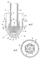
- Figure 2 illustrates one embodiment of the holder 41 of the electrode 40.
- the holder 41 is made of an electrically conductive material, preferably copper or copper alloy.
- the holder 41 has a rear end 42 defining a central passageway 43 that is in fluid communication with the internal bore 24 of the upper tubular member 23.
- the rear end 42 includes a plurality of external threads 44 suitable for threadably engaging the internally threaded portion 27 of the upper tubular member 23.
- the holder 41 also includes a front end 45 having a front face 46 and defining a front cavity or opening 47 therein.
- the holder 41 includes side walls 48 and a transverse end wall 49 that define the central passageway 43.
- the holder 41 also defines a plurality of openings 50 that are positioned in the side walls 48 adjacent the end wall 49.
- the openings 50 are located at a position less than one-half the length of the holder 41 from the front face 46 thereof.
- the openings 50 are located proximate the end wall 49 of the holder 41 at the forward end of the central passageway 43 and, according to one embodiment, are directed non-radially so that gas passing through the openings is swirled about the holder 41.
- the end wall 49 defines a plurality of channels 56 corresponding to the openings 50 for directing the gas from the central passageway 43 through the openings.
- gas is directed through the supply line 70 and into the internal bore 24 of the upper tubular member 23.
- the gas is then directed into the central passageway 43 of the holder 41 towards the openings 50 so as to cool the electrode while the torch 10 is in use.
- a channeled valve pin 51 can be positioned in the internal bore 24 and central passageway 43 for increasing the velocity of the gas therein, such as by swirling the gas. In this manner, the gas receives more contact with the electrode 40, which thereby increases the heat transfer between the electrode and the gas.
- the pin 51 can also be used as a safety device, as discussed more fully below.
- the front end 45 of the holder 41 includes an emissive element 52 disposed in the opening 47.
- the emissive element 52 acts as the cathode terminal for an electrical arc extending from the front end of the electrode 40 in the direction of a workpiece WP, as discussed more fully below.
- an electrode comprising an emissive element is disclosed in U.S. Patent No. 5,023,425 to Severance, Jr., and assigned to the assignee of the present invention.
- the emissive element 52 is composed of a material which has a relatively low work function, defined in the art as the potential step, measured in electron volts, that permits thermionic emission from the surface of a metal at a given temperature. In view of its low work function, the emissive element readily emits electrons in the presence of an electrical potential.
- Commonly used insert materials include hafnium, zirconium, tungsten, and alloys thereof.
- a relatively non-emissive separator may also be positioned about the emissive element 52 at the front end 45 of the holder 41.
- the separator is positioned about the emissive element 52 in the opening 47 of the electrode.
- the separator is composed of a metallic material having a work function which is greater than that of the material of the holder 41, and also greater than that of the material of the emissive element 52.
- the separator be composed of a metallic material having a relatively high work function.
- metals and alloys are usable for the non-emissive separator of the present invention, such as silver, gold, platinum, rhodium, iridium, palladium, nickel.
- the emissive element 52, separator, and holder 41 are flush with one another at the front face 46 of the holder.
- the torch 10 also includes a nozzle 60 positioned proximate the holder 41 of the electrode 40.
- the nozzle 60 includes an upper portion 61, a middle portion 62, and a frustoconical lower portion 63.
- the nozzle 60 is positioned about the holder 41 such that a chamber 90 is defined therebetween.
- the upper portion 61 of the nozzle 60 defines a plurality of slots 65 through which air pressure form the nozzle chamber 90 is communicated to the detecting device 80.
- the middle portion 62 of the nozzle forms a shoulder 64 with the upper portion 61 and defines a plurality of openings 66 therethrough such that the nozzle chamber 90 is in fluid communication with a shield or secondary gas flow port 91, which is defined between the nozzle 60 and an outer heat shield 74 and is in fluid communication with the ambient atmosphere (see Figure 1).
- the lower portion 63 of the nozzle 60 defines a central bore 67 for discharging gas from the nozzle chamber 90 toward the workpiece WP located adjacent the nozzle.
- the heat shield 74 which is preferably formed of an electrically insulating material, includes a metallic sleeve 92 having a transverse portion 93 at one end and threaded portion 76 at the other end.
- the threaded portion 76 threadably engages a threaded surface 79 of the housing 22, and the transverse portion 93 engages the shoulder 64 provided on the nozzle 60 to hold the nozzle in place about the holder 41 when the heat shield 74 is secured on the torch body 20.
- the heat shield 74 also defines a central opening 78 therethrough adjacent the nozzle 60 and coaxially aligned with the discharge axis such that the shield gas port flow 91 is defined between the heat shield and nozzle.
- a resilient O-ring 77 is positioned between the housing 22 and the heat shield 74 to protect the electrode 40 and nozzle 60 from external contaminants and to seal the torch body 20 when the heat shield is properly secured thereto.
- the pressure detecting device 80 comprises a hollow conduit 82 defining a gas passageway within the torch body 20. More specifically, conduit 82 originates in the head portion 21 of torch body 20, and terminates at a pressure switch (not shown) such that the pressure switch is in fluid communication with the internal bore 24 of the upper tubular member 23 and the central passageway 43 of the holder 41 via the side openings 50 and the slots 65.
- the conduit 82 and pressure switch of this type are described in U.S. Patent No. 5,681,489, which is assigned to the assignee of the present invention and incorporated herein by reference.
- a low voltage electrical circuit in the power source is closed.
- the electrical circuit opens a solenoid positioned in the power source such that the supply line 70 directs a singular, pressurized flow of gas through the conduit 72 to the head portion 21 and internal bore 24 of the upper tubular member 23.
- the pressurized gas may be any gas capable of forming a plasma flow, but preferably is air, oxygen or nitrogen.
- the gas is then directed to the central passageway 43 defined in the holder 41.
- all of the gas supplied into the central passageway 43 exits through the openings 50 positioned adjacent the end wall 49 of the holder 41 and into the nozzle chamber 90.
- the gas travels substantially the length of the electrode 40, such as to a position less than one-half the length of the electrode 40, and preferably one-half the length of the holder 41, measured along the longitudinal axis from the front face 46.
- the torch of the present invention provides improved cooling to the electrode compared to conventional torches.
- the openings 50 are preferably in a tangential formation, as shown in Figure 3. This arrangement creates a swirling pattern about the front end 45 as the gas enters the nozzle chamber 90.
- a primary flow portion of the gas is directed to the central bore 67 of the nozzle 60.
- the opening 66 defined in the middle portion 62 of the nozzle 60 allow a secondary flow portion of the gas to escape therethrough to the shield gas flow port 91.
- all of the gas present in the nozzle chamber 90 enters the nozzle chamber through the openings 50 in the holder 41. In this manner, higher nozzle pressures can be achieved, which allows for a higher cutting speed of the torch 10.
- the gas is in contact with the electrode 40 for a longer period of time compared to conventional torches, which improves cooling of the torch.
- the flow of gas is initiated by an operator pressing a control switch.
- sufficient gas pressure must be present in the torch. More specifically, when the outer heat shield 74 is properly secured about the nozzle 60 on the torch body 20, the pressure detecting device 80 senses the gas pressure in the torch body, such as in the nozzle chamber 90. According to one embodiment of the present invention, the pressure in the nozzle chamber 90 should be at least approximately 30 psi using conventional "shop" air, which is about 75 psi. If the device 80 senses sufficient gas pressure in the nozzle chamber 90 for a predetermined time, typically about three seconds, the detecting device closes, or causes to be closed, an electrical circuit to permit the power source to supply electrical current to the torch 10. In other words, as long as there is sufficient gas pressure in the nozzle chamber 90, which can be achieved by maintaining a predetermined gas flow rate through a properly assembled torch, the power source will supply electrical current to the electrode 40.
- the torch 10 also includes a ball valve assembly capable of regulating the gas through the torch.
- the assembly includes a non-conductive ball 33 of spherical geometry that is positioned in the internal bore 24 of the upper tubular member 23 and is biased by a bias member 35, such as a spring, against the valve seat 34 .
- the valve pin 51 is capable of moving and holding the ball 33 away from the valve seat 34 when the holder 41 is properly installed and engaged with the upper tubular member 23.
- the ball 33 serves as a "parts in place” feature to protect the torch body 20 from damage should the holder 41 or valve pin 51 be left out. If either is omitted, the ball 33 remains against the valve seat 34, which prevents the gas from flowing through the internal bore 24 to the central passageway 43. As a result, the lack of gas flow prevents a pressure signal from being communicated to the pressure switch via the conduit 82, which must be satisfied for the power source to deliver current to the torch 10.
- U.S. Patent No. 4,580,032 to Carkhuff which is assigned to the assignee of the present invention and incorporated herein by reference.
- the present invention provides a plasma arc torch and method of directing a flow of gas in the torch such that greater cooling of the electrode is achieved and increased cutting speeds can be realized compared to conventional torches.
- the electrode of the present invention provides a holder defining a plurality of openings proximate the front end thereof for directing all of the gas into the nozzle chamber before splitting the gas into primary and secondary flows.
- the gas is in contact with the electrode along substantially the length of the electrode before it is split, which improves cooling of the electrode.
- gas baffles are not used in assembly of the torch to separate the gas into primary and secondary flows. In this regard, the assembly time and cost of the torch are reduced, while providing an increase in nozzle chamber pressure and thus cutting speed of the torch.
Landscapes
- Physics & Mathematics (AREA)
- Engineering & Computer Science (AREA)
- Plasma & Fusion (AREA)
- Spectroscopy & Molecular Physics (AREA)
- Mechanical Engineering (AREA)
- Geometry (AREA)
- Plasma Technology (AREA)
- Arc Welding In General (AREA)
Applications Claiming Priority (2)
| Application Number | Priority Date | Filing Date | Title |
|---|---|---|---|
| US09/772,652 US6362450B1 (en) | 2001-01-30 | 2001-01-30 | Gas flow for plasma arc torch |
| US772652 | 2001-01-30 |
Publications (3)
| Publication Number | Publication Date |
|---|---|
| EP1232827A2 true EP1232827A2 (fr) | 2002-08-21 |
| EP1232827A3 EP1232827A3 (fr) | 2002-08-28 |
| EP1232827B1 EP1232827B1 (fr) | 2006-12-13 |
Family
ID=25095764
Family Applications (1)
| Application Number | Title | Priority Date | Filing Date |
|---|---|---|---|
| EP01309194A Expired - Lifetime EP1232827B1 (fr) | 2001-01-30 | 2001-10-30 | Torche à arc de plasma avec courant de gaz amélioré |
Country Status (9)
| Country | Link |
|---|---|
| US (1) | US6362450B1 (fr) |
| EP (1) | EP1232827B1 (fr) |
| JP (1) | JP3728252B2 (fr) |
| KR (1) | KR100480391B1 (fr) |
| AT (1) | ATE347965T1 (fr) |
| CA (1) | CA2361818C (fr) |
| DE (1) | DE60125140T2 (fr) |
| MX (1) | MXPA02001040A (fr) |
| TW (1) | TW506872B (fr) |
Cited By (1)
| Publication number | Priority date | Publication date | Assignee | Title |
|---|---|---|---|---|
| EP4313465A4 (fr) * | 2021-04-06 | 2024-10-16 | Ahmet Yildirim | Électrode à durée de vie étendue utilisée dans des torches de coupe à l'arc à plasma refroidies par liquide avec augmentation de surface de refroidissement par raclage de haut en bas des surfaces internes lavées par le liquide de refroidissement, par pressage de la partie inférieure, par création d'indentations et de saillies qui s'étendent en parallèle et/ou selon le même angle ainsi que par augmentation de la vitesse de transfert de chaleur instantanée par l'approche de la paroi de transfert de chaleur |
Families Citing this family (26)
| Publication number | Priority date | Publication date | Assignee | Title |
|---|---|---|---|---|
| JP2004527878A (ja) | 2001-03-09 | 2004-09-09 | ハイパーサーム インコーポレイテッド | プラズマアークトーチ用複合電極 |
| US6998566B2 (en) * | 2002-04-19 | 2006-02-14 | Thermal Dynamics Corporation | Plasma arc torch electrode |
| US7132619B2 (en) * | 2003-04-07 | 2006-11-07 | Thermal Dynamics Corporation | Plasma arc torch electrode |
| US6969819B1 (en) * | 2004-05-18 | 2005-11-29 | The Esab Group, Inc. | Plasma arc torch |
| US7081597B2 (en) * | 2004-09-03 | 2006-07-25 | The Esab Group, Inc. | Electrode and electrode holder with threaded connection |
| US7375302B2 (en) * | 2004-11-16 | 2008-05-20 | Hypertherm, Inc. | Plasma arc torch having an electrode with internal passages |
| US7375303B2 (en) * | 2004-11-16 | 2008-05-20 | Hypertherm, Inc. | Plasma arc torch having an electrode with internal passages |
| US20070045241A1 (en) * | 2005-08-29 | 2007-03-01 | Schneider Joseph C | Contact start plasma torch and method of operation |
| KR100706435B1 (ko) | 2005-11-19 | 2007-04-10 | 현대자동차주식회사 | 마이크로파 플라즈마 발생장치를 이용한 자동차용 유리의발수 코팅 전처리방법 |
| US8258423B2 (en) * | 2009-08-10 | 2012-09-04 | The Esab Group, Inc. | Retract start plasma torch with reversible coolant flow |
| KR101130648B1 (ko) * | 2009-11-10 | 2012-04-02 | 삼성중공업 주식회사 | 용접 토치의 tcp 설정 지그 |
| DE102010006786A1 (de) | 2010-02-04 | 2011-08-04 | Holma Ag | Düse für einen flüssigkeitsgekühlten Plasma-Schneidbrenner |
| WO2011133556A1 (fr) * | 2010-04-21 | 2011-10-27 | Hypertherm, Inc. | Électrode de torche à plasma à capacité élevée de refroidissement |
| US8933363B2 (en) * | 2011-02-09 | 2015-01-13 | Thermal Dynamics Corporation | Method and apparatus for recycling shield gas in a plasma arc torch |
| US9114475B2 (en) | 2012-03-15 | 2015-08-25 | Holma Ag | Plasma electrode for a plasma cutting device |
| EP2640167B1 (fr) * | 2012-03-15 | 2018-02-14 | Manfred Hollberg | Electrode à plasma pour un dispositif de coupe au plasma |
| TR201816373T4 (tr) * | 2013-09-13 | 2018-11-21 | Kjellberg Stiftung | Plazmalı kesme şaloması için elektrot yapısı. |
| CN104002031B (zh) * | 2014-05-20 | 2016-12-07 | 上海泛联科技股份有限公司 | 一种高能量电弧焊炬 |
| DE102015001456A1 (de) * | 2014-07-15 | 2016-01-21 | Linde Aktiengesellschaft | Verfahren zum Wolfram-Schutzgasschweißen |
| CZ29647U1 (cs) * | 2014-10-20 | 2016-07-19 | Hypertherm, Inc. | Vyměnitelný napájecí kontakt pro plazmový řezací systém |
| CN104602431A (zh) * | 2015-02-05 | 2015-05-06 | 成都真火科技有限公司 | 一种稳定层流等离子体射流的方法 |
| CN104602432A (zh) * | 2015-02-05 | 2015-05-06 | 成都真火科技有限公司 | 阳极自冷却等离子体源 |
| CN109845410A (zh) * | 2016-10-12 | 2019-06-04 | 依赛彼集团公司 | 设有内部除热元件的耗材组件 |
| IT202000024391A1 (it) * | 2020-10-15 | 2022-04-15 | Trafimet Group S P A | Torcia al plasma con sistema di raffreddamento perfezionato e relativo metodo di raffreddamento |
| US20240365462A1 (en) * | 2023-04-25 | 2024-10-31 | Lincoln Global, Inc. | Plasma hand torch with cap-in-place limit switch |
| CN120614740B (zh) * | 2025-06-09 | 2025-12-30 | 武汉光谱同位素科技有限公司 | 一种热解吸激光辅助等离子体源装置及其使用方法 |
Family Cites Families (17)
| Publication number | Priority date | Publication date | Assignee | Title |
|---|---|---|---|---|
| US3004189A (en) | 1959-10-05 | 1961-10-10 | Plasmadyne Corp | Combination automatic-starting electrical plasma torch and gas shutoff valve |
| US3042830A (en) | 1960-04-04 | 1962-07-03 | Mhd Res Inc | Method and apparatus for effecting gas-stabilized electric arc reactions |
| US3562486A (en) | 1969-05-29 | 1971-02-09 | Thermal Dynamics Corp | Electric arc torches |
| US4463245A (en) | 1981-11-27 | 1984-07-31 | Weldtronic Limited | Plasma cutting and welding torches with improved nozzle electrode cooling |
| FR2562748B1 (fr) * | 1984-04-04 | 1989-06-02 | Soudure Autogene Francaise | Torche de soudage ou coupage a plasma |
| AT381826B (de) | 1984-10-11 | 1986-12-10 | Voest Alpine Ag | Plasmabrenner |
| US4558201A (en) * | 1984-12-10 | 1985-12-10 | Thermal Dynamics Corporation | Plasma-arc torch with gas cooled blow-out electrode |
| US4580032A (en) | 1984-12-27 | 1986-04-01 | Union Carbide Corporation | Plasma torch safety device |
| DE3642375A1 (de) | 1986-12-11 | 1988-06-23 | Castolin Sa | Verfahren zur aufbringung einer innenbeschichtung in rohre od. dgl. hohlraeume engen querschnittes sowie plasmaspritzbrenner dafuer |
| FR2626206B1 (fr) * | 1988-01-25 | 1990-05-18 | Soudure Autogene Francaise | Torche et machine de travail a l'arc, et cartouche pour cette torche |
| NL8800767A (nl) | 1988-03-28 | 1989-10-16 | Philips Nv | Plasmatoorts. |
| US4973816A (en) * | 1989-03-28 | 1990-11-27 | Delaware Capital Formation, Inc. | Plasma torch with safety switch |
| US5023425A (en) | 1990-01-17 | 1991-06-11 | Esab Welding Products, Inc. | Electrode for plasma arc torch and method of fabricating same |
| US5216221A (en) * | 1992-01-17 | 1993-06-01 | Esab Welding Products, Inc. | Plasma arc torch power disabling mechanism |
| US5278388A (en) * | 1993-06-07 | 1994-01-11 | Huang Huang Nan | Plasma welding and cutting gun for discharging plasma gas with constant outlet pressure |
| US5681489A (en) | 1995-12-13 | 1997-10-28 | The Esab Group, Inc. | Plasma arc torch including means for disabling power source |
| US5726415A (en) | 1996-04-16 | 1998-03-10 | The Lincoln Electric Company | Gas cooled plasma torch |
-
2001
- 2001-01-30 US US09/772,652 patent/US6362450B1/en not_active Expired - Lifetime
- 2001-10-30 AT AT01309194T patent/ATE347965T1/de not_active IP Right Cessation
- 2001-10-30 EP EP01309194A patent/EP1232827B1/fr not_active Expired - Lifetime
- 2001-10-30 DE DE60125140T patent/DE60125140T2/de not_active Expired - Lifetime
- 2001-11-08 TW TW090127766A patent/TW506872B/zh not_active IP Right Cessation
- 2001-11-13 CA CA002361818A patent/CA2361818C/fr not_active Expired - Lifetime
- 2001-11-30 KR KR10-2001-0075303A patent/KR100480391B1/ko not_active Expired - Lifetime
-
2002
- 2002-01-29 MX MXPA02001040A patent/MXPA02001040A/es active IP Right Grant
- 2002-01-29 JP JP2002019799A patent/JP3728252B2/ja not_active Expired - Fee Related
Cited By (1)
| Publication number | Priority date | Publication date | Assignee | Title |
|---|---|---|---|---|
| EP4313465A4 (fr) * | 2021-04-06 | 2024-10-16 | Ahmet Yildirim | Électrode à durée de vie étendue utilisée dans des torches de coupe à l'arc à plasma refroidies par liquide avec augmentation de surface de refroidissement par raclage de haut en bas des surfaces internes lavées par le liquide de refroidissement, par pressage de la partie inférieure, par création d'indentations et de saillies qui s'étendent en parallèle et/ou selon le même angle ainsi que par augmentation de la vitesse de transfert de chaleur instantanée par l'approche de la paroi de transfert de chaleur |
Also Published As
| Publication number | Publication date |
|---|---|
| JP3728252B2 (ja) | 2005-12-21 |
| MXPA02001040A (es) | 2004-04-21 |
| EP1232827A3 (fr) | 2002-08-28 |
| US6362450B1 (en) | 2002-03-26 |
| EP1232827B1 (fr) | 2006-12-13 |
| TW506872B (en) | 2002-10-21 |
| CA2361818C (fr) | 2005-07-26 |
| KR100480391B1 (ko) | 2005-03-30 |
| CA2361818A1 (fr) | 2002-07-30 |
| ATE347965T1 (de) | 2007-01-15 |
| KR20020063796A (ko) | 2002-08-05 |
| DE60125140D1 (de) | 2007-01-25 |
| DE60125140T2 (de) | 2007-09-20 |
| JP2002224839A (ja) | 2002-08-13 |
Similar Documents
| Publication | Publication Date | Title |
|---|---|---|
| US6362450B1 (en) | Gas flow for plasma arc torch | |
| US5451739A (en) | Electrode for plasma arc torch having channels to extend service life | |
| CA1258295A (fr) | Torche de soudage a l'arc au plasma avec electrode refroidie au gaz et orifice de chasse | |
| US4767908A (en) | Plasma arc welding and cutting torch designed for non-transferred and transferred arc operation | |
| EP0444346B1 (fr) | Torche à arc de plasma à buse allongée | |
| US6903301B2 (en) | Contact start plasma arc torch and method of initiating a pilot arc | |
| US6403915B1 (en) | Electrode for a plasma arc torch having an enhanced cooling configuration | |
| US4558201A (en) | Plasma-arc torch with gas cooled blow-out electrode | |
| EP2011375B1 (fr) | Torche à plasma d'arc à haute visibilité | |
| US4580032A (en) | Plasma torch safety device | |
| EP1478485B1 (fr) | Torche a plasma d'arc fonctionnant en double mode | |
| EP0243087A2 (fr) | Torche à arc de plasma | |
| IL95273A (en) | Electrode for plasma arc torch | |
| US5681489A (en) | Plasma arc torch including means for disabling power source | |
| CA1221746A (fr) | Torches au plasma | |
| US6528753B2 (en) | Method of coating an emissive element | |
| US5214262A (en) | Electrode adaptor | |
| JPS63154273A (ja) | プラズマト−チ | |
| KR20220061211A (ko) | 아크 토치 및 플라즈마 토치용 마모 부품, 이를 포함하는 아크 토치 및 플라즈마 토치, 아크 토치와 플라즈마 토치용 전극 제조방법 및 플라즈마 절단 방법 (wear part for an arc torch and plasma torch, arc torch and plasma torch comprising same, method for plasma cutting and method for producing an electrode for an arc torch and plasma torch) | |
| WO2022103385A1 (fr) | Ensemble extrémité pour un dispositif de soudage | |
| JPH0770357B2 (ja) | プラズマト−チ |
Legal Events
| Date | Code | Title | Description |
|---|---|---|---|
| PUAI | Public reference made under article 153(3) epc to a published international application that has entered the european phase |
Free format text: ORIGINAL CODE: 0009012 |
|
| PUAL | Search report despatched |
Free format text: ORIGINAL CODE: 0009013 |
|
| 17P | Request for examination filed |
Effective date: 20011126 |
|
| AK | Designated contracting states |
Kind code of ref document: A2 Designated state(s): AT BE CH CY DE DK ES FI FR GB GR IE IT LI LU MC NL PT SE TR |
|
| AX | Request for extension of the european patent |
Free format text: AL;LT;LV;MK;RO;SI |
|
| AK | Designated contracting states |
Kind code of ref document: A3 Designated state(s): AT BE CH CY DE DK ES FI FR GB GR IE IT LI LU MC NL PT SE TR |
|
| AX | Request for extension of the european patent |
Free format text: AL;LT;LV;MK;RO;SI |
|
| AKX | Designation fees paid |
Designated state(s): AT BE CH CY DE DK ES FI FR GB GR IE IT LI LU MC NL PT SE TR |
|
| 17Q | First examination report despatched |
Effective date: 20050131 |
|
| GRAP | Despatch of communication of intention to grant a patent |
Free format text: ORIGINAL CODE: EPIDOSNIGR1 |
|
| GRAS | Grant fee paid |
Free format text: ORIGINAL CODE: EPIDOSNIGR3 |
|
| GRAA | (expected) grant |
Free format text: ORIGINAL CODE: 0009210 |
|
| AK | Designated contracting states |
Kind code of ref document: B1 Designated state(s): AT BE CH CY DE DK ES FI FR GB GR IE IT LI LU MC NL PT SE TR |
|
| PG25 | Lapsed in a contracting state [announced via postgrant information from national office to epo] |
Ref country code: CH Free format text: LAPSE BECAUSE OF FAILURE TO SUBMIT A TRANSLATION OF THE DESCRIPTION OR TO PAY THE FEE WITHIN THE PRESCRIBED TIME-LIMIT Effective date: 20061213 Ref country code: DK Free format text: LAPSE BECAUSE OF FAILURE TO SUBMIT A TRANSLATION OF THE DESCRIPTION OR TO PAY THE FEE WITHIN THE PRESCRIBED TIME-LIMIT Effective date: 20061213 Ref country code: BE Free format text: LAPSE BECAUSE OF FAILURE TO SUBMIT A TRANSLATION OF THE DESCRIPTION OR TO PAY THE FEE WITHIN THE PRESCRIBED TIME-LIMIT Effective date: 20061213 Ref country code: LI Free format text: LAPSE BECAUSE OF FAILURE TO SUBMIT A TRANSLATION OF THE DESCRIPTION OR TO PAY THE FEE WITHIN THE PRESCRIBED TIME-LIMIT Effective date: 20061213 Ref country code: FI Free format text: LAPSE BECAUSE OF FAILURE TO SUBMIT A TRANSLATION OF THE DESCRIPTION OR TO PAY THE FEE WITHIN THE PRESCRIBED TIME-LIMIT Effective date: 20061213 Ref country code: AT Free format text: LAPSE BECAUSE OF FAILURE TO SUBMIT A TRANSLATION OF THE DESCRIPTION OR TO PAY THE FEE WITHIN THE PRESCRIBED TIME-LIMIT Effective date: 20061213 Ref country code: NL Free format text: LAPSE BECAUSE OF FAILURE TO SUBMIT A TRANSLATION OF THE DESCRIPTION OR TO PAY THE FEE WITHIN THE PRESCRIBED TIME-LIMIT Effective date: 20061213 |
|
| REG | Reference to a national code |
Ref country code: GB Ref legal event code: FG4D |
|
| REG | Reference to a national code |
Ref country code: CH Ref legal event code: EP |
|
| REG | Reference to a national code |
Ref country code: IE Ref legal event code: FG4D |
|
| REF | Corresponds to: |
Ref document number: 60125140 Country of ref document: DE Date of ref document: 20070125 Kind code of ref document: P |
|
| PG25 | Lapsed in a contracting state [announced via postgrant information from national office to epo] |
Ref country code: SE Free format text: LAPSE BECAUSE OF FAILURE TO SUBMIT A TRANSLATION OF THE DESCRIPTION OR TO PAY THE FEE WITHIN THE PRESCRIBED TIME-LIMIT Effective date: 20070313 |
|
| PG25 | Lapsed in a contracting state [announced via postgrant information from national office to epo] |
Ref country code: ES Free format text: LAPSE BECAUSE OF FAILURE TO SUBMIT A TRANSLATION OF THE DESCRIPTION OR TO PAY THE FEE WITHIN THE PRESCRIBED TIME-LIMIT Effective date: 20070324 |
|
| PG25 | Lapsed in a contracting state [announced via postgrant information from national office to epo] |
Ref country code: PT Free format text: LAPSE BECAUSE OF FAILURE TO SUBMIT A TRANSLATION OF THE DESCRIPTION OR TO PAY THE FEE WITHIN THE PRESCRIBED TIME-LIMIT Effective date: 20070514 |
|
| NLV1 | Nl: lapsed or annulled due to failure to fulfill the requirements of art. 29p and 29m of the patents act | ||
| REG | Reference to a national code |
Ref country code: CH Ref legal event code: PL |
|
| EN | Fr: translation not filed | ||
| PLBE | No opposition filed within time limit |
Free format text: ORIGINAL CODE: 0009261 |
|
| STAA | Information on the status of an ep patent application or granted ep patent |
Free format text: STATUS: NO OPPOSITION FILED WITHIN TIME LIMIT |
|
| 26N | No opposition filed |
Effective date: 20070914 |
|
| PG25 | Lapsed in a contracting state [announced via postgrant information from national office to epo] |
Ref country code: FR Free format text: LAPSE BECAUSE OF FAILURE TO SUBMIT A TRANSLATION OF THE DESCRIPTION OR TO PAY THE FEE WITHIN THE PRESCRIBED TIME-LIMIT Effective date: 20070803 Ref country code: GR Free format text: LAPSE BECAUSE OF FAILURE TO SUBMIT A TRANSLATION OF THE DESCRIPTION OR TO PAY THE FEE WITHIN THE PRESCRIBED TIME-LIMIT Effective date: 20070314 |
|
| PG25 | Lapsed in a contracting state [announced via postgrant information from national office to epo] |
Ref country code: MC Free format text: LAPSE BECAUSE OF NON-PAYMENT OF DUE FEES Effective date: 20071031 |
|
| PG25 | Lapsed in a contracting state [announced via postgrant information from national office to epo] |
Ref country code: IE Free format text: LAPSE BECAUSE OF NON-PAYMENT OF DUE FEES Effective date: 20071030 |
|
| PG25 | Lapsed in a contracting state [announced via postgrant information from national office to epo] |
Ref country code: FR Free format text: LAPSE BECAUSE OF FAILURE TO SUBMIT A TRANSLATION OF THE DESCRIPTION OR TO PAY THE FEE WITHIN THE PRESCRIBED TIME-LIMIT Effective date: 20061213 |
|
| PG25 | Lapsed in a contracting state [announced via postgrant information from national office to epo] |
Ref country code: LU Free format text: LAPSE BECAUSE OF NON-PAYMENT OF DUE FEES Effective date: 20071030 Ref country code: CY Free format text: LAPSE BECAUSE OF FAILURE TO SUBMIT A TRANSLATION OF THE DESCRIPTION OR TO PAY THE FEE WITHIN THE PRESCRIBED TIME-LIMIT Effective date: 20061213 |
|
| PG25 | Lapsed in a contracting state [announced via postgrant information from national office to epo] |
Ref country code: TR Free format text: LAPSE BECAUSE OF FAILURE TO SUBMIT A TRANSLATION OF THE DESCRIPTION OR TO PAY THE FEE WITHIN THE PRESCRIBED TIME-LIMIT Effective date: 20061213 |
|
| PGFP | Annual fee paid to national office [announced via postgrant information from national office to epo] |
Ref country code: DE Payment date: 20201028 Year of fee payment: 20 Ref country code: IT Payment date: 20201023 Year of fee payment: 20 Ref country code: GB Payment date: 20201027 Year of fee payment: 20 |
|
| REG | Reference to a national code |
Ref country code: DE Ref legal event code: R071 Ref document number: 60125140 Country of ref document: DE |
|
| REG | Reference to a national code |
Ref country code: GB Ref legal event code: PE20 Expiry date: 20211029 |
|
| PG25 | Lapsed in a contracting state [announced via postgrant information from national office to epo] |
Ref country code: GB Free format text: LAPSE BECAUSE OF EXPIRATION OF PROTECTION Effective date: 20211029 |
|
| P01 | Opt-out of the competence of the unified patent court (upc) registered |
Effective date: 20230522 |