EP1232842B1 - Magnet unit for concrete moulds - Google Patents
Magnet unit for concrete moulds Download PDFInfo
- Publication number
- EP1232842B1 EP1232842B1 EP02396018A EP02396018A EP1232842B1 EP 1232842 B1 EP1232842 B1 EP 1232842B1 EP 02396018 A EP02396018 A EP 02396018A EP 02396018 A EP02396018 A EP 02396018A EP 1232842 B1 EP1232842 B1 EP 1232842B1
- Authority
- EP
- European Patent Office
- Prior art keywords
- magnet unit
- magnet
- mould side
- mould
- unit
- Prior art date
- Legal status (The legal status is an assumption and is not a legal conclusion. Google has not performed a legal analysis and makes no representation as to the accuracy of the status listed.)
- Expired - Lifetime
Links
Images

Classifications
-
- B—PERFORMING OPERATIONS; TRANSPORTING
- B28—WORKING CEMENT, CLAY, OR STONE
- B28B—SHAPING CLAY OR OTHER CERAMIC COMPOSITIONS; SHAPING SLAG; SHAPING MIXTURES CONTAINING CEMENTITIOUS MATERIAL, e.g. PLASTER
- B28B7/00—Moulds; Cores; Mandrels
- B28B7/0002—Auxiliary parts or elements of the mould
- B28B7/0014—Fastening means for mould parts, e.g. for attaching mould walls on mould tables; Mould clamps
- B28B7/0017—Fastening means for mould parts, e.g. for attaching mould walls on mould tables; Mould clamps for attaching mould walls on mould tables
-
- B—PERFORMING OPERATIONS; TRANSPORTING
- B28—WORKING CEMENT, CLAY, OR STONE
- B28B—SHAPING CLAY OR OTHER CERAMIC COMPOSITIONS; SHAPING SLAG; SHAPING MIXTURES CONTAINING CEMENTITIOUS MATERIAL, e.g. PLASTER
- B28B7/00—Moulds; Cores; Mandrels
- B28B7/0002—Auxiliary parts or elements of the mould
- B28B7/0014—Fastening means for mould parts, e.g. for attaching mould walls on mould tables; Mould clamps
- B28B7/002—Fastening means for mould parts, e.g. for attaching mould walls on mould tables; Mould clamps using magnets
-
- Y—GENERAL TAGGING OF NEW TECHNOLOGICAL DEVELOPMENTS; GENERAL TAGGING OF CROSS-SECTIONAL TECHNOLOGIES SPANNING OVER SEVERAL SECTIONS OF THE IPC; TECHNICAL SUBJECTS COVERED BY FORMER USPC CROSS-REFERENCE ART COLLECTIONS [XRACs] AND DIGESTS
- Y10—TECHNICAL SUBJECTS COVERED BY FORMER USPC
- Y10S—TECHNICAL SUBJECTS COVERED BY FORMER USPC CROSS-REFERENCE ART COLLECTIONS [XRACs] AND DIGESTS
- Y10S425/00—Plastic article or earthenware shaping or treating: apparatus
- Y10S425/033—Magnet
Definitions
- This invention relates to a mould side system for concrete casts, which system comprises side sections, which can be detachably fastened to a casting bed using one or several magnets.
- the invention relates to an uncomplicated magnet unit.
- Detachable sides for concrete element casting moulds are known in the art.
- the sides can be assembled on the casting bed in desired locations depending on the size and shape of the object to be cast.
- a bed mould or turning mould with sides is normally used.
- the casting machine moves above the bed and dispenses concrete mass into the mould.
- the bed is tilted around an axis along one edge into an almost upright position, the upper mould side is removed and the element is lifted away from the bed using links in its side.
- the position of the upper mould must be adjustable according to the size of the cast element, and for this purpose detachable sides may be used.
- detachable mould side units which may be freely positioned, openings can also be formed in desired parts of the element.
- magnets for fastening detachable mould side units is known, and magnets are well suited for side fastening as they adhere to the flat steel surface of the casting bed.
- strong magnets providing a bonding force of e.g. 15 kN must be used.
- EP-A-1 075 917 a magnet unit is disclosed which attaches itself to a counterpiece in the mould side by means of a slanted protrusion or jaw on its front face, said protrusion biting into a corresponding slanted notch in the counterpiece.
- the front face of the magnet unit is designed to provide a precise 90° angle in respect to the casting bed when the magnet unit is fastened to the mould side, whereby the front face attaches itself firmly to the rear surface of the mould side and holds it upright, due to the wedging notch action characteristic to the fastening system.
- a tilting magnet is provided which can be either in a lower position attached to the casting bed, or in an upper, standby position. To detach the magnet from the casting bed and tilt it to the standby position, a dual action lever is used.
- the object of the invention is a magnet for fastening a concrete mould side system, according to claim 1.
- the invention provides a straightforward and versatile system particularly for fastening mould sides for low (50-120 mm) facade slabs.
- the magnet unit according to the invention has no movable parts, but the magnet is a fixed component of the unit and detaching is carried out using a simple lever tool.
- the fastening of the mould side to the magnet unit takes place using the jaw principle known from EP-A-1 075 917. Due to the uncomplicated design of the magnet unit, several faces for fastening mould sides can be provided on the unit.
- double sided magnet units according to claim 3 are used, several parallel moulds can be assembled on a small area, whereby adjacent mould sides are supported by common magnet units.
- a smooth-face jaw mould side is used, preferably having a continuous counter-wedge surface for the magnet unit.
- the relevant profile can be produced by the metre and cut into individual lengths.
- the profile may constitute a mould side either as such or, for example, be provided with a plywood surface. It may be constructed in one piece or from separate parts. Due to the guiding counter-wedge in the mould side, various slots in the cast are easily produced using reinforcement sections.
- the internal forces of the system make the interface of the mould side and the magnet unit completely rigid.
- the magnet body acts as a spring element as the magnet is pulled towards the bed.
- the mould side strives to seal, by its front edge, the joint between the mould side and the casting bed, and resists any tendency of the side falling backwards. Assembly is quick and easy, and the fastening position may be selected at will, steplessly.
- the positioning of the mould in exactly the right position is enabled, as well as detachment of the magnet unit without displacing the mould side.
- An important property of the magnet unit according to the invention is, that it can be positioned at the joints of the mould side units, whereby it both connects the side units together and attaches them to the casting bed. Corner joints can also be made using appropriate fastening adaptors.
- ready-made mould side and magnet units can be kept in stock, which units can be readily combined to form the required furnishings.
- Present-day requirements relating to ergonomics and automation have also been taken into account (low weight, smooth surfaces, ease of cleaning, robot handling).
- the mould side is best manufactured from special strength steel. Also, extruded aluminium, light metal, plastics or the like can be used. The shape of the mould side enables robot handling in moving and storage of mould side units.
- Fig. 1 shows a cross section of a magnet unit 1 according to the invention, a mould side 2 and a cast object 3 on a casting bed 4.
- the magnet unit 1 comprises a body 5, with a magnet 6 permanently fixed thereto.
- the jaw profile 7 of body 5 bites into the counter wedge profile of mould side 2 as the magnet force pulls the unit towards casting bed 4.
- the front face 8 precisely aligns the mould side.
- the mould side has, on the side facing the concrete cast, a shape providing a slanted side on the finished slab.
- one or several handles 9 can be provided on the magnet unit.
- a slot 16 is provided in the bottom edge of the short side of the magnet unit, which side has no wedge profile and thus remains free for this purpose when the magnet is in use.
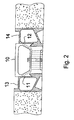
- FIG. 2 shows a double-sided version of the magnet unit according to the invention.
- This magnet unit 10 has two wedge faces 11, 12 on opposite sides, which faces attach themselves to parallel mould side units 13, 14 belonging to separate moulds.
- the mould side units are flat on the side of the cast. In this manner, several castings can be produced on a small area of the casting bed.
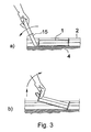
- Figure 3a is a side view of the magnet unit 1 of Fig. 1 and mould side 2 attached to casting bed 4. Detachment is carried out using tool 15 in slot 16 to lever one end of the magnet unit off the casting bed. After the initial detachment, the unit can be lifted away by hand as shown in Fig. 3b.
Landscapes
- Engineering & Computer Science (AREA)
- Manufacturing & Machinery (AREA)
- Chemical & Material Sciences (AREA)
- Ceramic Engineering (AREA)
- Mechanical Engineering (AREA)
- Forms Removed On Construction Sites Or Auxiliary Members Thereof (AREA)
- Moulds, Cores, Or Mandrels (AREA)
- Moulds For Moulding Plastics Or The Like (AREA)
- Injection Moulding Of Plastics Or The Like (AREA)
- On-Site Construction Work That Accompanies The Preparation And Application Of Concrete (AREA)
- Sewing Machines And Sewing (AREA)
Priority Applications (1)
| Application Number | Priority Date | Filing Date | Title |
|---|---|---|---|
| DK02396018T DK1232842T3 (da) | 2001-02-16 | 2002-02-13 | Magnetenhed til betonstöbeforme |
Applications Claiming Priority (2)
| Application Number | Priority Date | Filing Date | Title |
|---|---|---|---|
| FI20010076U FI4973U1 (fi) | 2001-02-16 | 2001-02-16 | Magneettiyksikkö valumuotin laitaa varten |
| FI20010076U | 2001-02-16 |
Publications (3)
| Publication Number | Publication Date |
|---|---|
| EP1232842A2 EP1232842A2 (en) | 2002-08-21 |
| EP1232842A3 EP1232842A3 (en) | 2003-09-17 |
| EP1232842B1 true EP1232842B1 (en) | 2005-07-06 |
Family
ID=8559990
Family Applications (1)
| Application Number | Title | Priority Date | Filing Date |
|---|---|---|---|
| EP02396018A Expired - Lifetime EP1232842B1 (en) | 2001-02-16 | 2002-02-13 | Magnet unit for concrete moulds |
Country Status (7)
| Country | Link |
|---|---|
| US (1) | US6742759B2 (da) |
| EP (1) | EP1232842B1 (da) |
| AT (1) | ATE299087T1 (da) |
| DE (1) | DE60204920T2 (da) |
| DK (1) | DK1232842T3 (da) |
| ES (1) | ES2243678T3 (da) |
| FI (1) | FI4973U1 (da) |
Families Citing this family (12)
| Publication number | Priority date | Publication date | Assignee | Title |
|---|---|---|---|---|
| US20050116131A1 (en) * | 2001-04-02 | 2005-06-02 | Michael Samuel | Support device |
| FI5309U1 (fi) | 2002-02-04 | 2002-04-04 | Addtek Res & Dev Oy Ab | Valumuotin laitojen kiinnitysjärjestely |
| FI5432U1 (fi) * | 2002-04-08 | 2002-07-17 | Adttek Res & Dev Oy Ab | Valumuotin irroitettava laitejärjestelmä |
| DE20309970U1 (de) * | 2003-06-27 | 2004-11-04 | Bt Baubedarf Magdeburg Gmbh | Halteeinrichtung |
| DE202005003979U1 (de) * | 2005-03-11 | 2006-07-20 | B.T. Innovation Gmbh | Schalungssystem |
| FI20050583L (fi) * | 2005-06-01 | 2006-12-02 | Elematic Oy Ab | Laitajärjestelmä valumuottiin |
| FI125406B (fi) * | 2006-01-20 | 2015-09-30 | Elematic Oyj | Muottijärjestelmä ja magneettiyksikkö |
| CA2697335C (en) * | 2006-09-15 | 2015-11-10 | Srb Construction Technologies Pty Ltd. | A magnetic clamp assembly |
| CA2697317C (en) * | 2006-09-18 | 2015-11-10 | Robert Sladojevic | A magnetic clamp |
| FI125405B (fi) * | 2008-04-29 | 2015-09-30 | Elematic Oyj | Valumuotin laitarakenne |
| FI20105685L (fi) * | 2010-06-15 | 2011-12-16 | Elematic Group Oy | Valumuotin laitayksikkö sekä laitayksikön irrotusyksikkö |
| US8876096B2 (en) * | 2012-07-05 | 2014-11-04 | The Boeing Company | Method and apparatus for forming an angled flange |
Family Cites Families (7)
| Publication number | Priority date | Publication date | Assignee | Title |
|---|---|---|---|---|
| US3530540A (en) * | 1968-03-01 | 1970-09-29 | Ralph C Mueller | Molding device |
| DE4327696C2 (de) * | 1993-08-18 | 1997-10-16 | Reymann Technik Gmbh | Schalungssystem für Betonteile |
| NO954164L (no) | 1994-11-11 | 1996-05-13 | Atle Laland | Forskalingsramme |
| DE19528842A1 (de) * | 1995-08-04 | 1997-02-06 | Reymann Technik Gmbh | Schalungssystem für Betonfertigteile |
| FI3487U1 (fi) * | 1998-03-27 | 1998-07-23 | Addtek Res & Dev Oy Ab | Valumuotin irrotettava laitajärjestelmä |
| FI4258U1 (fi) * | 1999-08-09 | 1999-12-15 | Addtek Res & Dev Oy Ab | Valumuotin irrotettava laitajärjestelmä |
| DE29920866U1 (de) * | 1999-12-01 | 2000-01-27 | Reymann Technik GmbH, 68766 Hockenheim | Schalungssystem für Betonfertigteile |
-
2001
- 2001-02-16 FI FI20010076U patent/FI4973U1/fi active
-
2002
- 2002-02-08 US US10/067,837 patent/US6742759B2/en not_active Expired - Fee Related
- 2002-02-13 DE DE60204920T patent/DE60204920T2/de not_active Expired - Lifetime
- 2002-02-13 AT AT02396018T patent/ATE299087T1/de active
- 2002-02-13 DK DK02396018T patent/DK1232842T3/da active
- 2002-02-13 ES ES02396018T patent/ES2243678T3/es not_active Expired - Lifetime
- 2002-02-13 EP EP02396018A patent/EP1232842B1/en not_active Expired - Lifetime
Also Published As
| Publication number | Publication date |
|---|---|
| US6742759B2 (en) | 2004-06-01 |
| US20020112430A1 (en) | 2002-08-22 |
| FIU20010076U0 (fi) | 2001-02-16 |
| DK1232842T3 (da) | 2005-08-01 |
| FI4973U1 (fi) | 2001-06-27 |
| DE60204920T2 (de) | 2005-12-01 |
| DE60204920D1 (de) | 2005-08-11 |
| EP1232842A3 (en) | 2003-09-17 |
| ATE299087T1 (de) | 2005-07-15 |
| ES2243678T3 (es) | 2005-12-01 |
| EP1232842A2 (en) | 2002-08-21 |
Similar Documents
| Publication | Publication Date | Title |
|---|---|---|
| EP1232842B1 (en) | Magnet unit for concrete moulds | |
| EP1075917B1 (en) | Removable side system for a concrete mould | |
| EP1778932B1 (en) | Concrete sideform system | |
| EP1900489B1 (en) | Sidewall construction of a casting mold | |
| EP0945238B1 (en) | A removal side wall system for a casting mould | |
| CN113250450B (zh) | 平衡梁 | |
| EP1810806A2 (en) | Side system for a casting mold and an attaching unit | |
| CN112609881A (zh) | 一种装配式叠合楼板 | |
| JP2001049866A (ja) | コンクリート打設用脱型型枠 | |
| US20060273235A1 (en) | Sidewall system for a casting mold | |
| KR20110044913A (ko) | 연속 주조 몰드 | |
| AU2003200265B2 (en) | Clamping arrangement for casting mold sidewalls | |
| CN219261532U (zh) | 一种叠合板中间钢筋快捷定位件 | |
| AU2020202491A1 (en) | Recess Former for Cast Plate | |
| KR20050021417A (ko) | 건축용 조립식 강재 거푸집 | |
| US7055792B2 (en) | Clamp device for side wall beams | |
| EP1380703A1 (en) | Trimmer construction for a floor built up from plate-shaped elements, and a trimmer accessory to be used therewith | |
| JP2002180548A (ja) | Pc板もしくはハーフpc板用インサート | |
| CN201560580U (zh) | 砼填充用筒体构件侧向固定架 | |
| JPH0782816A (ja) | 石材の施工方法 | |
| JP2556848Y2 (ja) | 建築用スリーブ仮固定具 | |
| JPH10298917A (ja) | 発泡体製中子およびその連結構造 | |
| CN87210460U (zh) | 节点组合模板 | |
| JPH10235629A (ja) | コンクリートブロック成形用型枠の成形面板の装着構造 | |
| AU5338500A (en) | Sideform connector means |
Legal Events
| Date | Code | Title | Description |
|---|---|---|---|
| PUAI | Public reference made under article 153(3) epc to a published international application that has entered the european phase |
Free format text: ORIGINAL CODE: 0009012 |
|
| AK | Designated contracting states |
Kind code of ref document: A2 Designated state(s): AT BE CH CY DE DK ES FI FR GB GR IE IT LI LU MC NL PT SE TR |
|
| AX | Request for extension of the european patent |
Free format text: AL;LT;LV;MK;RO;SI |
|
| PUAL | Search report despatched |
Free format text: ORIGINAL CODE: 0009013 |
|
| AK | Designated contracting states |
Kind code of ref document: A3 Designated state(s): AT BE CH CY DE DK ES FI FR GB GR IE IT LI LU MC NL PT SE TR |
|
| AX | Request for extension of the european patent |
Extension state: AL LT LV MK RO SI |
|
| 17P | Request for examination filed |
Effective date: 20040219 |
|
| RAP1 | Party data changed (applicant data changed or rights of an application transferred) |
Owner name: CONSOLIS TECHNOLOGY OY AB |
|
| AKX | Designation fees paid |
Designated state(s): AT BE CH CY DE DK ES FI FR GB GR IE IT LI LU MC NL PT SE TR |
|
| 17Q | First examination report despatched |
Effective date: 20040708 |
|
| GRAP | Despatch of communication of intention to grant a patent |
Free format text: ORIGINAL CODE: EPIDOSNIGR1 |
|
| GRAS | Grant fee paid |
Free format text: ORIGINAL CODE: EPIDOSNIGR3 |
|
| GRAA | (expected) grant |
Free format text: ORIGINAL CODE: 0009210 |
|
| AK | Designated contracting states |
Kind code of ref document: B1 Designated state(s): AT BE CH CY DE DK ES FI FR GB GR IE IT LI LU MC NL PT SE TR |
|
| PG25 | Lapsed in a contracting state [announced via postgrant information from national office to epo] |
Ref country code: LI Free format text: LAPSE BECAUSE OF FAILURE TO SUBMIT A TRANSLATION OF THE DESCRIPTION OR TO PAY THE FEE WITHIN THE PRESCRIBED TIME-LIMIT Effective date: 20050706 Ref country code: CH Free format text: LAPSE BECAUSE OF FAILURE TO SUBMIT A TRANSLATION OF THE DESCRIPTION OR TO PAY THE FEE WITHIN THE PRESCRIBED TIME-LIMIT Effective date: 20050706 |
|
| REG | Reference to a national code |
Ref country code: GB Ref legal event code: FG4D |
|
| REG | Reference to a national code |
Ref country code: CH Ref legal event code: EP |
|
| REG | Reference to a national code |
Ref country code: DK Ref legal event code: T3 |
|
| REG | Reference to a national code |
Ref country code: IE Ref legal event code: FG4D |
|
| REF | Corresponds to: |
Ref document number: 60204920 Country of ref document: DE Date of ref document: 20050811 Kind code of ref document: P |
|
| PG25 | Lapsed in a contracting state [announced via postgrant information from national office to epo] |
Ref country code: GR Free format text: LAPSE BECAUSE OF FAILURE TO SUBMIT A TRANSLATION OF THE DESCRIPTION OR TO PAY THE FEE WITHIN THE PRESCRIBED TIME-LIMIT Effective date: 20051006 |
|
| REG | Reference to a national code |
Ref country code: SE Ref legal event code: TRGR |
|
| REG | Reference to a national code |
Ref country code: ES Ref legal event code: FG2A Ref document number: 2243678 Country of ref document: ES Kind code of ref document: T3 |
|
| PG25 | Lapsed in a contracting state [announced via postgrant information from national office to epo] |
Ref country code: PT Free format text: LAPSE BECAUSE OF FAILURE TO SUBMIT A TRANSLATION OF THE DESCRIPTION OR TO PAY THE FEE WITHIN THE PRESCRIBED TIME-LIMIT Effective date: 20051212 |
|
| REG | Reference to a national code |
Ref country code: CH Ref legal event code: PL |
|
| PG25 | Lapsed in a contracting state [announced via postgrant information from national office to epo] |
Ref country code: IE Free format text: LAPSE BECAUSE OF NON-PAYMENT OF DUE FEES Effective date: 20060213 |
|
| PG25 | Lapsed in a contracting state [announced via postgrant information from national office to epo] |
Ref country code: MC Free format text: LAPSE BECAUSE OF NON-PAYMENT OF DUE FEES Effective date: 20060228 Ref country code: LU Free format text: LAPSE BECAUSE OF NON-PAYMENT OF DUE FEES Effective date: 20060228 |
|
| ET | Fr: translation filed | ||
| PLBE | No opposition filed within time limit |
Free format text: ORIGINAL CODE: 0009261 |
|
| STAA | Information on the status of an ep patent application or granted ep patent |
Free format text: STATUS: NO OPPOSITION FILED WITHIN TIME LIMIT |
|
| 26N | No opposition filed |
Effective date: 20060407 |
|
| REG | Reference to a national code |
Ref country code: IE Ref legal event code: MM4A |
|
| PG25 | Lapsed in a contracting state [announced via postgrant information from national office to epo] |
Ref country code: TR Free format text: LAPSE BECAUSE OF FAILURE TO SUBMIT A TRANSLATION OF THE DESCRIPTION OR TO PAY THE FEE WITHIN THE PRESCRIBED TIME-LIMIT Effective date: 20050706 |
|
| PG25 | Lapsed in a contracting state [announced via postgrant information from national office to epo] |
Ref country code: CY Free format text: LAPSE BECAUSE OF FAILURE TO SUBMIT A TRANSLATION OF THE DESCRIPTION OR TO PAY THE FEE WITHIN THE PRESCRIBED TIME-LIMIT Effective date: 20050706 |
|
| REG | Reference to a national code |
Ref country code: FR Ref legal event code: TP Owner name: ELEMATIC GROUP OY AB, FI Effective date: 20111121 |
|
| REG | Reference to a national code |
Ref country code: GB Ref legal event code: 732E Free format text: REGISTERED BETWEEN 20120712 AND 20120718 |
|
| PGFP | Annual fee paid to national office [announced via postgrant information from national office to epo] |
Ref country code: FI Payment date: 20140212 Year of fee payment: 13 Ref country code: NL Payment date: 20140218 Year of fee payment: 13 Ref country code: SE Payment date: 20140218 Year of fee payment: 13 Ref country code: DE Payment date: 20140219 Year of fee payment: 13 Ref country code: DK Payment date: 20140218 Year of fee payment: 13 |
|
| PGFP | Annual fee paid to national office [announced via postgrant information from national office to epo] |
Ref country code: ES Payment date: 20140219 Year of fee payment: 13 Ref country code: FR Payment date: 20140219 Year of fee payment: 13 Ref country code: AT Payment date: 20140212 Year of fee payment: 13 Ref country code: IT Payment date: 20140225 Year of fee payment: 13 Ref country code: BE Payment date: 20140218 Year of fee payment: 13 |
|
| PGFP | Annual fee paid to national office [announced via postgrant information from national office to epo] |
Ref country code: GB Payment date: 20140218 Year of fee payment: 13 |
|
| PG25 | Lapsed in a contracting state [announced via postgrant information from national office to epo] |
Ref country code: BE Free format text: LAPSE BECAUSE OF NON-PAYMENT OF DUE FEES Effective date: 20150228 |
|
| REG | Reference to a national code |
Ref country code: DE Ref legal event code: R119 Ref document number: 60204920 Country of ref document: DE |
|
| REG | Reference to a national code |
Ref country code: NL Ref legal event code: V1 Effective date: 20150901 |
|
| REG | Reference to a national code |
Ref country code: DK Ref legal event code: EBP Effective date: 20150228 |
|
| REG | Reference to a national code |
Ref country code: SE Ref legal event code: EUG |
|
| PG25 | Lapsed in a contracting state [announced via postgrant information from national office to epo] |
Ref country code: NL Free format text: LAPSE BECAUSE OF NON-PAYMENT OF DUE FEES Effective date: 20150901 |
|
| REG | Reference to a national code |
Ref country code: AT Ref legal event code: MM01 Ref document number: 299087 Country of ref document: AT Kind code of ref document: T Effective date: 20150213 |
|
| GBPC | Gb: european patent ceased through non-payment of renewal fee |
Effective date: 20150213 |
|
| PG25 | Lapsed in a contracting state [announced via postgrant information from national office to epo] |
Ref country code: FI Free format text: LAPSE BECAUSE OF NON-PAYMENT OF DUE FEES Effective date: 20150213 |
|
| REG | Reference to a national code |
Ref country code: FR Ref legal event code: ST Effective date: 20151030 |
|
| PG25 | Lapsed in a contracting state [announced via postgrant information from national office to epo] |
Ref country code: SE Free format text: LAPSE BECAUSE OF NON-PAYMENT OF DUE FEES Effective date: 20150214 Ref country code: AT Free format text: LAPSE BECAUSE OF NON-PAYMENT OF DUE FEES Effective date: 20150213 |
|
| PG25 | Lapsed in a contracting state [announced via postgrant information from national office to epo] |
Ref country code: IT Free format text: LAPSE BECAUSE OF NON-PAYMENT OF DUE FEES Effective date: 20150213 |
|
| PG25 | Lapsed in a contracting state [announced via postgrant information from national office to epo] |
Ref country code: GB Free format text: LAPSE BECAUSE OF NON-PAYMENT OF DUE FEES Effective date: 20150213 Ref country code: DK Free format text: LAPSE BECAUSE OF NON-PAYMENT OF DUE FEES Effective date: 20150228 Ref country code: DE Free format text: LAPSE BECAUSE OF NON-PAYMENT OF DUE FEES Effective date: 20150901 |
|
| PG25 | Lapsed in a contracting state [announced via postgrant information from national office to epo] |
Ref country code: FR Free format text: LAPSE BECAUSE OF NON-PAYMENT OF DUE FEES Effective date: 20150302 |
|
| REG | Reference to a national code |
Ref country code: ES Ref legal event code: FD2A Effective date: 20160329 |
|
| PG25 | Lapsed in a contracting state [announced via postgrant information from national office to epo] |
Ref country code: ES Free format text: LAPSE BECAUSE OF NON-PAYMENT OF DUE FEES Effective date: 20150214 |